 Viktor Gribniak1,2*
 Arvydas Rimkus1,2,3Linas Plioplys1,2,3Ieva Misiūnaitė1,2Mantas Garnevičius1,2,3Renata Boris3Antanas Šapalas2
- 1Laboratory of Innovative Building Structures, Vilnius Gediminas Technical University (Vilnius Tech), Vilnius, Lithuania
- 2Department of Steel and Composite Structures, Vilnius Tech, Vilnius, Lithuania
- 3Institute of Building Materials, Vilnius Tech, Vilnius, Lithuania
This study focuses on the flexural behavior of pultruded glass fiber-reinforced polymer (GFRP) profiles developed for structural applications. Fiber content is a commonly accepted measure for estimating the resistance of such components, and technical datasheets describe this essential parameter. However, its direct implementation to the numerical simulations can face substantial problems because of the limitations of standard test protocols. Furthermore, the fiber mass percentage understandable for producers is unsuitable for typical software considered the volumetric reinforcement content. This manuscript exemplifies the above situation both experimentally and analytically, investigating two GFRP square hollow section (SHS) profiles available at the market. A three-point bending test determines the mechanical performance of the profiles in this experimental program; a digital image correlation system captures deformations and failure mechanisms of the SHS specimens; a standard tensile test defines the material properties. A simplified finite element (FE) model is developed based on the smeared reinforcement concept to predict the stiffness and load-bearing capacity of the profiles. An efficient balance between the prediction accuracy and computation time characterizes the developed FE approach that does not require specific descriptions of reinforcement geometry and refined meshes necessary for modeling the discrete fibers. The proposed FE approach is also used to analyze the fiber efficiency in reinforcing the polymer matrix. The efficiency is understood as the model’s ability to resist mechanical load proportional to the dry filaments’ content and experimental elastic modulus value. Scanning electron microscopy relates the composite microstructure and the mechanical performance of the selected profiles in this study.
Introduction
The development of novel material-oriented design concepts aligns with the current industrial trends (Gribniak, 2020). The essential physical characteristics of fiber-reinforced polymers (FRP), such as lightweight, electromagnetic transparency, and excellent corrosion and fatigue resistance, make these materials a promising alternative to steel (Ye et al., 2020; Wang et al., 2021). Continuous glass filaments are typical reinforcement for structural applications composing GFRP (glass-fiber-reinforced polymer) pultruded components (Gribniak et al., 2019; Tu et al., 2019; Zhang et al., 2020). The well-developed pultrusion technologies allow distributing continuous mechanically resistant filaments in a polymer matrix that protects the reinforcement from the unfavorable environment. The pultrusion is possible in a large volume at low operating costs, high production rate, high fiber content, product reproducibility, and dimensional tolerances (Correia, 2013).
The filament distribution controls the mechanical properties of pultruded components (Grund et al., 2019). The structural load and pultrusion directions are often different; the profiles must also resist the bolt removal-induced pulling stresses. Therefore, a combination of the smooth unidirectional roving and mats allocating fibers in the transverse direction composes the composite reinforcement architecture (Fiberline, 2003; Correia, 2013). However, technical datasheets typically characterize only the mechanical properties of the fibers distributed in the pultrusion direction. Thus, direct implementation of this information to the numerical simulations can face substantial problems because of the limitations of standard test protocols (Gribniak et al., 2017, 2019, 2021). Furthermore, the fiber mass percentage acceptable for producers is unsuitable for finite element (FE) software considered the volumetric reinforcement content (Gribniak et al., 2012, 2019).
This manuscript exemplifies the above situation both experimentally and analytically, investigating two GFRP square hollow section (SHS) profiles available at the market. Various structural applications employ such elements because of their aesthetic appearance and high resistance to torsion (Wu and Bai, 2014; Misiunaite et al., 2020). A three-point bending test determines the mechanical performance of the profiles in this test program; a digital image correlation (DIC) system captures deformations and failure mechanisms of the SHS specimens.
Numerical simulations reported in the literature focus on two general purposes (Figure 1A):
1) Verification of constitutive models, using test results of laboratory specimens (Li et al., 2015; Thorhallsson et al., 2017; Siwowski et al., 2018; Chen et al., 2019; Eskandari et al., 2019; Xing et al., 2019; Zhang et al., 2019a, 2019b).
2) Analysis of full-scale structural elements (He et al., 2012; Votsis et al., 2017; Mahboubi and Shiravand, 2019; Muc et al., 2020; Yang et al., 2020).
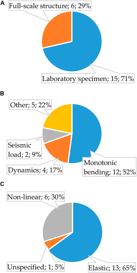
FIGURE 1. Structure of the literature publications related to numerical modeling: (A) Distribution by the modeling object; (B) Loading situation; (C) Specified material parameters. Note: the indicated cases’ number can exceed the articles’ number because of the research object overlapping.
Figure 1 schematically describes the distribution structure of the selected articles (Keller and Schollmayer, 2004; He et al., 2012; Li et al., 2015; Robinson and Melby, 2015; Cai et al., 2017; Thorhallsson et al., 2017; Votsis et al., 2017; Mandal and Chakrabarti, 2018; Siwowski et al., 2018, 2019; Chen et al., 2019; Eskandari et al., 2019; Mahboubi and Shiravand, 2019; Papapetrou et al., 2019; Xing et al., 2019; Yuan et al., 2019; Zhang et al., 2019a, 2019b; Muc et al., 2020; Yang et al., 2020) regarding the simulation object, loading situation, and modeling parameters. The literature analysis identified the following simulation targets (aspects): failure of FRP composites (Eskandari et al., 2019), debonding (Cai et al., 2017; Muc et al., 2020), and the structural components elastic simplifications (Keller and Schollmayer, 2004; He et al., 2012; Votsis et al., 2017; Mandal and Chakrabarti, 2018; Yuan et al., 2019; Yang et al., 2020). The first two aspects are typical for the analysis of the laboratory samples (Cai et al., 2017; Eskandari et al., 2019; Muc et al., 2020)—a bending specimen is the typical research object (Figure 1B). In some cases, shear failure (Eskandari et al., 2019; Xing et al., 2019), the composite components’ bond behavior and inter-laminar slippage are among the modeling parameters (Robinson and Melby, 2015; Cai et al., 2017; Chen et al., 2019; Eskandari et al., 2019; Muc et al., 2020). Figure 1C shows that elastic constitutive (or elastic-plastic) models are typical for numerical analysis and do not focus on full-scale structures (He et al., 2012; Votsis et al., 2017; Mahboubi and Shiravand, 2019; Yang et al., 2020).
The advanced simulations attempt to represent the physical heterogeneity intrinsic to FRP composites. The difference in the elastic moduli specified in different directions often simulates the material anisotropy (He et al., 2012; Robinson and Melby, 2015; Chen et al., 2019; Eskandari et al., 2019; Papapetrou et al., 2019; Muc et al., 2020). The typical numerical models assume FRP material structure homogeneous, making no distinction between the polymer and filament materials. Laboratory tests (He et al., 2012; Siwowski et al., 2019; Muc et al., 2020) and manufacturers’ certificates (Votsis et al., 2017; Yang et al., 2020) define the material properties of the FRP composite. Thus, the anisotropic material characteristics become depending on empirical relationships and test conditions (Tu et al., 2019).
On the contrary, this study employs the smeared reinforcement model, assuming the 1D virtual filaments uniformly spread inside the solid polymer body. The fibers have no specific geometry—the volume percentage and orientation angle describe the mechanical reinforcement properties. On the one hand, that ensures the separation of the glass filaments’ and polymer matrix’s material models, including the failure criteria. On the other hand, such a simplification allows developing the FE model not requiring refined meshes necessary for modeling the discrete fibers, making it suitable for engineering applications. Besides, the proposed model estimates the fiber reinforcement efficiency. That is understood as the model’s ability to predict the actual mechanical resistance (flexural stiffness) under the assumption of experimental elastic moduli of the GFRP constituents, i.e., the polymeric matrix and bare fibers. The scanning electron microscopy (SEM) analysis within the current testing program framework relates the internal structure and mechanical performance of the GFRP composite profiles.
Test Program
As mentioned in the introduction, this manuscript explores two GFRP square hollow section (SHS) profiles available at the market. The reputable in Europe SHS pultruded profiles produced by Fiberline (Denmark) represent the reference object. This profile has a 50 × 50 × 5 mm (height × width × thickness) cross-section. Locally produced GFRP 40 × 40 × 3.2 mm profile (Ugira Ltd., Lithuania) represents the alternative. Polyester and vinylester resins reinforced with continuous E-glass filaments respectively compose Fiberline and Ugira profiles; the manufacturers’ provided fiber mass percentages were 60 ± 5% (Fiberline) and 75% (Ugira). In addition, the latter manufacturer specifies the nominal mechanical characteristics of the GFRP constituents. Table 1 presents the corresponding material parameters. Remarkably, Fiberline describes only approximate fiber content, focusing on the mechanical behavior of the GFRP composite. Thus, the general information provided by El-Wazery et al. (2017) describes the missed parameters of the Fiberline composite constituents necessary for the FE modeling.
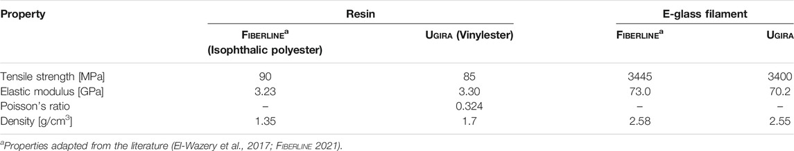
TABLE 1. Material properties of the GFRP composite constituents.
Fiber Content Analysis
The first experimental research stage focuses on fiber quantification in the GFRP composites. The standard ISO 1172:1996 “Textile-glass-reinforced plastics—Prepregs, molding compounds and laminates—Determination of the textile-glass and mineral-filler content—Calcination methods” defines the test procedure requirements. An electric furnace Snol 7.2/1100 (Snol, Lithuania) was used for the heating tests. For that purpose, small fragments (≈10 g), cut from the webs and corners of the profiles (Figure 2), were dried until the constant weight at 105 ± 5°C (the drying time = 24 h). After that, the specimens were heated at 625 ± 5°C until the polymer evaporated. The heating regime: 2 h to reach a temperature of 625°C and 3 h to achieve a constant weight. The heating procedure determines the mass percentage of fibers wf, and the following equation defines the volume fraction Vf:
where ρf and ρm are the fiber and matrix densities (Table 1). The above parameter is necessary for the numerical modeling to describe the fiber reinforcement area in the cross-section (Gribniak et al., 2012, 2021). However, this testing methodology gets only an approximate estimate of wf because of neglecting the heat-resistant aggregates’ effect (Bazli and Abolfazli, 2020).
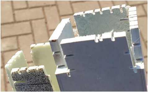
FIGURE 2. The GFRP profiles after cutting the samples for the heating tests.
Figure 3 shows the analysis results of three (#1–#3) web and corner samples for each profile type. This figure demonstrates that the estimated fiber content (71.0%) exceeds the mass fraction declared by Fiberline (60 ± 5%). The neglecting of the weight of the heat-resistant aggregates cannot explain such a big difference that can be a consequence of the complex reinforcement architecture if the manufacturer specifies only longitudinal fiber content. Fiberline (2003) states that various types of roving and intricate weaves and mats compose the reinforcement system of the pultruded structural profiles. Unfortunately, the detailed information about the fiber percentage and orientation is missed in the Fiberline datasheets.
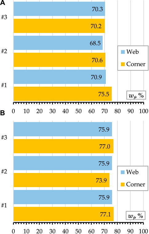
FIGURE 3. Estimated mass fiber fraction in GFRP composite: (A) Fiberline profile; (B) Ugira sample.
On the contrary, the average Ugira fiber fraction (75.9%) agrees with the declared value (75%), indirectly indicating the simplicity of the reinforcement layout. Eq. 1 results in the average volume fraction of 56.2 and 67.8% for Fiberline and Ugira profiles. The calculations employ density values specified in Table 1.
Figure 3 also demonstrates almost identical fiber content in the web and corner specimens for both profiles. It means that the current pultrusion technologies solved the resin localization problems at the web-flange junction identified previously (Feo et al., 2013).
Mechanical Properties of GFRP Composite
The tensile coupon tests were carried out for Ugira profiles within the framework of this experimental program by following the ASTM D 3039/D 3039M-17 “Standard Test Method for Tensile Properties of Polymer Matrix Composite Materials” requirements. The mechanical properties, i.e., the tensile strength and elastic modulus, were determined in the pultrusion direction, corresponding to the filament orientation. All coupons were tested using a 250 kN capacity servo-hydraulic machine Z250 (Zwick, Germany). Four coupons were tested for Ugira profiles. Table 2 summarizes the tensile test results. This table also includes the tensile test outcomes provided by Fiberline (2021).
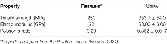
TABLE 2. Material properties of the GFRP composites.
The tensile coupon tests for the Fiberline profiles were not carried out in this illustrative study. Thus, this manuscript provides a general view of the problems related to developing a reliable numerical model regarding the incomplete information provided in the producers’ certificates.
Microstructure Analysis
The microstructure analysis is a part of the current experimental study. The filaments after the heating tests (see section “Fiber Content Analysis” above) and the web and corner microsection specimens of the SHS profiles (Figure 2) define the investigation objects. A field emission scanning electron microscope JSM-7600F (Jeol, Japan) was used for the microstructure analysis. The scanning electron microscopy (SEM) parameters were as follows: 10 kV voltage, 11–13 mm distance to the specimen surface and magnification varied from ×50 to ×1200.
Figure 4 shows the SEM images of separate fibers obtained during the heating tests. The difference in fiber diameter is the center outcome of these images—the Fiberline samples vary in the 16–22 μm range; the alternative fibers’ diameter varies from 32 to 38 μm.
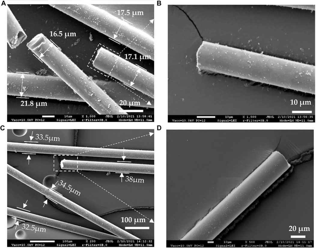
FIGURE 4. SEM images of separate fibers: (A,B) Fiberline profile; (C,D) Ugira sample. Note: the rectangles localize the zoomed view place of the images (B,D).
Abrasive grinding and thin Au layer electrically conductive covering in a vacuum with a Quorum Q150R ES equipment (Quorum, United Kingdom) prepared the microsection specimens. Figures 5, 6 show the SEM images of the web and corner specimens’ surfaces normal to the pultrusion direction. The Fiberline samples demonstrate a more dense structure than the Ugira specimens do. Independently of the sampling (Figures 5A,B, 6A,B), the fiber and matrix contact zones have no visible defects. On the contrary, deficiencies and voids of size varying from 10 to 33 μm are characteristic of the Ugira samples (Figures 5C,D, 6C,D).
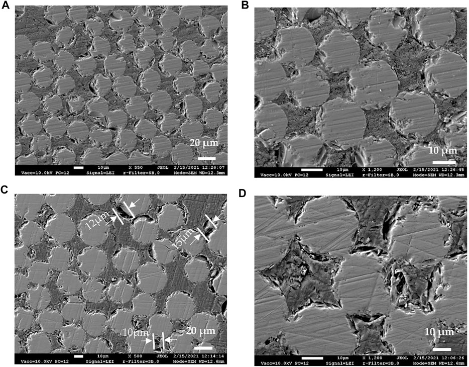
FIGURE 5. SEM images of the web zones: (A,B) Fiberline profile; (C,D) Ugira sample.
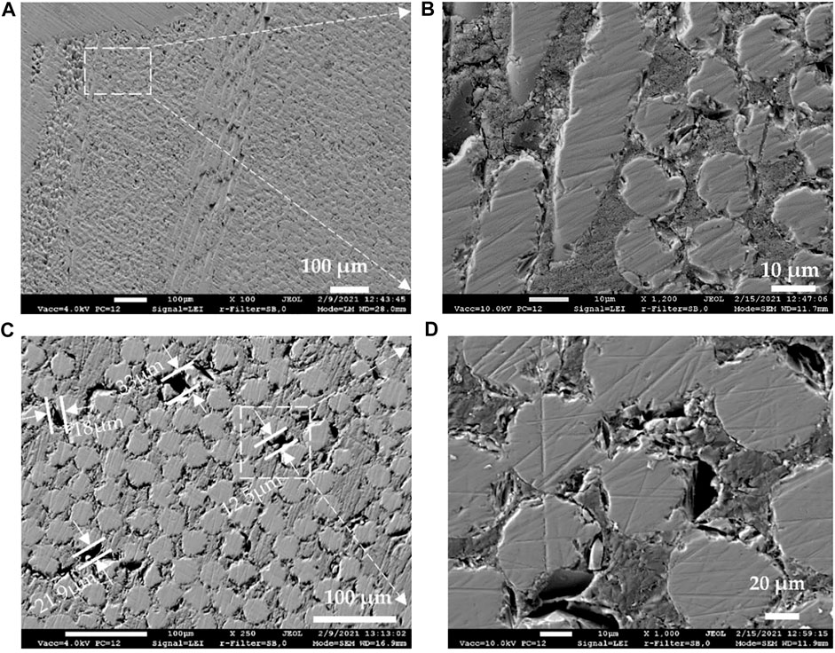
FIGURE 6. SEM images of the corner zones: (A,B) Fiberline profile; (C,D) Ugira sample. Note: the rectangles localize the zoomed view place of the images (B,D).
Flexural Tests
The material heterogeneity and anisotropy of GFRP composites alter material performance within the pultruded cross-section (Correia, 2013). Besides, a complex stress-strain behavior contributes to the tensile and compressive material properties distinction in a flexural sample (Insausti et al., 2020). Thus, three-point bending tests were included in this experimental program, determining the mechanical properties of structural profiles. This study employs three Fiberline (50 × 50 × 5 mm) and five Ugira (40 × 40 × 3.2 mm) SHS profile samples. All the test samples had a length of 1000 mm and were tested until failure. Steel rollers and bearing steel plates protected the GFRP profile from the local damage. Figure 7 shows the loading setup.
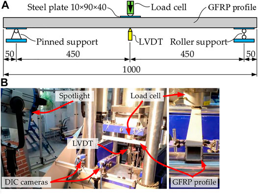
FIGURE 7. Three-point bending test: (A) Loading scheme; (B) Test setup.
A 5 MN capacity servo-hydraulic machine LFV 5000 (w+b, Switzerland) loaded the profiles under the displacement control, measuring the applied load with a 100 kN capacity load cell. A digital image correlation (DIC) system captured surface deformation of the profiles; paired 100 mm range and 0.01 mm precision linear variable displacement transducers (LVDT) measured the mid-span vertical displacements. An Almemo 2890-9 data logger acquired the test data every second.
Figure 8 shows the average mid-span displacements measured by the paired LVDTs (Figure 7A). The load-displacement diagrams of all specimens (i.e., SFl1-SFl3 and SUg1-SUg5) are almost linear until the ultimate load. The samples also revealed similar flexural stiffness and failure mechanism—crushing of the compressive zone followed by cross-section integrity loss. Figure 9 shows the typical failure cases.
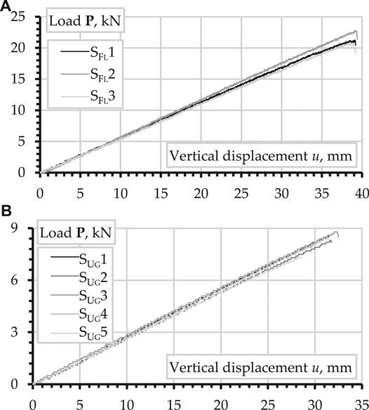
FIGURE 8. Three-point bending test results: (A) Fiberline profiles; (B) Ugira samples.
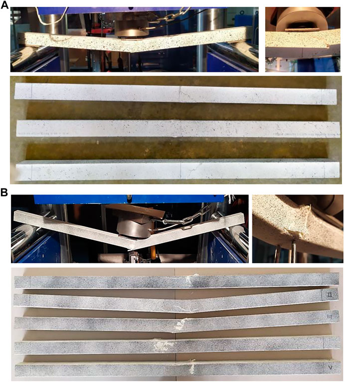
FIGURE 9. Failure mechanisms: (A) Fiberline profiles; (B) Ugira samples.
The DIC system (Figure 7B) captures the relative displacements of the surface points (pixels) recognized at the monitoring surface at the rate of one image per 500 N with the aid of the Davis 8.1.6 software by Lavision. That allows tracking relative movements of any pixels chosen at the image processing stage (Misiunaite et al., 2020).
Numerical Modeling
This section introduces the simplified finite element (FE) modeling approach to the engineering analysis of GFRP pultruded components. The modeling intends to ensure acceptable adequacy with the maximal allowable mesh size. This principle complies with the current structural modeling trends (Rimkus et al., 2020) when the finite element numbers’ limitation determines the model optimization objective. Furthermore, the proposed modeling concept allows estimating the fiber reinforcement efficiency that is understood as the profile ability to resist mechanical load proportional to the dry filaments’ content and experimental elastic moduli of the GFRP constituents.
Finite Element Model
The FE model employs the smeared reinforcement concept using commercial FE software Atena (Cervenka, 2002). Figure 10 sketches the FE modeling concept following that virtual filaments are uniformly distributed inside solid finite elements. The straight fibers have no specific geometry—the volume percentage and orientation (regarding global coordinate system) describe the mechanical properties of the reinforcement having a perfect contact to the matrix (i.e., no slip between the filament and finite elements is allowed). The fibers are not resistant to axial compression. The solid finite elements can include several reinforcement systems (layers) smeared in different directions to represent a complex filaments architecture characteristic of particular FRP pultruded components.
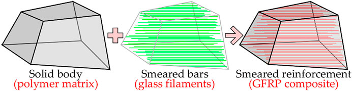
FIGURE 10. Adapting the smeared reinforcement concept (Cervenka, 2002).
In this study, the 3D solid finite elements describe the polymer matrix, assuming the fracture mechanic principles for the tensile failure and the plasticity approach to the compressive failure. Figure 11 shows the softening law in compression described with a linear descending branch of the diagram. In this figure, fc is the compressive strength; fc0 is the onset of non-linear compressive behavior; εcp is the plastic strain at the compressive strength; εd is the compressive ductility. The ratio between the plastic displacement and crack band size defines the strain εd. The crack band determines a fictitious crushing zone that is related to the finite element size. The principal compressive stresses describe the failure plane normal to the stress direction; the post-peak compressive strain localizes in this plane. Such formulation reduces the FE mesh dependency of the model (Cervenka, 2002).
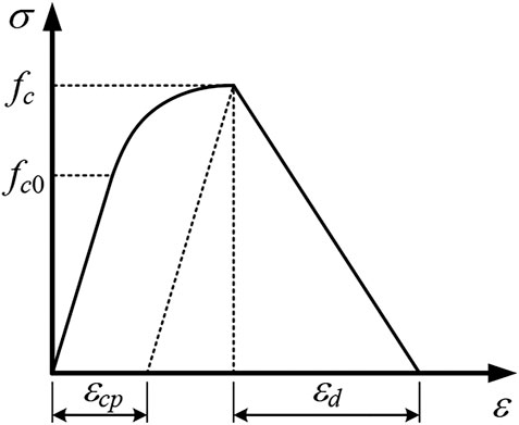
FIGURE 11. Constitutive model of polymer matrix in compression.
A layer of the smeared reinforcement models the glass filaments. In such a way, a separate 1D material model, coinciding with the pultrusion direction, describes the reinforcement. A perfectly elastic-brittle constitutive law defines the tension failure of the fibers, which do not resist the compression stresses.
Figure 12 shows the numerical model built using 3D isoparametric brick eight-node finite elements with eight integration points and an average 3 mm size. The modeled steel plates protect the GFRP profile from stress concentration at the supports and load application point. These boundary and loading conditions (Figure 12A) correspond to the physical tests (Figure 7A). The FE model of the Ugira profile (Figure 12B) reflects the shape imperfection (i.e., a relative rotation of the inner rectangular shape in the cross-section, Figure 12C) that resulted from the manufacturing flaw. Several FE simulations were carried out, varying only the assumed fiber content Vf. Table 3 summarizes assumed parameters of the numerical models. The following section describes the Vf quantification principles.
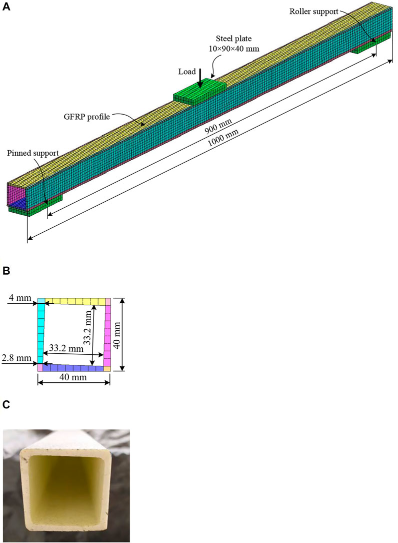
FIGURE 12. Flexural Ugira profile: (A) FE model; (B) The modeled cross-section; (C) Actual cross-section imperfection.
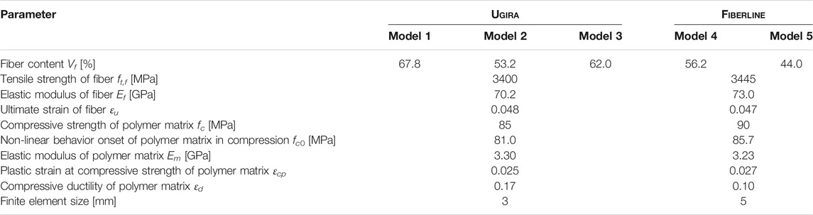
TABLE 3. Parameters of the numerical models.
Fiber Efficiency Analysis
Tables 1, 2 provide experimental values of all material parameters necessary for the numerical modeling of the Ugira profile. Therefore, simulations of this profile illustrate the proposed fiber efficiency concept and the limitations of the standard testing procedures. The material parameters listed in Table 1 describe the elastic constitutive models of the vinylester resin and smeared reinforcement in all simulations. The equal compressive and tensile strength values were assumed for the polymer.
Model 1 accepts the volume percentage Vf = 67.8%, corresponding to the fraction experimentally determined in the “Fiber Content Analysis” section above. The tensile coupon test (section “Mechanical Properties of GFRP Composite” above) defines the fiber content of Model 2—the external tensile load P induces two internal forces acting on the polymer matrix Nm and glass fibers Nf:
The average axial strains can express the above force components as follows
where E, A, and ε are the elastic modulus, area, and average axial strain; the indexes c, m, and f correspond to the GFRP composite, polymer matrix, and glass filaments. Note, the volume content is the center parameter describing the reinforcement area Af; the fiber mass percentage is not suitable for this purpose.
The Navier-Bernoulli hypothesis (planar strain distribution within a cross-section height) postulates equality of the average strains:
simplifying Eq. 3. Thus, the following formula expresses the relationship between the volumetric fiber fraction Vf and the areas A presented in Eq. 3:
The solution of Eq. 3, assuming the simplifications of Eqs 4, 5 and the experimental value of the composite coupon elastic modulus Ec,exp, determines the efficient reinforcement fraction Vf,eff as follows
Tables 1, 2 describe the elastic moduli for determining the efficient volume Vf,eff = 53.2% assumed in Model 2. This calculated fraction is well below the experimentally determined value of 67.8% (taken in Model 1).
The vertical displacement, applied in small increments (0.3 mm), determined the load-bearing capacity of the models. The deformation problem was solved in a 3D formulation by the Newton-Raphson iteration procedure. Figure 13 demonstrates the inadequacy of the volume fraction Vf,eff determined from the tensile coupon test results to predict the deformation behavior of the GFRP profile (Model 2). Besides, the fiber fraction was tailored to represent adequately the experimental diagrams shown in Figure 8B. The iterative trial-and-error process resulted in the content Vf,eff = 62.0% assumed in Model 3; Figure 13 demonstrates the deformation prediction adequacy.
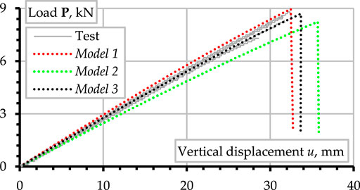
FIGURE 13. Comparison of measured and numerically predicted load-vertical displacement diagrams at the Ugira profile mid-span.
Verifying Model 3
Misiunaite et al. (2020) described the verification procedure principles. This manuscript compares the local deformations predicted by Model 3 and the DIC surface monitoring results. The DIC system (Figure 7B) estimates local strains near the steel plate edge, using the 10 mm virtual strain gauges, as Figure 14A shows. Model 3 determines the relative displacements of the nodes corresponding to the virtual gauge positions (Figure 14B).
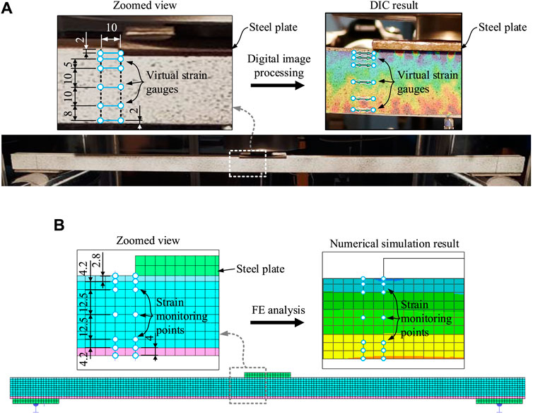
FIGURE 14. Local strains of Ugira profile: (A) Digital image correlation system; (B) Finite element analysis.
Figure 15A shows the strain distribution over the profile height identified by the DIC system capable of capturing relative pixel displacements belonging to the vertical monitoring surface (colored areas in Figure 15). Thus, the DIC diagrams (Figure 15A) do not reach the profile horizontal surfaces. The rounded corners of the SHS profile (Figure 12C) define the unidentified areas. The FE model did not represent the corners’ roundness (Figure 12B). That is a consequence of the engineering simplifications, determining the FE modeling principles. Therefore, the simulated diagrams (Figure 15B) have no limitations characteristic of the DIC system. The strain profiles are related to the corresponding external load P.
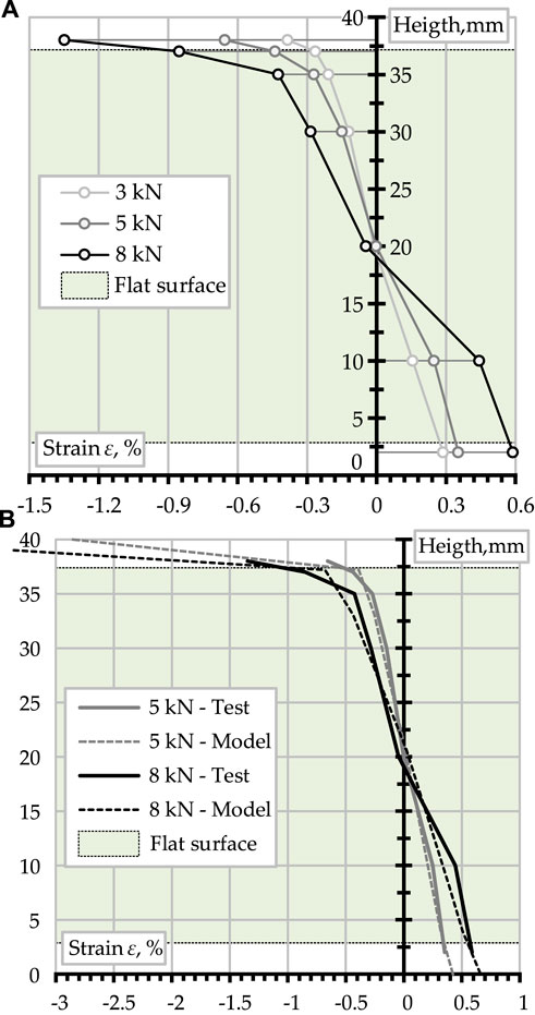
FIGURE 15. Local strain distribution along Ugira profile height: (A) Digital image correlation (DIC) results; (B) Comparison of the DIC and FE modeling results (predictions by Model 3).
The DIC and numerical simulation results’ comparison (Figure 15B) proves the above inference—Model 3 correctly represents the compressive strain increase while the smeared reinforcement does not resist compression (Cervenka, 2002). The comparative analysis of these diagrams proves sufficient adequacy of Model 3 predicting non-linear deformation behavior of the GFRP composite profile. In most cases, the differences between the tensile strains calculated using FE and estimated by the DIC system do not exceed 10%. The average strain differences do not exceed 15%, with the maximum errors located near the neutral axes (where the strain magnitudes are comparable with the measurement tolerance). Failure of the compressive zone governs the predicted ultimate load (Figure 13). That agrees with the results shown in Figure 9 and the literature findings (Correia et al., 2011; Wu and Bai, 2014; Wu et al., 2019; Alaedini et al., 2021; Almeida-Fernandes et al., 2021).
The engineering application defines the optimum FE mesh requirement—a sufficiently coarse mesh must ensure acceptable prediction accuracy. Using the 1.5 and 1.0 mm average FE size, two additional simulations verified the Model 3 prediction adequacy. (This manuscript focusing on the physical investigation aspects does not present those simulation results.) The mesh sensitivity analysis revealed the following outcomes.
1) The mesh size does not affect the flexural stiffness prediction results. That is the expected consequence of the smeared reinforcement model’s robustness for engineering application (Cervenka, 2002; Gribniak et al., 2010).
2) The mesh size-reduction reduces the predicted resistance of the SHS profile. For instance, Model 3, assuming a 3 mm FE size, overestimates the load-bearing capacity of the experimental profiles by 4.7% (Figure 13); the models having 1.5 and 1.0 mm mesh size underestimates the ultimate load by 8.2 and 17.3%, respectively. Besides, the mesh refinement causes almost 24 times and more than 42 times the calculation time regarding Model 3, making the fine FE meshes unacceptable in practice.
Analysis of the Fiberline Profile
The absence of materials parameters (Table 1) essential for the proposed FE approach makes the Fiberline profile analysis only illustrative. Numerical simulations of the bending profile employed the same procedure as specified in the “Finite Element Model” section; the “Flexural Tests” section describes the modeling object. Figure 16 shows the corresponding numerical model built using 3D isoparametric brick eight-node finite elements with eight integration points and an average size of 5 mm. The modeled steel plates preserve the GFRP SHS profile from stress concentration at the supports and load application point. Figure 16A defines the boundary and loading conditions, representing the physical tests (Figure 7A). Figures 16B,C show that the Fiberline model has no geometry imperfections characteristic of the Ugira profile (Figure 12B). However, both FE models ignore the corner roundness of the SHS profiles (Figures 12B, 16B) because of the engineering simplification.
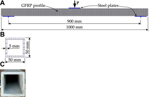
FIGURE 16. Flexural Fiberline profile: (A) FE model; (B) The modeled cross-section; (C) Cross-section.
In the same manner, as described in the “Finite Element Model” section, the 3D solid finite elements describe the polymer matrix; smeared reinforcement represents the glass filaments (Figure 10). The respective constitutive model of the GFRP material employs the polyester resin and E-glass fiber properties obtained from the literature (El-Wazery et al., 2017; Fiberline, 2021) and presented in Table 1.
Two FE simulations were carried out, assuming different fiber volume fractions. Model 4 considers a profile with the 56.2% filament content estimated from the mass fraction obtained in the “Fiber Content Analysis” section. Model 5 assumes the fiber volume fraction of 44.0% that corresponds to the manufacturer specified nominal mass fraction (60%) transformed by Eq. 1 and the constituent material densities ρm and ρf defined by Fiberline (2021).
Figure 17 compares the numerical prediction and the experimentally measured vertical displacements at the mid-span. The FE simulations consider the load increments applied in small (0.4 mm) steps. Model 4 demonstrates the inadequacy of the filament content estimated using the mass fraction values obtained during the heating tests (the “Fiber Content Analysis” section). Still, Model 5 demonstrates good agreement with experimental observations.
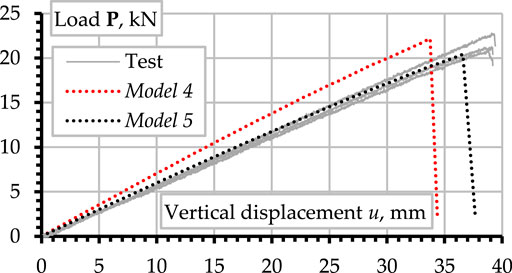
FIGURE 17. Comparison of measured and numerically predicted load-vertical displacement diagrams at the Fiberline profile mid-span.
Discussion of the Results
Limitations of the Standard Coupon Test
The standard tests consider material fragments. That is acceptable for homogenous media such as metals and pure polymers. However, the fiber reinforcement makes the coupons cut from FRP composites unrepresentative for investigating material properties. Figure 18 shows a microstructure corresponding to the tension coupon cut-side surface consistent with the pultrusion direction of the Ugira profile (the “Mechanical Properties of GFRP Composite” section). Numerous damaged filaments result from such a cut. This figure also demonstrates the bond damages of the separate fibers (Figure 18B). Similar surfaces define the boundaries of the coupon samples for determining the effective fiber fraction Vf,eff in Model 2 (the “Fiber Efficiency Analysis” section). The filament damages (Figure 18A) explain the reinforcing efficiency losses (compare Vf,eff of Model 2 and Model 3).
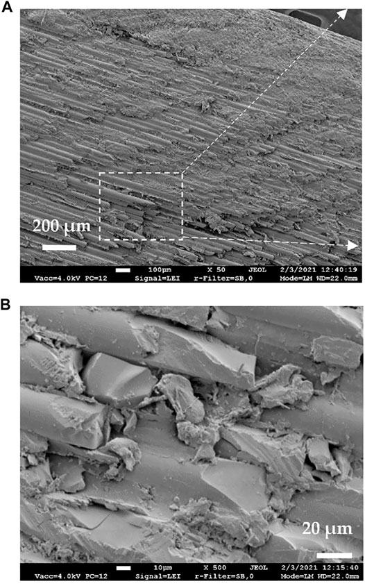
FIGURE 18. A microstructure corresponding to the tension coupon cut-side surface consistent with the pultrusion direction: (A) ×50 and (B) ×500 magnifications. Note: the rectangle localizes the zoomed view place of the image (B).
The numerical analysis (the “Analysis of the Fiberline Profile” section) of the Fiberline composite elastic modulus (Table 2) highlights a remarkable underestimation of the fiber reinforcement efficiency based on the tension coupon tests (Fiberline, 2021). Under the assumption of the elastic moduli of the composite and constituents from Tables 1, 2, Eq. 6 defines Vf,eff = 26.9% that is well below the fiber fraction 44.0% assumed in Model-5 (Figure 17). That indicates the inapplicability of the standard coupon tests for constitutive modeling of FRP composites. Furthermore, the material properties estimation error increases with the decrease of the sample size, i.e., with the cut-side area increase regarding the sample cross-section dimensions.
This study also questions the clarity of the manufacturer datasheets. The complex internal architecture of the Fiberline composite is a possible explanation of the inconsistency between the declared (≈60%) and assessed in the “Fiber Content Analysis” section (71.0%) fiber contents. Figures 6A,B illustrate the differences in the filament orientation regarding the pultrusion direction, but the producer does not provide any detailed information on the filament fraction quantification. The FRP constituencies (fibers and polymer) characterization results can help identifying the effective fiber fraction Vf,eff essential for the numerical simulations.
Numerical Model Reliability
Table 4 describes the numerical predictions’ accuracy described in the flexural stiffness EI and ultimate load Pu terms. The first three models represent the Ugira profile, and the Fiberline SHS sample was the modeling object of the remaining two simulations. The identical profile models had the same geometry, FE mesh, and material parameters; the volumetric fiber content was only the difference. The elastic analysis defines the flexural stiffness as follows
where P and u define the load and corresponding vertical displacement; l is the loading span (= 0.9 m, Figures 7A, 16A). The elastic behavior of the flexural profiles (Figure 8) makes the above simplification possible. The stiffness EI was calculated for the experimentally determined P-u pairs at all ascending load stages. Table 4 shows the EI and Pu values averaged for the identical profiles. The difference between the predicted and experimental outcomes divided by the test value defines the prediction error.
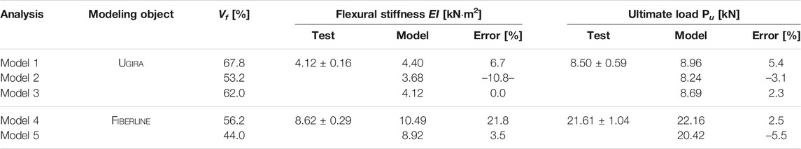
TABLE 4. Accuracy analysis of numerical models.
The modeling results (Table 4) demonstrate that the assumed fiber volume Vf affects the predictions. Accounting for the variation of the experimental outcomes, the significant errors (in the statistical sense) are characteristic of the Ugira profile stiffness results. Furthermore, the prediction error exceeds the Vf assessment error (compare the EI results of Model 1 and Model 2 with the reference Model 3). The analysis of the Fiberline predictions identifies a similar trend—inadequate Vf assumption increases the EI prediction error from 3.5% (Model 5) to 21.8% (Model 4). However, the opposite tendency in the ultimate load prediction exists—the fiber content increase remedies the Pu predictions. That can be a consequence of the effect of the additional fibers identified during the heating tests (the “Fiber Content Analysis” section) regarding the manufacturer specified content.
An efficient balance between the prediction accuracy and computation time characterizes the developed FE approach that does not require specific descriptions of reinforcement geometry and refined meshes necessary for modeling the discrete fibers (Garnevičius et al., 2020). The Atena software also allows smearing the reinforcement in different directions to represent the complex fiber architecture (the “Finite Element Model” section). Unfortunately, the manufacturer provides no sufficient information to develop such a model. Therefore, the updated datasheets must include information about the fiber percentage and orientation in different directions. The proposed modeling methodology can also determine the fiber efficiency in reinforcing the polymer matrix useful for developing efficient structural components.
Non-Linear Behavior of GFRP Profiles
The pultrusion direction governs the mechanical resistance of FRP profiles (Correia, 2013). In three-point bending, the center load stresses the profile in both pultrusion and transverse directions. Under such loading conditions, the analogs metallic SHS profiles face the web crippling because of the web yielding or web buckling failure mechanisms. The failure mode depends on the relative web stiffness described in terms of the slenderness factor (Misiunaite et al., 2020):
where b and t are the width and thickness of the flat web part; fy and E are the yield strength and elastic modulus of the material.
For isotropic materials, the principal stress and principal strain orientations coincide at a 45° angle. This condition is not valid for orthotropic FRP profiles, where the pultrusion direction does not describe the principle stress-strain distribution (Insausti et al., 2020). Moreover, a low shear modulus of FRP composites (regarding the steel) causes intensive shear deformations of short beams also known, as shearing strain (Peng et al., 2020). The excessive shear strains define a central problem in pultruded FRP beams because of the minimal contribution of longitudinal fibers (Correia et al., 2011; Wu et al., 2019; Almeida-Fernandes et al., 2021). The misbalance in longitudinal and transverse material properties leads to non-proportional angular distortion and shearing failure of the web, shown in Figure 9. Thus, the web crippling mechanism of the pultruded GFRP SHS profile combines the web-flange junction’s separation and the web shearing/crushing.
The strain distribution within the cross-section height of the GFRP SHS beam is non-linear with the increase of inelastic deformations. Moreover, the Navier-Bernoulli hypothesis is not valid at already low loading levels (e.g., 3 kN, Figure 15A). That is the consequence of the synergetic effect of the tensile and compressive elastic modulus distinction in the GFRP composite (Insausti et al., 2020), and the slender filaments instability in compression causes the onset of buckling in the compression flange (Correia et al., 2011; Misiunaite et al., 2020). However, the proposed approach to FE modeling based on the smeared reinforcement concept adequately covers both above material aspects characteristic of the pultruded GFRP composites.
Possible Improvement of the Fibers Efficiency
The Fiberline fibers have uneven rough surfaces with small particles having an approximate 1–3 μm size (Figures 4A,B) that can potentially improve the bond performance with a polymer matrix (Papon et al., 2020). On the contrary, an untreated glassily surface is characteristic of the Ugira samples (Figures 4C,D). That defines the object for further modifications.
Figures 5, 6 show the SEM images of the web and corner microsections normal to the pultrusion direction. The reference Fiberline specimens demonstrate a more dense microstructure without visible defects of the fiber contact zones with polymer matrix than the Ugira samples do. With the increased fiber diameter, the interactional defects observed in the alternative specimens (Figures 5C,D, 6C,D) can further affect the bond performance and reduce the efficient fiber fraction Vf,eff of the Ugira profiles identified in the “Fiber Efficiency Analysis” section. The bonding mechanisms identified in reinforced concrete composites (Gribniak et al., 2016, 2020; Rimkus and Gribniak, 2017) support the above inference—the same reinforcement area in a higher number of bars (with reduced bar diameter) can substantially improve the bond performance of the composite material. Thus, the fiber diameter reduction for the same fiber-reinforcement fraction can potentially increase its efficiency.
Conclusions
This investigation focuses on the mechanical performance of pultruded glass fiber-reinforced polymer (GFRP) profiles developed for structural applications. Two GFRP square hollow section profiles available at the European market (Fiberline, Denmark and Ugira, Lithuania) define the research object. Within the framework of this study, a simplified finite element (FE) model is developed based on the smeared reinforcement concept to predict the stiffness and load-bearing capacity of the profiles. The proposed FE approach is also used to analyze the fiber efficiency in reinforcing a polymer matrix. Scanning electron microscopy (SEM) relates the composite microstructure and the mechanical performance of the selected profiles. The following essential findings result from this study:
1) An efficient balance between the prediction accuracy and computation time characterizes the developed FE approach—the ultimate load prediction error does not exceed 5%. The model is also suitable for estimating the efficient reinforcement fraction when experimental parameters describe the glass filament and polymer matrix constitutive models. The model’s ability to resist mechanical load proportional to the dry filaments’ content defines the reinforcement efficiency. The efficient mass percentage of the Ugira profiles is equal to 71.0% that is 4% below the declared one. Still, the latter value aligns with the fiber percentage defined during the heating tests in this study.
2) SEM determined a possible improvement way of the Ugira profile’s mechanical performance. A decrease in the filament diameter and fiber surface treatment can potentially increase the reinforcement efficiency.
3) A tensile coupon test is inapplicable for constitutive modeling GFRP composite. In this study, the fiber efficiency estimation error has reached 40% applying this standard test result for the modeling; the material characterization error increases with the decrease of the sample size, i.e., with the coupon boundary cut-side area increase regarding the sample cross-section dimensions.
4) This study questions the clarity of the producer datasheets. The complex internal architecture of the Fiberline composite is a possible explanation of the inconsistency between the declared (≈60%) and measured (71.0%) fiber mass contents. However, the producer does not provide any detailed information on fiber fraction quantification. Furthermore, the mechanical parameters essential for the numerical modeling (i.e., density, strength, and elastic modulus of the E-glass filaments and polyester matrix) are also missed in the datasheets.
Data Availability Statement
The raw data supporting the conclusions of this article will be made available by the authors, without undue reservation.
Author Contributions
Conceptualization, VG and AR; methodology, VG and AŠ; software, AR; validation, VG, LP, and RB; formal analysis, IM; investigation, LP, AR, and RB; resources, VG; data curation, MG; writing—original draft preparation, VG and MG; writing—review and editing, VG and AR; visualization, AR, LP, and RB; supervision, VG and AŠ; project administration, AR; funding acquisition, VG.
Funding
This study has received funding from the European Regional Development Fund (Project No. 01.2.2-LMT-K-718-03-0010) under a grant agreement with the Research Council of Lithuania (LMTLT). Vilnius Gediminas Technical University covered the APC.
Conflict of Interest
The authors declare that the research was conducted in the absence of any commercial or financial relationships that could be construed as a potential conflict of interest.
Publisher’s Note
All claims expressed in this article are solely those of the authors and do not necessarily represent those of their affiliated organizations, or those of the publisher, the editors and the reviewers. Any product that may be evaluated in this article, or claim that may be made by its manufacturer, is not guaranteed or endorsed by the publisher.
References
Alaedini, S., Kabir, M. Z., and Al-Mahaidi, R. (2021). Stability Performance of Thin-Walled Pultruded Beams with Geometric Web-Flange Junction Imperfections. J. Building Eng. 33, 101549. doi:10.1016/j.jobe.2020.101549
Almeida-Fernandes, L., Correia, J. R., and Silvestre, N. (2021). Effect of Fibre Layup and Bearing Length on the Web-Crippling Behaviour of Pultruded GFRP Profiles. Compos. Structures 267, 113884. doi:10.1016/j.compstruct.2021.113884
Bazli, M., and Abolfazli, M. (2020). Mechanical Properties of Fibre Reinforced Polymers Under Elevated Temperatures: An Overview. Polymers 12, 2600. doi:10.3390/polym12112600
Cai, J., Pan, J., and Zhou, X. (2017). Flexural Behavior of Basalt FRP Reinforced ECC and concrete Beams. Construction Building Mater. 142, 423–430. doi:10.1016/j.conbuildmat.2017.03.087
Cervenka, V. (2002). “Computer Simulation of Failure of Concrete Structures for Practice,” In Proceedings of the First fib Congress Concrete Structures in 21 Century (Osaka, Japan: Keynote lecture in Session 13), 289–304.
Chen, D., Sun, G., Meng, M., Jin, X., and Li, Q. (2019). Flexural Performance and Cost Efficiency of Carbon/basalt/glass Hybrid FRP Composite Laminates. Thin-Walled Structures 142, 516–531. doi:10.1016/j.tws.2019.03.056
Correia, J. R., Branco, F. A., Silva, N. M. F., Camotim, D., and Silvestre, N. (2011). First-Order, Buckling and Post-Buckling Behaviour of GFRP Pultruded Beams. Part 1: Experimental Study. Comput. Structures 89 (21-22), 2052–2064. doi:10.1016/j.compstruc.2011.07.005
Correia, J. R. (2013). “Pultrusion of Advanced Fibre-Reinforced Polymer (FRP) Composites,” In Advanced Fibre-Reinforced Polymer (FRP) Composites for Structural Applications, Editors J. Bai (Cambridge: Woodhead Publishing), 207–251. doi:10.1533/9780857098641.2.207
El-Wazery, M. S., El-Elamy, M. I., and Zoalfakar, S. H. (2017). Mechanical Properties of Glass Fiber Reinforced Polyester Composites. Int. J. Appl. Sci. Eng. 14 (3), 121–131. doi:10.6703/IJASE.2017.14(3).121
Eskandari, S., Andrade Pires, F. M., Camanho, P. P., Cui, H., Petrinic, N., and Marques, A. T. (2019). Analyzing the Failure and Damage of FRP Composite Laminates under High Strain Rates Considering Visco-Plasticity. Eng. Fail. Anal. 101, 257–273. doi:10.1016/j.engfailanal.2019.03.008
Feo, L., Mosallam, A. S., and Penna, R. (2013). Mechanical Behavior of Web-Flange Junctions of Thin-Walled Pultruded I-Profiles: An Experimental and Numerical Evaluation. Composites B: Eng. 48, 18–39. doi:10.1016/j.compositesb.2012.11.001
Fiberline (2021). General Properties for P2600. Fiberline Datasheet. Fredericia: Fiberline Building Profiles A/S.
Garnevičius, M., Plioplys, L., Ng, P.-L., Chu, S., and Gribniak, V. (2020). Investigation and Improvement of Bond Performance of Synthetic Macro-Fibres in Concrete. Materials 13, 5688. doi:10.3390/ma13245688
Gribniak, V., Kaklauskas, G., Hung Kwan, A. K., Bacinskas, D., and Ulbinas, D. (2012). Deriving Stress-Strain Relationships for Steel Fibre Concrete in Tension from Tests of Beams with Ordinary Reinforcement. Eng. Structures 42, 387–395. doi:10.1016/j.engstruct.2012.04.032
Gribniak, V., Kaklauskas, G., Idnurm, S., and Bačinskas, D. (2010). Finite Element Mesh Size Effect on Deformation Predictions of Reinforced concrete Bridge Girder. Baltic J. Road Bridge Eng. 5 (1), 19–27. doi:10.3846/bjrbe.2010.03
Gribniak, V., Misiūnaitė, I., Rimkus, A., Sokolov, A., and Šapalas, A. (2019). Deformations of FRP-Concrete Composite Beam: Experiment and Numerical Analysis. Appl. Sci. 9 (23), 5164. doi:10.3390/app9235164
Gribniak, V., Pérez Caldentey, A., Kaklauskas, G., Rimkus, A., and Sokolov, A. (2016). Effect of Arrangement of Tensile Reinforcement on Flexural Stiffness and Cracking. Eng. Structures 124, 418–428. doi:10.1016/j.engstruct.2016.06.026
Gribniak, V., Rimkus, A., Pérez Caldentey, A., and Sokolov, A. (2020). Cracking of Concrete Prisms Reinforced with Multiple Bars in Tension-The Cover Effect. Eng. Structures 220, 110979. doi:10.1016/j.engstruct.2020.110979
Gribniak, V., Rimkus, A., Torres, L., and Jakstaite, R. (2017). Deformation Analysis of Reinforced Concrete Ties: Representative Geometry. Struct. Concrete 18 (4), 634–647. doi:10.1002/suco.201600105
Gribniak, V. (2020). Special Issue “Advanced Composites: From Materials Characterization to Structural Application”. Materials 13, 5820. doi:10.3390/ma13245820
Gribniak, V., Sultani, H. A., Rimkus, A., Sokolov, A., and Torres, L. (2021). Standardised Quantification of Structural Efficiency of Hybrid Reinforcement Systems for Developing Concrete Composites. Compos. Structures 274, 114357. doi:10.1016/j.compstruct.2021.114357
Grund, D., Orlishausen, M., and Taha, I. (2019). Determination of Fiber Volume Fraction of Carbon Fiber-Reinforced Polymer Using Thermogravimetric Methods. Polym. Test. 75, 358–366. doi:10.1016/j.polymertesting.2019.02.031
He, J., Liu, Y., Chen, A., and Dai, L. (2012). Experimental Investigation of Movable Hybrid GFRP and Concrete Bridge Deck. Construction Building Mater. 26 (1), 49–64. doi:10.1016/j.conbuildmat.2011.05.002
Insausti, N., Adarraga, I., Carbajal, N., and Mujika, F. (2020). Numerical Assessment of the Analytical Models Used to Determine Flexural and Shear Moduli in I-Beams when the Tensile and Compressive Moduli Are Different. Polym. Test. 81, 106154. doi:10.1016/j.polymertesting.2019.106154
Keller, T., and Schollmayer, M. (2004). Plate Bending Behavior of a Pultruded GFRP Bridge Deck System. Compos. Structures 64 (3-4), 285–295. doi:10.1016/j.compstruct.2003.08.011
Li, F., Zhang, D.-D., Zhao, Q.-L., and Deng, A.-Z. (2015). A Simple Analytical Solution for Predicting Deflection of a Hybrid FRP-Aluminum Modular Space Truss Bridge. J. Cent. South. Univ. 22, 4414–4425. doi:10.1007/s11771-015-2989-5
Mahboubi, S., and Shiravand, M. R. (2019). Failure Assessment of Skew RC Bridges with FRP Piers Based on Damage Indices. Eng. Fail. Anal. 99, 153–168. doi:10.1016/j.engfailanal.2019.02.010
Mandal, B., and Chakrabarti, A. (2018). Numerical Failure Assessment of Multi-Bolt FRP Composite Joints with Varying Sizes and Preloads of Bolts. Compos. Structures 187, 169–178. doi:10.1016/j.compstruct.2017.12.048
Misiūnaitė, I., Gribniak, V., Rimkus, A., and Jakubovskis, R. (2020). The Efficiency of Utilisation of High-Strength Steel in Tubular Profiles. Materials 13, 1193. doi:10.3390/ma13051193
Muc, A., Stawiarski, A., and Chwał, M. (2020). Design of the Hybrid FRP/concrete Structures for Bridge Constructions. Compos. Structures 247, 112490. doi:10.1016/j.compstruct.2020.112490
Papapetrou, V. S., Tamijani, A. Y., Brown, J., and Kim, D. (2019). Design Optimization of Hybrid FRP/RC Bridge. Appl. Compos. Mater. 26 (1), 249–270. doi:10.1007/s10443-018-9691-3
Papon, E. A., Haque, A., and Spear, S. K. (2020). Effects of Functionalization and Annealing in Enhancing the Interfacial Bonding and Mechanical Properties of 3D Printed Fiber-Reinforced Composites. Mater. Today Commun. 25, 101365. doi:10.1016/j.mtcomm.2020.101365
Peng, Z., Wang, X., and Wu, Z. (2020). A Bundle-Based Shear-Lag Model for Tensile Failure Prediction of Unidirectional Fiber-Reinforced Polymer Composites. Mater. Des. 196, 109103. doi:10.1016/j.matdes.2020.109103
Rimkus, A., Cervenka, V., Gribniak, V., and Cervenka, J. (2020). Uncertainty of the Smeared Crack Model Applied to RC Beams. Eng. Fracture Mech. 233, 107088. doi:10.1016/j.engfracmech.2020.107088
Rimkus, A., and Gribniak, V. (2017). Experimental Investigation of Cracking and Deformations of concrete Ties Reinforced with Multiple Bars. Construction Building Mater. 148, 49–61. doi:10.1016/j.conbuildmat.2017.05.029
Robinson, M. J., and Melby, I. H. (2015). Effects of Bonding in Short-Span Rectangular Concrete Filled GFRP Tubes. Compos. Structures 133, 131–139. doi:10.1016/j.compstruct.2015.07.105
Siwowski, T., Kulpa, M., Rajchel, M., and Poneta, P. (2018). Design, Manufacturing and Structural Testing of All-Composite FRP Bridge Girder. Compos. Structures 206, 814–827. doi:10.1016/j.compstruct.2018.08.048
Siwowski, T., Rajchel, M., and Kulpa, M. (2019). Design and Field Evaluation of a Hybrid FRP Composite - Lightweight Concrete Road Bridge. Compos. Structures 230, 111504. doi:10.1016/j.compstruct.2019.111504
Thorhallsson, E. R., Hinriksson, G. I., and Snæbjörnsson, J. T. (2017). Strength and Stiffness of Glulam Beams Reinforced with Glass and Basalt Fibres. Composites Part B: Eng. 115, 300–307. doi:10.1016/j.compositesb.2016.09.074
Tu, J., Xie, H., Gao, K., Li, Z., and Zhang, J. (2019). Durability Prediction of GFRP Rebar Based on Elastic Modulus Degradation. Front. Mater. 6, 258. doi:10.3389/fmats.2019.00258
Votsis, R. A., Stratford, T. J., Chryssanthopoulos, M. K., and Tantele, E. A. (2017). Dynamic Assessment of a FRP Suspension Footbridge Through Field Testing and Finite Element Modelling. Steel Compos. Struct. 23 (2), 205–215. doi:10.12989/scs.2017.23.2.205
Wang, H.-P., Feng, S.-Y., Gong, X.-S., Guo, Y.-X., Xiang, P., Fang, Y., et al. (2021). Dynamic Performance Detection of CFRP Composite Pipes Based on Quasi-Distributed Optical Fiber Sensing Techniques. Front. Mater. 8, 683374. doi:10.3389/fmats.2021.683374
Wu, C., and Bai, Y. (2014). Web Crippling Behaviour of Pultruded Glass Fibre Reinforced Polymer Sections. Compos. Structures 108, 789–800. doi:10.1016/j.compstruct.2013.10.020
Wu, C., Zhang, L.-T., Bai, Y., and Zhao, X.-L. (2019). Web Crippling Behavior of Pultruded GFRP Channel Sections Under Transverse Bearing Load. Compos. Structures 209, 129–142. doi:10.1016/j.compstruct.2018.10.067
Xing, J., Du, C., He, X., Zhao, Z., Zhang, C., and Li, Y. (2019). Finite Element Study on the Impact Resistance of Laminated and Textile Composites. Polymers 11 (11), 1798. doi:10.3390/polym11111798
Yang, Y., Wang, X., and Wu, Z. (2020). Long-Span Cable-Stayed Bridge with Hybrid Arrangement of FRP Cables. Compos. Structures 237, 111966. doi:10.1016/j.compstruct.2020.111966
Ye, Z., Zhao, D., Sui, L., Huang, Z., and Zhou, X. (2020). Behaviors of Large-Rupture-Strain Fiber-Reinforced Polymer Strengthened Reinforced Concrete Beams under Static and Impact Loads. Front. Mater. 7, 578749. doi:10.3389/fmats.2020.578749
Yuan, Y., Yao, X., Niu, K., Liu, B., and Wuyun, Q. (2019). Compressive Failure of Fiber Reinforced Polymer Composites by Imperfection. Composites A: Appl. Sci. Manufacturing 118, 106–116. doi:10.1016/j.compositesa.2018.12.017
Zhang, D., Li, F., Shao, F., and Fan, C. (2019a). Evaluation of Equivalent Bending Stiffness by Simplified Theoretical Solution for an FRP-Aluminum Deck-Truss Structure. KSCE J. Civ. Eng. 23, 367–375. doi:10.1007/s12205-018-1093-4
Zhang, D., Lv, Y., Zhao, Q., and Li, F. (2019b). Development of Lightweight Emergency Bridge Using GFRP-Metal Composite Plate-Truss Girder. Eng. Structures 196, 109291. doi:10.1016/j.engstruct.2019.109291
Keywords: GFRP profile, microstructure, fiber volume, deformations, load-bearing capacity, finite element modeling
Citation: Gribniak V, Rimkus A, Plioplys L, Misiūnaitė I, Garnevičius M, Boris R and Šapalas A (2021) An Efficient Approach to Describe the Fiber Effect on Mechanical Performance of Pultruded GFRP Profiles. Front. Mater. 8:746376. doi: 10.3389/fmats.2021.746376
Received: 23 July 2021; Accepted: 24 August 2021;
Published: 06 September 2021.
Edited by:
Denvid Lau, City University of Hong Kong, Hong Kong, SAR ChinaReviewed by:
Zechuan Yu, Wuhan University of Technology, ChinaGuan Lin, Hong Kong Polytechnic University, Hong Kong, SAR China
Copyright © 2021 Gribniak, Rimkus, Plioplys, Misiūnaitė, Garnevičius, Boris and Šapalas. This is an open-access article distributed under the terms of the Creative Commons Attribution License (CC BY). The use, distribution or reproduction in other forums is permitted, provided the original author(s) and the copyright owner(s) are credited and that the original publication in this journal is cited, in accordance with accepted academic practice. No use, distribution or reproduction is permitted which does not comply with these terms.
*Correspondence: Viktor Gribniak, VmlrdG9yLkdyaWJuaWFrQHZpbG5pdXN0ZWNoLmx0