 Huiqin Chen*
 Sizhe He
- School of Materials Science and Engineering, Taiyuan University of Science and Technology, Taiyuan, China
Void-type defects in heavy forgings deteriorate their mechanical properties and service life. In this work, the evolutions of a pre-crack closure and the healing and mechanical properties of FeCrNi polycrystalline samples are assessed under different loading conditions using molecular dynamics simulation. The stress–strain curves show that the sample with interface exhibits higher Young’s modulus and yield strength than those with cracks, despite the loading conditions. These results imply that samples under compression loading have a higher ability to resist plasticity, while the shear stress facilitates plastic flow. Crack closure and healing occur under compression stress by dislocation-dominant plastic deformation, while the crack length shrinks and the crack tips expand along grain boundaries (GBs) and the interface because of its higher stress under shear loading. Dislocation activities, including dislocation emission, slip, and interactions with cracks, grain boundaries, and dislocations, contribute to the plasticity of the specimen under compressive loading. In addition to dislocation activities, grain boundary slip, grain rotation, and twinning are potential plastic-deformation mechanisms under shear loading.
Introduction
Void-type defects (such as shrinkage cavities, porosities, and cracks) in heavy forgings are inevitable during manufacturing and application of non-uniform solidification of the materials during casting, which can severely deteriorate the product strength and service life. In the manufacturing process, it is important to eliminate these internal voids through an appropriate molding process. In general, eliminating voids inside large ingots includes two stages: void closure and healing of closed void surfaces (Qiu et al., 2020). The void closure process is to contact the internal surface of void (Zhang et al., 2009). Crack closure and healing are mainly achieved through thermoplastic deformation (Chen and Lin, 2013; Wang et al., 2015) and heat treatment (Qiu et al., 2020). Thermoplastic deformation has been widely used in actual production because of its feasibility and high efficiency.
A criterion for void closure in large ingots during hot forging was proposed, based on numerous numerical computations, by developing a cell model, and the effects of the Norton exponent, remote stress triaxiality, and remote effective strain were considered (Zhang et al., 2009). Evolution behaviors of an elliptic–cylindrical void were analyzed by the representative volume element model incorporated into the finite element (FE) method by considering void deformation and rotation; the results showed that deviation stress significantly influences both void radius and void orientation (Feng et al., 2017). This method was also applied to study the evolution of dilute ellipsoidal voids under triaxial loading conditions, with void radius strain rate and volume strain rate expressed as functions of void shape index, macroscopic stress, and strain rate. In the process of large compression deformation, the predicted results of this model were in good agreement with the analytical solution, experimental measurements, and numerical simulation results (Feng et al., 2016). The void closure efficiency of different cogging processes in large ingots conducted using a 3-D void evolution model suggested that compression perpendicular to the longer principal axis of the prolate void provides a higher void-closure efficiency than that aligned with this direction. Surface bonding experiments showed that void defects after void closure are favorable to eliminate under the conditions of higher pressure, temperature, and long holding time (Feng et al., 2016). Evolution mechanisms for spherical or spheroidal voids during hot working were studied by varying the initial void size, aspect ratio, and void positions by theoretical and experimental analysis (Chen and Lin, 2013). Recently, the evolution of nanocracks induced by plastic deformation in single crystals and bicrystalline copper was investigated using molecular dynamics simulations. The results showed that compressive stress induced by defects such as dislocation, 9R phases, and deformation twinning drives crack closure (Fang et al., 2017). Under shear stress, dislocation emission from the crack tip leads to crack closure through the dislocation shielding effect and atomic diffusion, and crack healing largely depends on crystallographic orientation and the direction of external loading (Li et al., 2015). Elevated temperature facilitates crack healing because atomic diffusion occurs (Wei et al., 2004; Wei et al., 2013); furthermore, compression pressure, irrespective of biaxial and uniaxial loading, promotes crack healing and leads to a more uniform distribution of defects after healing.
The evolution behaviors of voids of different sizes during the hot rolling process were investigated by FE simulation and experimental observation, which showed that their shapes change from spherical to ellipsoidal and then become irregular. The two surfaces of the void bond together after the last rolling pass (Huang et al., 2014; Wang et al., 2015). Crack healing and the recovery percentage of the impact properties of internal crack healing in SA508 steel were studied under various deformation modes and under quenching and tempering. The study addressed the fact that the recovery of impact properties by multi-pass thermal deformation is lower than that by uniaxial compression at 950°C and 1,050°C, and that a newly formed Z-type grain belt is observed in the crack healing zone, exhibiting higher resistance to dynamic load at 1,150°C (Qiu et al., 2020). Crack closure induced by laser peening (LP) and its effects on the fatigue-life extension of an Al alloy with initial fatigue crack were investigated, and the results showed that the fatigue life of treated samples is higher than for those not treated and that LP-induced plastic deformation around a pre-crack contributes to crack closure and fatigue-life extension (Hu et al., 2020). Although much effort has been made theoretically and experimentally, a full understanding of crack closure, closure healing evolution, and the mechanical behaviors of samples with cracks under different loads is still absent. Fortunately, the molecular dynamics technique can provide meaningful insights into the mechanical behaviors of FeCrNi polycrystalline samples, due to its capacity for high spatiotemporal processes and in situ observation.
In this work, compression and shear tests were conducted for FeCrNi polycrystals with interfaces and nanocracks using molecular dynamics simulation. A focus was placed on exploring the evolutions of crack closure and healing and the plastic-deformation behaviors of polycrystalline samples. This work may contribute to a better understanding of the plastic-deformation characteristics of nanoscale polycrystalline samples and to practical engineering processing.
Materials and methods
In this work, polycrystalline austenitic FeCrNi samples with additions of Cr wt. 18% (at. 19%) and Ni wt. 9% (at. 8.7%) were prepared using Atomsk software (Hirel, 2015). The size of the polycrystalline sample was 82 × 82 × 10 nm3 and contained 1094283 Cr atoms, 788808 Ni atoms, and 3877596 Fe atoms with a lattice parameter of 0.35 nm, as shown in Figure 1. The Cr and Ni atoms were randomly distributed within the samples as substitutional atoms. One sample, termed an interface-containing sample, consisted of 28 grains in various crystallographic orientations, among which eight intact grains were constructed around the interface located in the middle of the sample. The other sample considered had a prefabricated crack placed in the interface, with two triangular GBs on the interface selected as the beginning and end of the prefabricated crack. By erasing atoms, a prefabricated crack with a length of 51 nm and a width (about 2.8 nm) of about six times the average width of the GBs appeared within the sample. The simulation process can was divided into two stages: relaxation and mechanical-loading stages. Before the loading, the designed samples were relaxed to local minimum energy by the steepest-descent algorithm and then equilibrated with a canonical ensemble (NVT) with a Nose–Hoover thermostat for 90 ps at a constant temperature of 300 K; the constant pressure/constant temperature ensemble (NPT) was then used during compression and shear loading. Compressive force was applied parallel to the y-axis direction, while shear force was applied parallel to the x-axis direction with a strain rate of 2.8 × 10⁸ s−1 and a time step of 1.0 fs. Periodic boundary conditions were applied in all three directions.
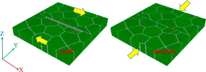
FIGURE 1. Schematic of samples with crack and interface loaded under compression and shear stress.
Atomic interactions in the FeCrNi samples were described by the potential function of the embedded atom method (EAM), which describes austenite’s properties in a large concentration range based on the ab initio calculation (Bonny et al., 2011). This potential has been successfully used to describe dislocation movement (Fan et al., 2020), the relationship between solute segregation and GB state (Barr et al., 2014), and high-energy collision cascades coupled with ab initio calculation in FeCrNi alloys (Béland et al., 2017). In this work, the visualization and analysis of polycrystalline samples was performed using OVITO software (Polak, 2022). The simulations were performed by the Large-scale Atomic Parallel Simulator (LAMMPS) (Li et al., 2021).
Results and discussions
Austenitic FeCrNi samples have a face-centered cubic (FCC) crystal structure, with more slip systems and a greater coordinated deformation capacity. However, if the GBs interact with interfaces and cracks during loading deformation, the dislocation slip motion and propagation are easily hindered, which affects the mechanical properties and plastic-deformation behaviors of materials. Stress–strain curves, which provide useful information about the samples’ responses to external force, are the most intuitive method for identifying the mechanical properties of austenitic materials during loading. Therefore, the stress–strain curves of the polycrystalline samples with interface and crack during compression and shear are shown in Figure 2. The curves illustrate that applied stress increases dramatically, and then the samples yield different yield stresses depending upon their characteristics and loading conditions; subsequently, the stress first decreases rapidly and then increases steadily under compression. The stress increases slightly after yielding under shear. In addition, the yield strength of the sample with interface was 5.5 GPa, which is about four times higher than that with crack under compression. A similar result was additionally seen under shear but with lower yield strength (e.g., the values of yield strength are 2.0 GPa and 0.9 GPa for samples with interface and crack, respectively). It was observed that the elastic modulus (reflected by the slope of stress–strain curves in the elastic deformation stage) for samples with interface was much higher than for those with crack under the same loading conditions. These outcomes indicate that the interface-containing sample has a higher resistance to plastic deformation than that with crack.
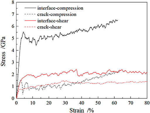
FIGURE 2. Stress–strain curves under various loading conditions.
Analysis of pre-crack closure
Cracks and other void-type defects are defects caused by the loss of a large number of atoms under the action of stress (Kardani and Montazeri, 2018) and are inevitable in the manufacture of heavy ingots. The existence of a nanocrack deteriorates the mechanical properties and leads to early failure of the final product. In this work, the crack closure process of the sample during compression was carefully explored. The evolutions of the atomic configuration of the sample during compression are shown in Figure 3, with the sample with interface considered for comparison. By comparing the atomic configuration of the two kinds of samples at the same strain rate, it was found that the upper and lower interfaces of the middle part of the crack became closed and contacted each other when the strain reached 7.6%. Voids appeared at both ends of the crack and shrank gradually, finally disappearing with increasing strain. That is to say, crack closure takes place as the compression strain increases, up to 15.2%. With the progress of compression, the relatively straight interface newly generated by crack closure becomes curved due to plastic deformation and is dominated by dislocations, implying that crack healing occurs. As for the sample with interface, the original long and straight shape varied to a sawtooth shape with the accumulation of strain, and some smaller grains on both sides of the interface continued to aggregate with the surrounding large grains, resulting in the coarsening of the grains. For example, grains G1, G2, and G3 within the sample with interface merged into a new grain (recorded as G123) when the strain reached 23.1%, as illustrated in Figure 4. A small decrease was observed in the atomic arrangement between each other grain for G1, G2, and G3 at 0.0%, and the distinction decreases with strain and finally vanished at 23.1%, implying that slight grain rotation occurs through lattice torsion under compression loading.
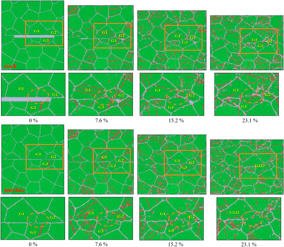
FIGURE 3. Deformation evolutions of atomic configuration under compression versus strain (atoms are colored according to the crystalline structure based on dislocation extraction analysis, DXA). Green, red, and white represent the face-centered cubic (FCC) crystal structure, hexagonal close-packed (HCP) crystal structure, grain boundaries, and other unknown structures, respectively).
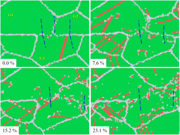
FIGURE 4. Crystallographic orientation changings of G1, G2, and G3 grains within the sample with the interface versus strain (atoms are colored similar to Figure 3, and blue dotted lines present directions of atomic arrangement).
To further explore the crack closure mechanism, von Mises stress analysis as a function of strain was performed in Figure 5. The value of shear stress was observed to increase with increasing compression strain for the two samples, and the stress at GBs and within the grain interior of the interface-containing sample were significantly higher than in samples with cracks because of higher applied stress at the same strain (Figure 2). Before the crack is closed, the stress is primarily concentrated in the exterior of crack tips, especially in trigeminal GB regions, where GB migration and stress relaxation are more likely to occur. Stress distribution after crack closure is relatively homogeneous, and a similar distribution also happens within the sample with interface.
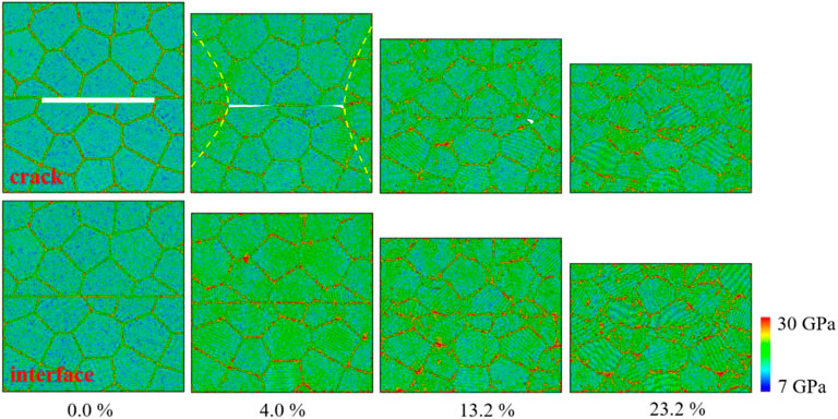
FIGURE 5. Cross-section snapshots of von Mises stress distribution at different compression strains (yellow dotted lines denote stress-concentrated areas).
Analysis of pre-crack propagation
To investigate the load-dependent crack behaviors of polycrystalline samples, shear force was applied to both crack and interface samples, and the deformation evolutions versus shear strain are shown in Figure 6. It was found that with the increase of strain, more stacking faults (SFs, determined as HCP atoms) were present from the two crack tips and then extended heterogeneously along the crack plane. The appearance of SFs means that partial dislocation movement is activated, and its degree is enhanced with increasing shear strain. Though the total length of the crack seems to decrease as shear continues, the surfaces of the crack become curved due to interface emigration induced by interactions between dislocations and surfaces. The number of crack tips gradually extends to 4 along the surrounding GBs (upper and lower sides of the crack), instead of the front of the crack tips, as the shear strain reaches 74.7%, which has also been theoretically and experimentally studied in other work (Li and Jiang, 2019; Li et al., 2021). As for the interface-containing sample, the SFs mainly appeared within the grains close to the interface at a strain of 10.5% and then expanded significantly around the entire sample; the detailed variations of SF atoms are given as follows. It is worth noting that grain rotation occurs synergistically along the direction of the shear load to the sample with interface to compensate for the increasing shear strain.
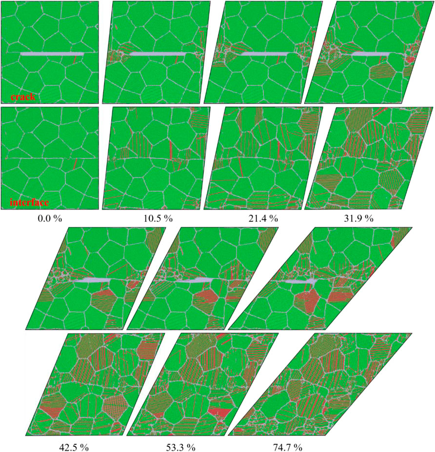
FIGURE 6. Atomic configuration of deformation evolutions under shear versus strain (atoms are colored according to the crystalline structure based on DXA method; green, red, and white represent the face-centered cubic [FCC] crystal structure, hexagonal close-packed [HCP] crystal structure, grain boundaries, and other unknown structures, respectively).
The corresponding evolution of von Mises stress distribution as a function of shear strain is illustrated in Figure 7 and indicates that variations of stress are similar and comparable to those under compression, except for the sample with crack, where shear stress is mainly concentrated near two crack tips (including GBs and interior grains), as shown by the yellow dotted line in Figure 7. This indicates again that the shear stress distribution follows changes in atomic configurations, as shown in Figure 6.
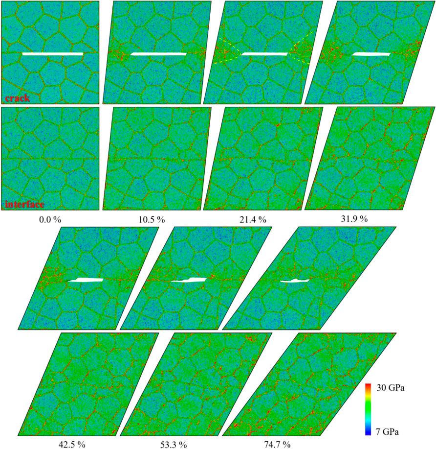
FIGURE 7. Cross-section snapshots of von Mises stress distribution at different shear strains (yellow dotted lines denote stress-concentrated areas.).
Analysis of plastic-deformation mechanisms
It is generally accepted that the dominant plastic-deformation mechanisms for crystalline metals are dislocation activities and twinning (Shi et al., 2018; Sun et al., 2019; Shi et al., 2020), which is different from those for amorphous materials (Spaepen, 1977; Argon, 1979; Chen et al., 2018a; Chen et al., 2018b; Chen et al., 2019; Chen et al., 2020) and semiconductors (Sun et al., 2014; Shi et al., 2017; Han et al., 2019; Sun et al., 2020). Therefore, detailed variations of dislocation length determined by the DXA analysis method and of twinning boundaries atoms obtained by coordinate number during compression and shear load are given in Figure 8. It was found that with the increase of compressive strain, the perfect dislocation lengths of the two samples decreased sharply and then increased after reaching a minimum value when the strain was about 23%. However, according to the characteristics of the sample, the corresponding value under shear decreased steadily at different rates, that is, during shear deformation, and the length of perfect dislocations in the sample with crack was longer than that in the sample with interface, as shown in Figure 8A. The amount of Shockley partial dislocation increased almost linearly with increasing strain, and its values under compression were much higher than those under shear at the same strain. It is interesting to note that the Shockley dislocation length of the sample with interface was slightly lower than the counterpart with crack under compression, which reverses the changes under shear. During deformation, two Shockley partial dislocations slipping on different (111) planes interact and generate a stair-rod dislocation, which is unmovable and prevents the further slipping of the two partial dislocations. The trends for stair-rod dislocation during loading are similar to those of Shockley dislocation but with a much higher value for the sample with interface under shear loading. The HCP atoms, as determined by OVITO visualization software, include intrinsic stacking faults and extrinsic stacking faults. The intrinsic stacking faults appear as Shockley partial dislocation glides toward the contrary side of the grain, leaving two adjacent (111) planes of HCP atoms. The extrinsic stacking faults, which are created by two Shockley partial dislocations slipping through the grain on the adjacent planes, are two (111) planes of HCP atoms separated by a (111) plane of FCC atoms (Zhang et al., 2019). Consequently, the number variations of HCP atoms during loading are analyzed and shown in Figure 8D; their amount is enhanced with increasing strain, with the values for the sample with interface higher than those with crack, especially for the sample with interface under shear loading (e.g., it is 13 × 105 and is more than twice as high as that with crack at 45% strain). The number variations of twinning boundary (TB) atoms are illustrated in Figure 8E, indicating that the atoms increase slightly with strain, except for the sample with interface under shear loading, which is the highest among the others.
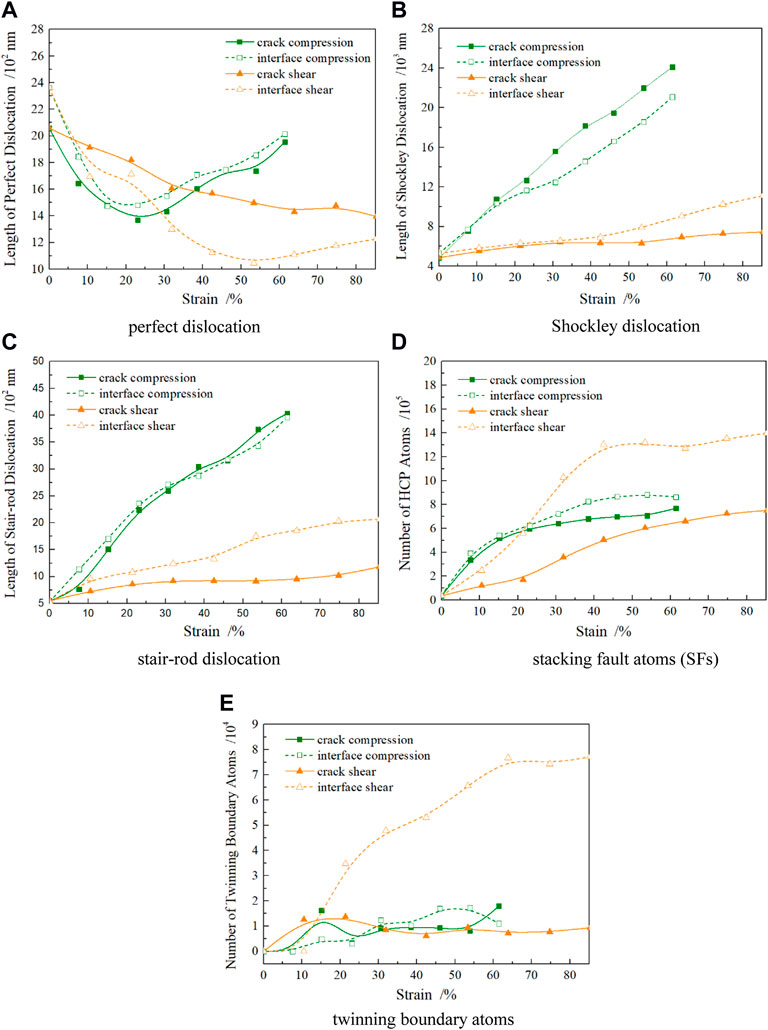
FIGURE 8. Variations of dislocation, SF atoms, and twinning boundary atoms versus strain, (A) perfect dislocation (B) Shockley dislocation, (C) stair-rod dislocation, (D) stacking fault atoms (SFs), and (E) twinning boundary atoms.
Since the GB in a polycrystalline sample is often an obstacle to crack propagation, dislocation accumulation occurs easily around GBs (Li and Jiang, 2019). The dislocation distribution after loading is demonstrated in Figure 9, which shows that massive Shockley partial dislocations and perfect dislocations are generated near GBs, while stair-rod dislocations appear within grain interiors during compression loading; thus, the dislocation density of GBs is much higher than within grain interiors. This implies again that during the compression process, a large number of dislocations are emitted from GBs, interfaces, and crack tips, where the atoms do not mismatch well and have higher stress concentrations, as shown in Figures 5,7. Then, the generated dislocations slip along glide planes and finally interact with opposite sides of the grains, crack, and dislocations, leading to an enhanced dislocation density as shown in Figure 8. Dislocation emission during shear loading mainly occurs at the two crack tips as well as in some individual grains where dislocation motion is activated earlier due to higher concentrated shear stress. Its degree of dislocation concentration is stronger for the sample with crack than for that with interface.
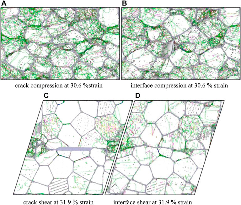
FIGURE 9. Dislocation distribution for different samples (blue lines represent perfect dislocations, green lines are partial dislocations, and pink lines are stair-rod dislocations), (A) crack compression at 30.6% strain, (B) interface compression at 30.6% strain, (C) crack shear at 31.9% strain, and (D) interface shear at 31.9% strain.
Considering that twinning and dislocation slip are the primary deformation mechanisms that dominate the plasticity of polycrystalline materials, the nucleation and growth of twins can not only hinder the movement of dislocation but can also increase deformation resistance and harden the materials. To more intuitively explore the quantity and distribution characteristics of twinning in samples with crack and interface under different loads, the evolutions of TB atoms were determined through coordination number analysis, as shown in Figure 10. It was found that the TB atoms appear when the strain increases to 15.2% of compressive strain and 21.4% of shear strain, respectively. TBs only take place within a small number of grains under compression, and the number of TB atoms increases slightly with growing compression strain. The TBs occur within some grains around crack tips, and the amount extends to grains along crack areas because of higher shear stress, as illustrated in Figure 7. However, a large number of micro-twins are generated at 21.4% for the sample with interface under shear loading in Figure 10B; its number, as well as twinning, grows significantly with strain, which is in accordance with the corresponding variations in Figure 8.
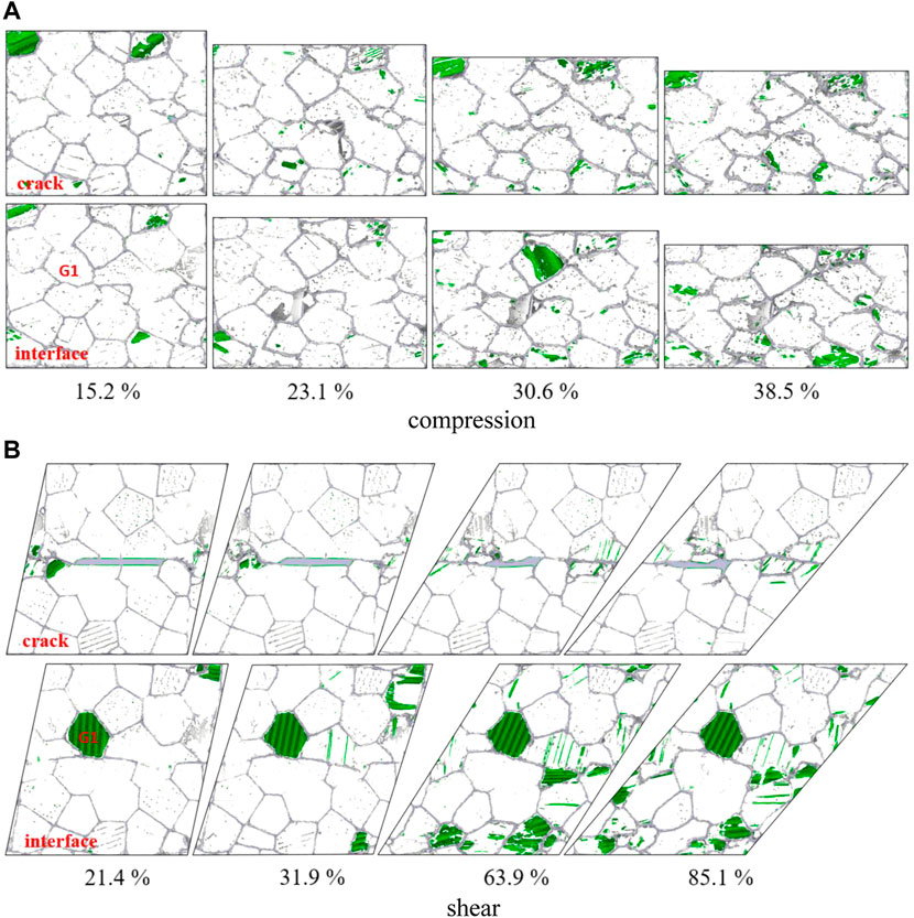
FIGURE 10. Evolutions of twinning boundary atoms as a function of strain (TB atoms are colored in green), (A) compression, (B) shear.
Based on the abovementioned analysis of deformation evolution and deformation mechanisms for samples with crack and interface, we know that perfect dislocation dissociation takes place with growing strain, resulting from increased Shockley dislocation density and declining length of perfect dislocation during the early compression process when the strain is less than 20%. The generation, movement, and interactions of massive partial dislocations hence lead to an increase in stair-rod dislocations and stacking fault atoms, as well as some twinning. Crack closure happens during dislocation-dominant plastic deformation under lower applied stress compared with the sample with interface. As compression proceeds, an enormous number of perfect dislocations are emitted from the newly generated interface and GBs where the stress is higher than the grain interior. Then the perfect dislocations separate into partial dislocations, causing significant increases in the lengths of partial dislocations and stair-rod dislocations due to dislocation interactions with interface and dislocations. The growing stair-rod dislocations and higher dislocation density, and their hindrance of dislocation motion, enhance the applied force for further compression plastic deformation. The compression stress-induced dislocation activities play significant parts in crack healing. During the shear process, the higher lengths of perfect dislocations, lower density of partial dislocations, and lower stair-rod dislocations and stacking faults for the sample with crack together imply that dislocation activities, as well as twinning, are substantially less than for the sample with interface. With these results, combined with the evolution of atomic configuration in Figure 6, the GB emigration, GB sliding along the existing interface, and crack tip extension along GBs play significant roles in shear plastic deformation for the sample with crack, while massive dislocation activities, twinning, and grain rotation contribute to plasticity for the sample with interface.
Conclusion
In this work, crack closure, healing evolutions, and mechanical behaviors of polycrystalline FeCrNi samples with pre-crack and interface were conducted using molecular dynamics simulation under varying loading conditions. The results were as follows:
1) As compression loading proceeds, the stress increases sharply until the material yield, then decreases, and subsequently continues to increase. The stress almost saturates after yielding under shear, exhibiting a much lower yield strength for the same sample than for compression.
2) Crack closure and healing take place under compression through dislocation-dominated plastic deformation, while the length of the crack shrinks and the crack tips expand along GBs and interface due to its higher stress under shear loading.
3) Dislocation activities, including dislocation emitting, gliding, and interactions with crack, GBs, and dislocations, contribute to the plasticity of the samples under compression. In addition to dislocation activities, GB gliding, grain rotation, and twinning are the underlying plastic-deformation mechanisms under shear loading.
Data availability statement
The original contributions presented in the study are included in the article/Supplementary Material; further inquiries can be directed to the corresponding authors.
Author contributions
HC: methodology, writing (review and editing), and funding acquisition. SH: investigation, formal analysis, and conceptualization. JC: methodology, writing (review and editing), and funding acquisition. FC: writing (original draft). SZ: investigation. YZ: formal analysis.
Funding
This study is supported by the National Natural Science Foundation of China (Grant number 51575372), Shanxi Scholarship Council of China (HGKY2019084), and the Doctor Funds of Taiyuan University of Science and Technology (20202004).
Conflict of interest
The authors declare that the research was conducted in the absence of any commercial or financial relationships that could be construed as a potential conflict of interest.
Publisher’s note
All claims expressed in this article are solely those of the authors and do not necessarily represent those of their affiliated organizations, or those of the publisher, the editors, and the reviewers. Any product that may be evaluated in this article, or claim that may be made by its manufacturer, is not guaranteed or endorsed by the publisher.
References
Argon, A. S. (1979). Plastic deformation in metallic glasses. Acta Metall. 27, 47–58. doi:10.1016/0001-6160(79)90055-5
Barr, C. M., Vetterick, G. A., Unocic, K. A., Hattar, K., Bai, X.-M., and Taheri, M. L. (2014). Anisotropic radiation-induced segregation in 316L austenitic stainless steel with grain boundary character. Acta Mater. 67, 145–155. doi:10.1016/j.actamat.2013.11.060
Béland, L. K., Tamm, A., Mu, S., Samolyuk, G. D., Osetsky, Y. N., Aabloo, A., et al. (2017). Accurate classical short-range forces for the study of collision cascades in Fe–Ni–Cr. Comput. Phys. Commun. 219, 11–19. doi:10.1016/j.cpc.2017.05.001
Bonny, G., Terentyev, D., Pasianot, R. C., Poncé, S., and Bakaev, A. (2011). Interatomic potential to study plasticity in stainless steels: The FeNiCr model alloy. Model. Simul. Mat. Sci. Eng. 19, 085008. doi:10.1088/0965-0393/19/8/085008
Chen, J., Fang, L., Sun, K., and Han, J. (2020). Creep behaviors of surface-modified silicon: A molecular dynamics study. Comput. Mater. Sci. 176, 109494. doi:10.1016/j.commatsci.2019.109494
Chen, J., Shi, J. Q., Chen, Z., Zhang, M., Peng, W. X., Fang, L., et al. (2019). Mechanical properties and deformation behaviors of surface-modified silicon: A molecular dynamics study. J. Mat. Sci. 54, 3096–3110. doi:10.1007/s10853-018-3046-1
Chen, J., Shi, J., Wang, Y., Sun, J., Han, J., Sun, K., et al. (2018). Nanoindentation and deformation behaviors of silicon covered with amorphous SiO2: A molecular dynamic study. RSC Adv. 8, 12597–12607. doi:10.1039/c7ra13638b
Chen, J., Shi, J., Zhang, M., Peng, W., Fang, L., Sun, K., et al. (2018). Effect of indentation speed on deformation behaviors of surface modified silicon: A molecular dynamics study. Comput. Mater. Sci. 155, 1–10. doi:10.1016/j.commatsci.2018.08.019
Chen, M.-S., and Lin, Y. C. (2013). Numerical simulation and experimental verification of void evolution inside large forgings during hot working. Int. J. Plasticity 49, 53–70. doi:10.1016/j.ijplas.2013.02.017
Fan, Y., Wang, W., Hao, Z., and Zhan, C. (2020). Work hardening mechanism based on molecular dynamics simulation in cutting Ni–Fe–Cr series of Ni-based alloy. J. Alloys Compd. 819, 153331. doi:10.1016/j.jallcom.2019.153331
Fang, Q., Li, J., Luo, H., Du, J., and Liu, B. (2017). Atomic scale investigation of nanocrack evolution in single-crystal and bicrystal metals under compression and shear deformation. J. Alloys Compd. 710, 281–291. doi:10.1016/j.jallcom.2017.03.230
Feng, C., Cui, Z., Liu, M., Shang, X., Sui, D., and Liu, J. (2016). Investigation on the void closure efficiency in cogging processes of the large ingot by using a 3-D void evolution model. J. Mater. Process. Technol. 237, 371–385. doi:10.1016/j.jmatprotec.2016.06.030
Feng, C., Cui, Z., Shang, X., and Liu, M. (2017). An evolution model for elliptic-cylindrical void in viscous materials considering the evolvements of void shape and orientation. Mech. Mater. 112, 101–113. doi:10.1016/j.mechmat.2017.06.002
Han, J., Song, Y., Tang, W., Wang, C., Fang, L., Zhu, H., et al. (2019). Reveal the deformation mechanism of (110) silicon from cryogenic temperature to elevated temperature by molecular dynamics simulation. Nanomaterials 9, 1632. doi:10.3390/nano9111632
Hirel, P. (2015). Atomsk: A tool for manipulating and converting atomic data files. Comput. Phys. Commun. 197, 212–219. doi:10.1016/j.cpc.2015.07.012
Hu, Y., Cheng, H., Yu, J., and Yao, Z. (2020). An experimental study on crack closure induced by laser peening in pre-cracked aluminum alloy 2024-T351 and fatigue life extension. Int. J. Fatigue 130, 105232. doi:10.1016/j.ijfatigue.2019.105232
Huang, H.-g., Liu, Y., Du, F.-s., and Chen, L. (2014). Void closure behavior in large diameter steel rod during H-V rolling process. J. Iron Steel Res. Int. 21, 287–294. doi:10.1016/s1006-706x(14)60044-3
Kardani, A., and Montazeri, A. (2018). MD-based characterization of plastic deformation in Cu/Ag nanocomposites via dislocation extraction analysis: Effects of nanosized surface porosities and voids. Comput. Mater. Sci. 152, 381–392. doi:10.1016/j.commatsci.2018.06.018
Li, J., Dong, L., Xie, H., Meng, W., Zhang, X., Zhang, J., et al. (2021). Molecular dynamics simulation of nanocrack propagation mechanism of polycrystalline titanium under tension deformation in nanoscale. Mater. Today Commun. 26, 101837. doi:10.1016/j.mtcomm.2020.101837
Li, J., Fang, Q. H., Liu, B., Liu, Y., Liu, Y. W., and Wen, P. H. (2015). Mechanism of crack healing at room temperature revealed by atomistic simulations. Acta Mater. 95, 291–301. doi:10.1016/j.actamat.2015.06.006
Li, X., and Jiang, X. (2019). Theoretical analyses of nanocrack nucleation near the main crack tip in nano and micro crystalline materials. Eng. Fract. Mech. 221, 106672. doi:10.1016/j.engfracmech.2019.106672
Polak, W. Z. (2022). Efficiency in identification of internal structure in simulated monoatomic clusters: Comparison between common neighbor analysis and coordination polyhedron method. Comput. Mater. Sci. 201, 110882. doi:10.1016/j.commatsci.2021.110882
Qiu, Y., Xin, R., Luo, J., and Ma, Q. (2020). Effect of deformation modes and heat treatment on microstructure and impact property restoration of internal crack healing in SA 508 steel. Mater. Sci. Eng. A 778, 139073. doi:10.1016/j.msea.2020.139073
Shi, J., Chen, J., Fang, L., Sun, K., Sun, J., and Han, J. (2018). Atomistic scale nanoscratching behavior of monocrystalline Cu influenced by water film in CMP process. Appl. Surf. Sci. 435, 983–992. doi:10.1016/j.apsusc.2017.11.199
Shi, J., Chen, J., Wei, X., Fang, L., Sun, K., Sun, J., et al. (2017). Influence of normal load on the three-body abrasion behaviour of monocrystalline silicon with ellipsoidal particle. RSC Adv. 7, 30929–30940. doi:10.1039/c7ra02148h
Shi, J., Fang, L., Sun, K., Peng, W., Ghen, J., and Zhang, M. (2020). Surface removal of a copper thin film in an ultrathin water environment by a molecular dynamics study. Friction 8, 323–334. doi:10.1007/s40544-019-0258-6
Spaepen, F. (1977). A microscopic mechanism for steady state inhomogeneous flow in metallic glasses. Acta Metall. 25, 407–415. doi:10.1016/0001-6160(77)90232-2
Sun, J., Fang, L., Han, J., Han, Y., Chen, H., and Sun, K. (2014). Phase transformations of mono-crystal silicon induced by two-body and three-body abrasion in nanoscale. Comput. Mater. Sci. 82, 140–150. doi:10.1016/j.commatsci.2013.09.055
Sun, J., Xu, B., Zhuo, X., Han, J., Yang, Z., Jiang, J., et al. (2020). Investigation of indenter-size-dependent nanoplasticity of silicon by molecular dynamics simulation. ACS Appl. Electron. Mat. 2, 3039–3047. doi:10.1021/acsaelm.0c00659
Sun, J., Yang, Z., Liu, H., Han, J., Wu, Y., Zhuo, X., et al. (2019). Tension-compression asymmetry of the AZ91 magnesium alloy with multiheterogenous microstructure. Mater. Sci. Eng. A 759, 703–707. doi:10.1016/j.msea.2019.05.093
Wang, B., Zhang, J., Xiao, C., Song, W., and Wang, S. (2015). Analysis of the evolution behavior of voids during the hot rolling process of medium plates. J. Mater. Process. Technol. 221, 121–127. doi:10.1016/j.jmatprotec.2015.02.012
Wei, D., Han, J., Tieu, K., and Jiang, Z. (2004). Simulation of crack healing in BCC Fe. Scr. Mater. 51, 583–587. doi:10.1016/j.scriptamat.2004.05.032
Wei, D., Jiang, Z., and Han, J. (2013). Modelling of the evolution of crack of nanoscale in iron. Comput. Mater. Sci. 69, 270–277. doi:10.1016/j.commatsci.2012.11.043
Zhang, M., Xu, T., Li, M., Sun, K., and Fang, L. (2019). Constructing initial nanocrystalline configurations from phase field microstructures enables rational molecular dynamics simulation. Comput. Mater. Sci. 163, 162–166. doi:10.1016/j.commatsci.2019.03.026
Keywords: crack closure, crack healing, plastic deformation mechanism, molecular dynamics simulation, FeCrNi polycrystalline
Citation: Chen H, He S, Chen J, Chen F, Zhang S and Zhang Y (2022) Molecular dynamics simulation of nanocrack closure mechanism and interface behaviors of polycrystalline austenitic steel. Front. Mater. 9:1007502. doi: 10.3389/fmats.2022.1007502
Received: 30 July 2022; Accepted: 05 October 2022;
Published: 21 October 2022.
Edited by:
Yu-Hong Zhao, North University of China, ChinaReviewed by:
Zhiqin Wen, Guilin University of Technology, ChinaXiaofeng Niu, Taiyuan University of Technology, China
Copyright © 2022 Chen, He, Chen, Chen, Zhang and Zhang. This is an open-access article distributed under the terms of the Creative Commons Attribution License (CC BY). The use, distribution or reproduction in other forums is permitted, provided the original author(s) and the copyright owner(s) are credited and that the original publication in this journal is cited, in accordance with accepted academic practice. No use, distribution or reproduction is permitted which does not comply with these terms.
*Correspondence: Huiqin Chen, Y2hlbmh1aXFpbkB0eXVzdC5lZHUuY24=; Juan Chen, anVhbmNoY3VtdEAxMjYuY29t