 Jinkui Ma
 Hong Li3
- 1China Coal Technology and Engineering Group, Shenyang Research Institute, Shenyang, China
- 2China Coal Technology and Engineering Group Shenyang Research Institute, State Key Laboratory of Coal Mine Safety Technology, Fushun, China
- 3School of Safety Engineering, Henan University of Engineering, Zhengzhou, China
During the mining of the working face, the hard roof can lead to a series of problems, such as air leakage in goafs, gas emission and concentration, casualties, and damages to buildings and ecological environment. The treatment of the hard roof has always been a difficult problem in major coal-producing countries. Although many scholars have conducted some theoretical research and field practice in this field in recent years, the aforementioned safety problems still occur frequently. In order to understand the mechanism of crack propagation caused by hydraulic fracturing of the roof, based on the theoretical analysis of linear elastic fracture mechanics and coal rock mechanics, the shear fracture criterion was determined for the formation of horizontal fractures in the natural cracks. The anisotropy of the crack tip, the adhesion forces in the coal and rock fracture surface and the conditions for hydraulic-induced crack propagation were also considered. The formation of cracks involves a vertical main crack and multiple extended-airfoil branch cracks which interconnect transversely and longitudinally. Under the effect of hydrodynamic water wetting and hydraulic fracturing, the stress of coal and mass changed. Meanwhile, the mechanical parameeters, such as compression, tensile strength and elasticity modulus and etc., were weakened, thus achieving the goal of structural transformation and slight weakening of coal and rock mass. According to the bidirectional stress of coal and rock mass, the maximum principal compressive stress of crack opening was calculated, and the propagation mechanism of hydraulic fracturing cracks in the hard roof was obtained. The hydraulic fracturing technology for controlling the hard roof was illustrated and has been applied in No. 2 Well of Sihe Coal Mine for many years. The research results could provide reference for the control of the hard roof in other similar mines.
1 Introduction
Hard roof refers to thick and hard layers of sandstone, conglomerate, or limestone above the coal seam or on the thin layers. The hard roof rock is featured with high strength, large thickness, strong integrity, and self-sustaining ability, without joint fissures. After coal seam mining, large area of roof overburdens overhang in goaf, without collapses in a short time. After caving, the area and height of caving become large, and there is a strong cyclical pressure, which often causes equipment damage and gas disasters (Wang et al., 2009; Li and Wang, 2013; Cai and Liu, 2016; Han, 2016). At present, in China the control of the hard and difficult roof is mainly based on blasting and softening of water injection. However, there is a large risk of vibration and it is difficult to control the falling area of the roof by the blasting method and easily causes a large area of roof collapse. After the collapse of the roof, the gas in the goaf will be instantaneously pressed out in the mining space, which may cause gas overrun or gas explosion. According to the statistical analysis of gas overrun accidents in the mining face of 1,057 wells in the Shanxi Province of China from 2003 to 2017, the gas overrun accidents caused by large-scale one-time roof collapse of the goaf account for 45.6% (Hu and Zhao, 2000; Xu et al., 2011; Liu et al., 2015).
There are two different ways to control the hard roof. One is to keep the roof stable during the coal mining, and the other is to take some measures to improve the roof caving and maintain the space of the stope safely. The former control methods include coal pillar supporting and goaf filling. The latter include the forced caving method, the softening method by water injection, the strong support for cutting roof, the weakening method by the advanced deep-hole pre-blasting, the directional hydraulic fracturing method, etc. In China, researchers have been studying the control methods of hard and difficult roofs since the 1950s. In the subject research on comprehensive mechanized mining under the hard roofs in Datong mining area in Shanxi province of China, two hard roof treatment processes of extrusion blasting and water injection had been deeply studied. Two hard roof treatment processes of extrusion blasting and water injection have been deeply studied in this research, and the achievements include the formation of step-type deep-hole caving and circulating shallow hole caving, forced top cutting topping, advanced deep-hole pre-explosion loose roof, and high-pressure pre-filled water and hydraulic fracturing. They can be used to effectively control the collapse of the hard roof by weakening the integrity of the hard roof. Thus, the roof of the goaf is stratified, the height of caving is increased, the slump is reduced, the coefficient and the slump angle are increased, the initial pressure of the old top and periodic weighting step are increased, the suspended ceiling in the goaf is reduced, and the suspended area in the triangular area of the working face is reduced, which eliminate the vicious accident of large area roof falling. At the same time, the dynamic pressure coefficient is reduced, and the impact load is eliminated. In this way, the hard roof can also be used in the longwall working face, and the water or directional hydraulic fracturing water can be injected. It also reduces rock dust and coal dust and saves the consumption of picks, which is beneficial to prevent spontaneous combustion of coal seams. Some scholars have studied the theory of crack propagation in surrounding rock, but there are few studies on the mechanism of hydraulic cracking of the directional roof and the effective control parameters of the hard roof in the underground. In this study, on the basis of the theoretical analysis of the mechanism of cracking, No. 2 Well of Sihe Coal Mine, where the directional roof hydraulic fracturing technology has been used to successfully control the roof collapse, was taken as an engineering case to determine relevant construction parameters of the directional hydraulic fracturing of the hard roof, providing theoretical guidance for the hydraulic fracturing of project implementation in other similar mines.
2 Basic criteria for hydraulic fracture propagation
Early hydraulic fracturing studies showed that the rock crack first initiated in the direction perpendicular to the minimum principal stress and expanded in this direction when the liquid pressure exceeded the minimum principal stress. In 1957, Hubbert and Willis proposed the first calculation formula for the fracture pressure, which applied Terzaghi effective stress and considered that the rock was not permeable. In 1967, Haimson and Fairhurst established a formula for calculating the fracture pressure after considering the permeability of rock (Niu and Li, 1992; Du et al., 2008; Yuan et al., 2012). Hazim discussed the necessity of directional perforation from the perspective of rock mechanics. He believed that the orientation should be placed in the direction of hydraulic fracture during directional perforation, which could form a wide plane fracture in the reservoir, instead of multiple parallel fractures, re-directional fractures, and T-shaped fractures. This is conducive to the fracturing treatment.
The crack propagation criterion is the basis for the extension of the coal body at the tip end of the fracture under the influence of external dynamics. The numerical model was used to describe the expansion of the crack by the traditional linear elastic fracture mechanics, and KI = KIC, where KI refers to the intensity factor and KIC is the fracture factor. From the mechanical analysis of coal and rock in the fracturing process, hydraulic fracturing reduced the formation by increasing the pressure pm of the fracturing fluid. When pm increased, the tangential stress
where S represents the tensile strength value of the coal–rock mass. The crack occurred at the minimum of
where
If a horizontal crack was formed, the vertical tensile stress of the rock needed to reach the vertical tensile strength Sv of the rock, at this time, which satisfies
where
3 Basic conditions for crack propagation induced by hydraulic fracturing
Hydraulic fracturing was caused when the normal stress perpendicular to the crack surface reaches a certain value. A hydraulic fracturing model was proposed based on the test. The model assumed that the crack was a two-dimensional fixed-pitch crack in the infinite space of the elastic material, and the liquid pressure causing hydraulic fracturing in the crack consisted of the liquid pressure P1, which was applied into the crack, and the liquid pressure P2, which was applied into the crack in the rock soil (Figure 1).
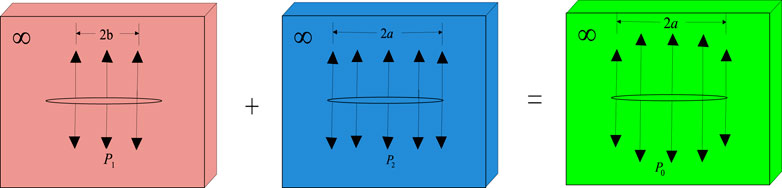
FIGURE 1. Hydraulic fracturing model.
In Figure 1, there is no stress singularity at the tip end of the crack, and the intensity factor is
when
On the basis of the aforementioned analysis, water injection pressure should be considered in case of water leaks in the fracture
Combining with the equation
4 Crack propagation mechanism of the hard roof induced by hydraulic fracturing
The crack propagation induced by hydraulic fracturing of coal and rock mass is affected by many factors, such as the stress field of surrounding rock mass and the structural and mechanical properties of coal and rock mass. Generally, the propagation direction of the hydraulic-induced cracks in coal and rock mass in the buried depth range of 200-600 m was in the same direction of the minimum horizontal stress, forming the vertical main crack (Yang et al., 2012; Wang et al., 2017). Under the continuous impact of high-pressure water, wing cracks and branch-shaped cracks are formed. In the case of relatively low permeability of coal and rock mass, high-pressure water will form a high-stress zone at the tip of the crack, which will form a dominant stress under the complex stress of the overlying strata stress, which is formed by maximum and minimum principal stresses of the coal–rock mass, gradually expanding to the deep of coal and rock mass. In this process, the water gradually penetrated into the coal and rock through the main fissure and the airfoil cleft so that the water–coal–rock contact surface increased, and the coal–rock contact surface was wetted by the large contact angle of the water body, and the water content of the coal and rock body increased gradually and then humidified the soft rock mass, thus changing the coal–rock structure, weakening the coal and rock, and improving the connection between the cracks (Shi et al., 2016b; Wu and Kang, 2017).
The high-pressure liquid generated bidirectional compressive stress
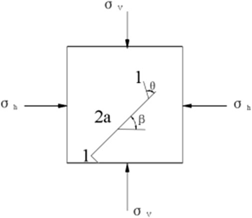
FIGURE 2. Schematic diagram of bidirectional stress on the fracture in the coal body.
Under certain conditions of coal and rock mass, the most important factor affecting hydraulic fracturing is the fracturing fluid on water pressure and dynamic damage of coal and rock mass. The external pressure fluid has direct and indirect effects on the fracture mechanics of the fracture surface of coal and rock mass. The direct action originates from the hydrodynamic pressure in the crack, and the indirect effect is derived from the tensile stress of the water on the crack structure surface. In the process of hydraulic fracturing of coal and rock mass, the main crack is formed primarily by direct actions, and the airfoil branching crack is mainly as a result of indirect actions.
5 Engineering practice of hydraulic fracturing in the roof
Along with the continuous development of coal mining methods, the control methods for hard roofs are also undergoing constant changes (Kang et al., 2017; Rashed et al., 2020). Some methods are rarely used, such as the coal pillar support method, because a large number of coal pillars are used to maintain the relative stability of the roof, resulting in low recovery of coal resources (Hua, 2004; Chang et al., 2018). The goaf filling method is also rarely used because of its high costs. The weakening method by water injection and directional hydraulic fracturing plays an important role, as shown in Table 1. Each method has corresponding applicable conditions and top-control effects. In this study, the directional hydraulic fracturing method was used to control the roof of the mining face for the actual situation of the top plate of No. 2 Well in Sihe Coal Mine.
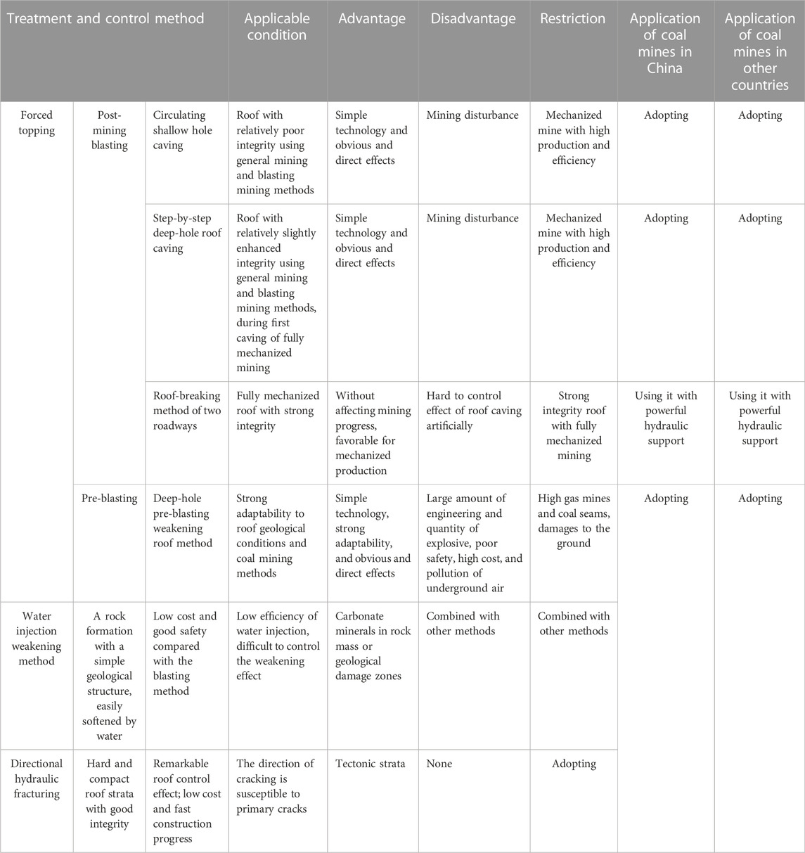
TABLE 1. Comparison of control methods for hard and difficult roof caving.
No. 2 Well of Sihe Coal Mine is located in Jincheng, Shanxi Province, in the north of central China (Figure 3). The mine is a high gas mine, and the main coal seam is No. 15. The depth of the coal seam was between 329 m and 419 m. Both the direct roof and main roof were compact and hard limestone. Most of the limestone intensity was concentrated between 110 MPa and 130 MPa with the average of 123.43 MPa, belonging to a very hard roof. The position of the mudstone interlayer in the roof was deviated. The average intensity was 45.32 MPa, the hardness of Przewalski was 8, and the shear strength was 4.74 MPa.
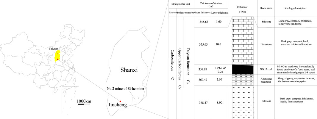
FIGURE 3. Location and stratigraphic structure of the main mining seam of No. 2 Well of Sihe Coal Mine.
5.1 Analysis of the stress test in the coal seam roof
The coal seam inclination angle was 1–8°, with the average of 4°. The coal seam thickness was 2.58 m on average. The coefficient of variation was 30%, and the recoverable index was 1. The strength, structure, and geostress field of the roof rock stratum are the basis for the design of the hard roof by the directional hydraulic fracturing technology. According to the field observation, the roof of the mining face had no false roof, and the immediate roof was limestone. The lithology included gray, animal fossil debris, calcite veins, laminated marl, and mudstone. According to the geological data, the thickness of the immediate roof rock layer was 9 m on average, the layer was compact and hard, the joint fissures were relatively developed, and the integrity and stability were good. The average uniaxial compressive strength of rock formation was 127 MPa, the average uniaxial tensile strength was 7.5 MPa, and the average shear strength was 16.2 MPa, belonging to a typical rigid roof.
The in situ strength test was carried out on the rock within 10 m of the roof rock drilling with the surrounding rock strength testing device. The uniaxial compressive intensity of the rock mass was between 80 MPa and 140 MPa. The electronic borehole peeper was used to observe the surrounding rock structure above the No. 15 coal seam roof, and it was found that there was a weak interlayer with a thickness of about 400 mm between the oblique length of 22 m and 25 m and the vertical height was 11–12.5 m. The integrity of the siltstone was also good for the deeper drilling (Figure 4). The ground stress level of No. 15 coal belonged to the low ground stress area, and the stress field was σH>σV>σh, which was dominated by tectonic stress.
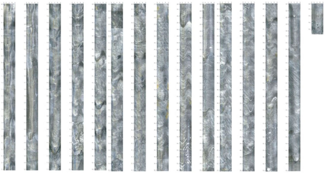
FIGURE 4. Inner wall peep map of 0–35 m borehole of the coal seam roof.
Directional hydraulic fracturing technology to control the hard roof can minimize the integrity of the roof by using high-pressure water, effectively control hard roof collapse and roof caving, as well as avoid causing safety and gas accidents during the mining of normal working face. The specific parameters of the roof surrounding rock in this mine are shown in Table 2.
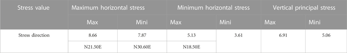
TABLE 2. Strength test parameters for surrounding of No. 15 coal roof.
5.2 Hydraulic fracturing construction parameters
Drilling was carried out using a diameter enhanced-strengthen drill with a diameter of Φ56 mm. Two types of fracturing boreholes were arranged in the cutting face, and drilling and fracturing of the fracturing borehole L′ were first performed, followed by S′ construction and fracturing operations (Figure 5). According to the analysis of the borehole view, there was a layer of No. 14 coal with a distance of 14 m from the vertical height of the No. 15 coal seam. Considering the maximum weakening of the direct roof (0–10 m) and hydraulic fracturing of rock formations between 5 m and 17 m, the drilling distance was set at 10 m, and the drilling construction parameters are shown in Table 3.
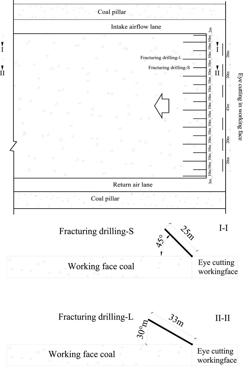
FIGURE 5. Borehole layout for hydraulic fracturing of the working face.
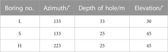
TABLE 3. Design parameters of drilling.
5.3 Hydraulic fracturing technology and process
Drill holes in the hard roof were fractured with the pillar-type hydraulic rotary drill, and a special drill was used for the hard rock. After the drilling was completed, the surrounding rock structure of the borehole was observed by the borehole peeper, and the slotting positions were determined according to the distribution of cracks. After the drilling was completed in the slotting position, the ordinary drill bit was replaced with a KZ54 special drill bit (Figure 6) to open a wedge groove with a diameter of approximately double the diameter at a designated position. The slotted section was from the hard and complete section of the roof and then was slotted again after a certain distance until the end of the 30 m drilling. After the entire drilling and grooving were completed, it was rinsed with static pressure water.
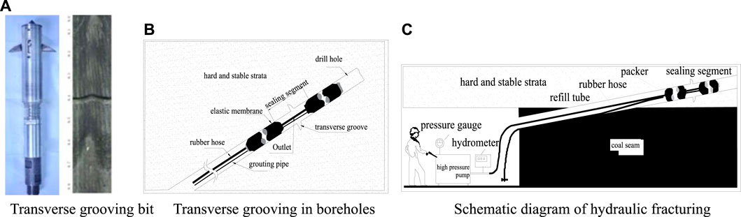
FIGURE 6. Diagram of hole sealing and construction technology of the straddle expansion packer. (A) Transverse grooving bit; (B) transverse grooving in boreholes; (C) schematic diagram of hydraulic fracturing.
After the drilling was completed, the hole sealer was connected and installed. Then, the manual pump was used to seal the sealing hole, and the sealing pressure should not be less than 10 Mpa. After sealing, the drilling hole was observed and the valve was shut off to prevent the water in the sealing device from flowing backward. Finally, a high-pressure hose and water pump were used for installation, connection, and debugging.
For the high-pressure hydraulic fracturing, an explosion-proof switch was equipped according to the motor power of the high-pressure water injection pump to run the pump. The high-pressure rubber hose and water pump outlet were close-coupled. After connecting the components, the sealing of each connection was checked. After the installation, connection, and commissioning, the water injection steel pipe was connected to push the hole packer to preset the position. The reverse fracturing method was used; that is, the fracturing was performed from the slot on the bottom of the borehole. Before fracturing, the sealing conditions of the joints were checked. The construction equipment in the fracturing process is shown in Table 4.
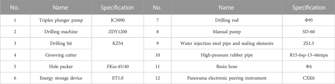
TABLE 4. Main construction equipment.
Safety measures were taken during the fracturing. It is strictly prohibited for personnel to pass before the fracturing borehole to prevent the water injection pipe from penetrating the borehole and injuring people. The high-pressure water pump supplied water first, and then it was powered. Then, it was slowly pressurized. Meanwhile, the pump pressure gauge and pressure gauge data of the manual pump were recorded. The pressurizing was continued until the cracking of prefabricated cracks. At this point, the pressure decreased sharply. The constant pressure water injection made the continuous crack extension, and meanwhile, the roof was weakened. The fracturing time was determined according to on-site fracturing conditions. It was no less than 30 min for the first three cracks, and no less than 20 min for the last few cracks. Finally, the transverse cracks were formed along the direction of the crack. In the case of water leakage from the roadway roof, coal sides, or boreholes, the fracturing shall be stopped immediately. After the fracturing is completed, the high-pressure pump shall be powered off first and then the water shall be stopped. After the return valve of the high-pressure pump was closed, the shoot-through on the water injection steel pipe shall be removed. The remaining water in the hole packer shall be discharged.
6 Hydraulic fracturing effect
By using directional hydraulic fracturing combined with long and short boreholes, the roof above the coal seam and the bonding force between the rock layers were weakened, and the strength was reduced. The effect can be directly reflected by the suspended area of the roof and the pressure of the roadway.
6.1 Hydraulic fracturing effect on working face cutting
According to the monitoring data and changing curves of the roof suspended area (Figure 7), the maximum suspended roof area during the working face mining could meet the requirement of less than 4 m × 4 m, and the effect of hydraulic fracturing is obvious.
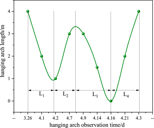
FIGURE 7. Changing curves of suspended ceiling length during fracturing.
According to the observation results of post-fracture ore pressure, the roof caved in order, the overhang areas of the goaf were effectively controlled, and the effective cutting top protected the safety of both sides of the roadway and working face. Since the implementation of this technology for more than 10 years, the blasting forced topping measures have never been used during the initial mining period, and the gas concentration in the working face and upper corner has never exceeded the upper limit set by the state. The direct roof caved in completely when the working face advanced 10–14 m during the initial mining, the roof weighting step of the main roof was 30.1 m on average, and the periodic roof weighting pace of the main roof was 16.5 on average.
6.2 Mine pressure monitoring of the working face along the roadway
It can be seen from the monitoring curves of roadway surface displacement during mining that the maximum displacement of both sides was 126 mm, the maximum displacement of the roof and floor was 50 mm, the maximum deformation of both sides of the roadway was 171 mm, and the maximum deformation of the top and bottom plates was 90 mm under the action of roadway deformation. Roadway deformation was still dominated by two-sided deformation, followed by deformation of the roof and floor, while the deformation of two sides was the main deformation before mining. The deformation of the two roadways was started at about 50 m in the advanced mining face, and the speed of deformation accelerated around 20 m ahead of the working face. In the final stage of working face mining, the deformation did not exceed 200 mm (Figures 8).
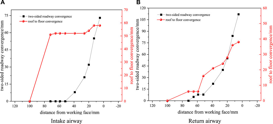
FIGURE 8. Surface displacement curves of roadway during mining. (A) Intake airway; (B) return airway.
In general, the deformation of the roadway was controlled. It shows that the hydraulic fracturing technology can effectively block the transfer of lateral abutment pressure from the working face to the roadway and coal pillar.
7 Conclusion
The use of the directional hydraulic fracturing can effectively expand the crack in the roof plate. The crack initiation and propagation pressure are mainly related to the ground stress. The extension range is affected by the positions of the borehole in the roof and the fracturing section in the borehole, as well as the degree of development of the primary cracks in the roof.
1) Based on the theoretical analysis of traditional linear elastic fracture mechanics and coal and rock mechanics, the criterion of shear fracture was determined for the formation of horizontal cracks in hydro-fractured primitive coal and rock mass or natural cracks. Hydraulic fracturing is a fracture formed by hydrodynamic fracturing water acting on the normal stress perpendicular to the fracture surface after reaching a certain pressure, which is regarded as a pure I-shaped crack problem; considering the singularity of the crack tip, the cohesive force, and, the crack of the coal rock fissure surface when the internal water leaks, the internal water pressure should meet some conditions, and the basic condition formula for the hydraulic cracking crack propagation is obtained.
2) The formation of cracks involves a vertical main crack and extended-airfoil branching cracks that interconnect transversely and longitudinally. Under the wetting effect of hydrodynamic pressure water, the stress of the coal and rock was changed and the mechanical parameters were weakened, such as the compression, tensile and elasticity modulus and etc., thus achieving the structural transformation and slight weakening of coal and rock mass. According to the bidirectional stress of coal–rock mass, the maximum principal compressive stress of crack opening was obtained. During the process of hydro-fracturing cycling in coal and rock mass, the main effect on the formation of the main fracture was direct, while the main effect on the branch fracture of airfoil was indirect.
3) This article summarized and analyzed the technology and effect of hydraulic fracturing with the hard roof in No. 2 Well of Sihe Coal Mine, which has been used for many years. It is proved that the successful application of this technology can eliminate many potential safety hazards caused by the treatment of the hard roof using the blasting method. It provides reference for other coal-producing countries to control the hard roof. However, this study did not monitor the influence range of hydraulic fracturing and the real-time change of the original rock stress of the surrounding rock during the process of hydraulic fracturing, which should be the focus of follow-up research.
Data availability statement
The datasets presented in this study can be found in online repositories. The names of the repository/repositories and accession number(s) can be found in the article/supplementary material.
Author contributions
JM: conceptualization, methodology, writing–original draft preparation, and writing–review and editing; HL: software and validation; XG, FT, and HG: investigation and visualization. All authors have read and agreed to the published version of the manuscript.
Funding
This work was financially supported by the National Natural Science Foundation of China (Grant No. 52174230), Postdoctoral Science Foundation of China (CN) (Grant No. 2021MD703848), and Fundamental Research Funds for the Central Universities (Grant No. 2020CXNL10).
Conflict of interest
The authors declare that the research was conducted in the absence of any commercial or financial relationships that could be construed as a potential conflict of interest.
Publisher’s note
All claims expressed in this article are solely those of the authors and do not necessarily represent those of their affiliated organizations, or those of the publisher, the editors, and the reviewers. Any product that may be evaluated in this article, or claim that may be made by its manufacturer, is not guaranteed or endorsed by the publisher.
References
Cai, F., and Liu, Z. G. (2016). Simulation and experimental research on upward cross-seams hydraulic fracturing in deep and low-permeability coal seam. J. China Coal Soc. 41, 113–119.
Chang, Q., Tang, W., Ying, X., and Zhou, H. (2018). Research on the width of filling body in gob-side entry retaining with high-water materials. Int. J. Min. Sci. Technol. 28, 519–524. doi:10.1016/j.ijmst.2017.12.016
Deng, G. Z., Wang, S. B., and Huang, B. X. (2004). Research on behavior character of crack development induced by hydraulic fracturing in coal-rockmass. Chin. J. Rock Mech. Eng. 23, 3489–3493.
Du, C. Z., Mao, X. B., and Bu, W. K. (2008). Analysis of fracture propagation in coal seams during hydraulic fracturing. J. Min. Saf. Eng. 25, 231–238.
Feng, Y. J., and Kang, H. P. (2013). Hydraulic fracturing initiation and propagation. Chin. J. Rock Mech. Eng., 3169–3179.
Feng, Y. J., and Kang, H. P. (2012). Test on hard and stable roof control by means of directional hydraulic fracturing in coal mine. Chin. J. Rock Mech. Eng. 31, 1148–1155.
Han, B. S. (2016). Research on fracturing mechanism of low permeability coal seam and application of surface CBM drainage. Coal Geol. Explor. 44, 25–29.
Hu, Y. Q., and Zhao, J. Z. (2000). Hydraulic re-fracturing technique for forning new fractures while blocking old fracturs. J. Southwest Petroleum Inst. 22, 61–64.
Hua, X. Z. (2004). Study on gob-side entry retaining technique with roadside packing in longwall top-coal caving technology. J. Coal Sci. Eng. china 10, 9–12.
Huang, B. X., Cheng, Q. Y., Liu, C. Y., Wei, M. T., and Fu, J. H. (2011). Hydraulic fracturing theory of coal-rock mass and its technical framework. J. Min. Saf. Eng. 28, 167–173.
Kang, H. P., and Feng, Y. J. (2012). Monitoring of stress change in coal seam caused by directional hydraulic fracturing in working face with strong roof and its evolution. J. China Coal Soc. 37, 1953–1959.
Kang, H. P., Wang, H., and Gao, F. Q. (2009). Stress distribution characteristics in rock surrounding heading face and its relationship with supporting. J. China Coal Soc. 12, 1585–1593.
Kang, J., Shen, W., Bai, J., Yan, S., Wang, X., Li, W., et al. (2017). Influence of abnormal stress under a residual bearing coal pillar on the stability of a mine entry. Int. J. Min. Sci. Technol. 27, 945–954. doi:10.1016/j.ijmst.2017.06.012
Li, S. W., and Wang, M. (2013). New technology of three-dimensional gas drainage combined hydraulic fracturing roof with high level drilling borehole. Coal Sci. Technol. 41, 79–81.
Lin, B. Q., Meng, J., Ning, J., Zhang, M. B., Li, Q. G., and Liu, Y. (2012). Research on dynamic characteristics of hydraulic fracturing in coal body containing gas. J. Min. Saf. Eng. 29, 106–110.
Liu, Y., Liu, J. L., Wen, Z. H., and Wei, J. P. (2015). Study on technology of hydraulic punching by multi-stage coal breaking for enhancing gas drainage in soft coal seams with low permeability. J. Saf. Sci. Technol. 10, 27–32.
Niu, X. Z., and Li, X. Y. (1992). High pressure water injection to the main roof as a new approach for preventing rock burst disasters in coal mines. Chin. J. Rock Mech. Eng. 11, 88–95.
Rashed, G., Mohamed, K., and Kimutis, R. (July 2020). Canonsburg, Pennsylvania, USA, Proceedings of the 39th International Conference on Ground Control in Mining.A coal Rib monitoring study in a room-and-pillar Retreat mine
Shi, X. Y., Wen, G. J., Bai, J. H., and Xu, X. J. (2016). A physical simulation experiment on fracture propagation of coal petrography in hydraulic fracturing. J. China Coal Soc. 41, 1145–1151.
Wang, H. Y., Yu, B., Xia, B. W., Gong, T., and Zhang, R. (2017). Study on propagation of hydraulic fracture in combined hard roof. China Saf. Sci. J. 27, 98–103.
Wang, P., Mao, X. B., Du, C. Z., and Sun, F. J. (2009). Study on the propagation mechanism of the crack for the borehole hydraulic fracturing in coal seam. J. Min. Saf. Eng. 26, 31–35.
Wei, J. P., Jin, Z., Yang, Y., Shi, H., and Feng, W. (2002). Numerical simulation of hard roof control. Chin. J. Rock Mech. Eng. 21, 2488–2491.
Wu, R. L., Xu, J. L., and Qin, W. (2011). Numerical simulation of gas control in fully mechanized top coal caving face with roof pre-splitting at initial mining period. J. Min. Saf. Eng. 28, 319–322.
Wu, Y. Z., and Kang, H. P. (2017). Pressure relief mechanism and experiment of directional hydraulic fracturing in reused coal pillar roadway. J. China Coal Soc. 42, 1130–1137.
Xia, B. W., Hu, K., and Lu, Y. Y. (2013). Mechanism of crack-oriented of hydraulic fracture and its technique in mine. J. Chongqing Univ. Nat. Sci. Ed. 36, 8–13.
Xu, Y. P., Lin, B. Q., Zhai, C., Li, X. Z., and Sun, X. (2011). Analysis on dynamic characteristics of cracks extension in directional hydraulic fracturing and its application. China Saf. Sci. J. 21, 104–110.
Yan, S. H., and Ning, Y. (2000). The mechanism of hydrobreakage to control hard roof and its test study. J. China Coal Soc. 25, 32–35.
Yang, J. C. (2017). Application of high pressure water pre-splitting forced caving technology in shendong mining area. Saf. Coal Mines 48, 63–68.
Yang, J. S., Wang, Y. B., Li, A. Q., Chen, Z. H., and Zou, Y. S. (2012). Experimental study on propagation mechanism of complex hydraulic fracture in coal-bed. J. China Coal Soc. 37, 73–77.
Yu, B., and Duan, H. F. (2014). Study of roof control by hydraulic fracturing in full-mechanized caving mining with high strength extra-thick coal layer. Chin. J. Rock Mech. Eng. 33, 778–785.
Keywords: coal seam roof, hydraulic fracturing, fracture, extension criterion, intensity factor
Citation: Ma J, Li H, Guo X, Tian F and Guo H (2022) A control method for hydraulic fracturing of the hard roof with long and short boreholes. Front. Mater. 9:1035815. doi: 10.3389/fmats.2022.1035815
Received: 03 September 2022; Accepted: 29 November 2022;
Published: 19 December 2022.
Edited by:
Zou Quanle, Chongqing University, ChinaReviewed by:
Zhihui Ma, Sichuan University of Science and Engineering, ChinaYongyu Wang, China University of Geosciences Wuhan, China
Copyright © 2022 Ma, Li, Guo, Tian and Guo. This is an open-access article distributed under the terms of the Creative Commons Attribution License (CC BY). The use, distribution or reproduction in other forums is permitted, provided the original author(s) and the copyright owner(s) are credited and that the original publication in this journal is cited, in accordance with accepted academic practice. No use, distribution or reproduction is permitted which does not comply with these terms.
*Correspondence: Jinkui Ma, Mjg5MDA1NTU3QHFxLmNvbQ==