 Haytham F. Isleem1*
 Daudi Salezi Augustino2
 Ahmed Salih Mohammed3
 Ahmed M. Najemalden4
 P. Jagadesh5
 Shaker Qaidi6,7
 Mohanad Muayad Sabri Sabri8
- 1Department of Construction Management, Qujing Normal University, Qujing, China
- 2Department of Structural and Construction Engineering, University of Dar es Salaam, Dar es Salaam, Tanzania
- 3College of Engineering, University of Sulaimani, Sulaymaniyah, Iraq
- 4Highways and Bridges Engineering Department, Technical College of Engineering, Duhok Polytechnic University, Duhok, Iraq
- 5Department of Civil Engineering, Coimbatore Institute of Technology, Coimbatore, India
- 6Department of Civil Engineering, College of Engineering, University of Duhok, Duhok, Iraq
- 7Department of Civil Engineering, College of Engineering, Nawroz University, Duhok, Iraq
- 8Peter the Great St. Petersburg Polytechnic University, St. Petersburg, Russia
In the present era of architecture, different cross-sectional shapes of structural concrete elements have been utilized. However, this change in shape has a significant effect on load-carrying capacity. To restore this, the use of column confinements with elliptical sections has gained attention. This paper aim to investigate the effect of elliptical shape sections of confined concrete reinforced with Carbon Fiber Reinforced Polymer (CFRP) and steel tube on axial load-carrying capacity. This study is achieved using following tools Finite Element (FE) in Abaqus and Artificial Neural Networks (ANN) modeling. The study involved a 500-mm-high column with three sets of aspect ratios: 1.0, 1.5, and 2.0. In each aspect ratio, three different layers of CFRP were used, i.e., .167, .334, and .501-mm. Analytical results showed that with the increase in aspect ratio from 1 to 2, there is a decrease in ultimate axial load of about 23.2% on average. In addition, the combined confining pressure of steel tube and CFRP increases with a decrease in dilation angle as the number of CFRP layers increases. The failure mode for the column with a large aspect ratio is local buckling at its mid-height along the minor axis. The result showed a good correlation between FE and experimental results of ultimate stress and strains, with a mean squared error of 2.27 and .001, respectively. Moreover, ANN and analytical models showed a delightful correlation of R2 of .97 for stress models and .88 for strain models, respectively. The elliptical concrete section of the column confined with steel tubes can be adopted for a new architectural type of construction; however, with more than three aspect ratios, the wrapping of the section with CFRP jackets is highly recommended.
1 Introduction
The durability of concrete has been a major concern for concrete structural elements exposed to chloride and salty environments for many years. Solution for the above problem is to pour the concrete in confining jackets, which control the exposure of concrete to an aggressive environment. Numerous studies have investigated concrete columns enclosed by different materials (Guo et al., 2009; Isleem et al., 2021) . These jackets are Poly Vinyl Chloride (PVC), Fiber Reinforced Polymer (FRP), steel tubes, and different fibers, among others. Under axial compression, the use of PVC increases the ductility of the concrete column by 1.28 to 2.35 times the unconfined equivalent concrete but the loss in confining strength of PVC when the temperature rises (Woldemariam et al., 2019). To overcome the above-stated problem, the introduction of high-strength steel tubes on behalf of PVC tubes is reported in the literature. However, when a specimen is exposed to a high corrosion environment, several researchers introduce the FRP as a wrapping element which not only increases strength but also enhances both the elastic stiffness and post-strain hardening (Zeng et al., 2021).
The introduction of FRP composites in the civil engineering sector offers numerous benefits in comparison to conventional building materials. Even engineers and researchers have observed a rise in the use of FRP composites in civil engineering applications, both in existing and retrofitted reinforced structures (Zeng et al., 2020; Abdel et al., 2022). The addition of different types of fibers to the specimen improves the concrete’s post-cracking behavior, energy absorption capacity, and toughness nature as reported in the literatures (Khan and Ali, 2016; Amin and Tayeh, 2020; Zeyad et al., 2022a; Khan and Ali, 2022). Several researchers recommend using agricultural and non-agricultural industrial waste for concrete production to improve its quality on pre-loading and post-loading behavior (Amin et al., 2021; Azevedo et al., 2022; Jagadesh et al., 2022; Saad et al., 2022). According to the literature (Elchalakani et al., 2020; Zeng et al., 2020), the use of FRP as wrapping materials for column specimens increases their load-carrying capacity and other associated properties. It can be concluded that the different types of fiber or fiber composite materials, such as FRP, that use an integral part, show no better results when compared to the use of FRP as an external wrapping material. The usage of Carbon Fiber Reinforced Polymer (CFRP) in columns will enhance the material’s ductility when subjected to lateral loads is reported by Zeng et al. (2020). A 1.0 mm CFRP layer showed a 27% increase in the axial capacity of the column compared to a column without CFRP jackets (Abdel et al., 2022).
In column specimens, the confinement effect of core concrete depends on the material strength and section size (Sun et al., 2022). The elliptical section reduces the axial capacity, leading to local buckling at the mid-height. Effects on several parameters, like longitudinal reinforcement, hoop reinforcement, slenderness ratio, and so on, also affect the load-carrying capacity of column specimens (Isleem et al., 2022a; Elchalakani et al., 2020). Studies have been conducted both numerically and experimentally on composite columns like concrete-filled PVC tubes (Isleem et al., 2022b) and concrete-filled steel tubes (He et al., 2019).
(Abadel et al., 2022) Inferred in 2022 that the use of both welded wire mesh and CFRP in retrofitting columns is cost-effective; however, the use of CFRP increases ductility as compared to welded wire jackets. This ductility in the structural column increases the column’s post-load carrying capacity after initial elastic stiffness. (Gemi et al., 2021) suggested in 2021 that the use of different wrappings such as Glass Fiber Reinforced Polymer (GFRP) composite on beams improved energy dissipation and load-carrying capacity to 394% and 237%, respectively. Using FRP wrapping on pultruded beams infilled with reinforced concrete significantly improved ductility, load capacity, and energy dissipation capacity. In 2022, (Gemi et al., 2022), observed that GFRP and CFRP increased the initial stiffness with a full wrapping effect of 44.2% and 65.4%, respectively. In structural concrete members such as beams, the introduction of an opening tremendously affects the shear capacity, which steel rebar alone cannot restore (Augustino et al., 2022a). Restoring this capacity through external strength is limited by the type of opening. The strengthening technique using CFRP increased load-carrying capacity and ductility for openings with a diameter-to-beam depth ratio (D/H) of less than 3 is reported by Aksoylu et al. (2020). From the above discussion, it can be concluded that the introduction of FRP (like CFRP, GFRP, etc.) results not only in increasing the load-carrying capacity of specimens and their associated properties like ductility, energy dissipation, and so on, but also protects the inner specimen from harmful outer agents.
The confined concrete column dilates as plasticity increases. This lateral volumetric change of strain after the composite has yielded results in high confining pressure on the confining material, which tends to advance the second linear phase of the composite (Lin et al., 2014). The axial behaviour of composite columns is influenced by the concrete strength is noted by Khan et al. (2020); Zeyad et al. (2022b). In most instances, the dilatancy of concrete decreases as its grade increases (Chung et al., 2002). In the plastic flow of concrete, the concrete-damaged plasticity utilizes materials with almost the same dilation angle throughout the confinement. This is done through a default eccentricity of .1 in Abaqus; however, a small dilation angle approaching zero indicates that the inelastic deformation is incompressible (Abaqus et al., 2004). This indicates that at high confining pressure, the dilation angle reduces.
The increase in compressive strength has less ductility compared to normal concrete, leading to less lateral expansion of concrete and a small confining pressure (Jiang et al., 2007; Augustino et al., 2022b). Regardless of whether FRP-confined concrete columns are loaded monotonically or cyclically, the stress-strain curve envelopes follow the same trend (Ozbakkaloglu and Akin, 2012). This trend indicates that the effectiveness of confining FRP jackets depends on the strength of individual jackets and the thickness of layers. CFRP jackets in the industry can provide the safety level of the elliptical section on its local buckling as the aspect ratio increases. The usage of steel tubes not only results in higher load-bearing capacity of columns, but the introduction of CFRP as a wrapping element on steel tubes leads to further increase in the load-bearing capacity of composite columns. Several experimental and numerical modeling studies (Liu et al., 2017; Cai et al., 2019) have been conducted on the behavior of elliptical concrete-filled steel tubes and reported that the influence of elliptical shape on load carrying capacity of column. Elchalakani et al. (2020) tested 15 solid, circular, GFRP-reinforced concrete columns and reported an increase in ductility for both axial and eccentric loading conditions.
Composite tubes like concrete-filled steel tubes and steel-embedded concrete specimens have increased usage in civil construction applications due to their auspicious performance resulting from the composite action between the individual components (Isleem et al., 2022a). Different geometrical sections provide typical features that bring many advantages and disadvantages, enabling columns to be oriented to carry the external load most efficiently (Lam and Testo, 2008). To provide structural engineers with viable options, the effect on the elliptical cross-sections of various parameters such as confined concrete strength, tube thickness, aspect ratio, etc. was investigated in this study.
Most experimental tests use resources, which necessitated the use of an artificial intelligence algorithm to predict parameters. However, caution is required, such as data partitioning, training, and testing to avoid the overfitting/underfitting of results (Matlab, 2004; Althoey et al., 2022). A comparison of experimental with analytical studies to ensure the quality of analytical results has been reported by (Khan et al., 2021) in 2021. To reduce the cost of experimental work, the time required to experiment, and the manpower involved with it, researchers are pushed to conduct analytical studies (Khan and Ali, 2020). In recent days, researchers have recommended analytical methods to understand the behavior (load-carrying capacity, ultimate strain, etc.,) of composite members (Khan and Ali, 2020b). The experimental setup of the confined concrete column using steel tube and CFRP is too demanding and requires more resources to be deployed. The use of finite element (FE), analytical, and ANN modeling could be an alternative approach to the experimental investigation of these composites.
1.1 Novelty of research
In literature, the effect of aspect ratio on concrete-filled steel columns is limited. Even though several works discuss the effect of aspect ratio on the different types of column specimens (steel columns, concrete columns, and concrete columns wrapped in FRP) with different geometrical natures (circular, rectangular, and square). However, according to the knowledge of the authors, there is no FEM simulation related to the CFRP-wrapped, confined concrete-filled steel columns with elliptical cross sections. Hence, in this study, the effect of aspect ratio on the CFRP-wrapped confined concrete-filled steel columns with elliptical cross-section is investigated using FE analysis, and ANN modeling is investigated with the help of existing experimental results from the literature.
2 Methodology
2.1 Finite element modeling (FEM)
2.1.1 Material properties and interface modeling
The FEM was developed using Abaqus software with inputs from experimental results (Zheng et al., 2021). The column had a height of 500 mm with variable cross-sections (2a × 2 b) of 194 × 194, 230 × 154, and 252 × 126 mm, representing an aspect ratio of 1.0, 1.5, and 2.0, respectively. Aspect ratios 1, 1.5, and 2.0 were designated by letters A, B, and C, followed by numbers 1, 2, and 3, referring to the number of CFRP layers used. The layers of CFRP were attached to the steel tube using tie constraints. The steel tube confined inside the concrete is the modelled in ABAQUS tool as a tie constraint Figure 1. For all of these constraints, the steel tube was set as the master surface due to its high strength compared to the strength of the concrete and CFRP.
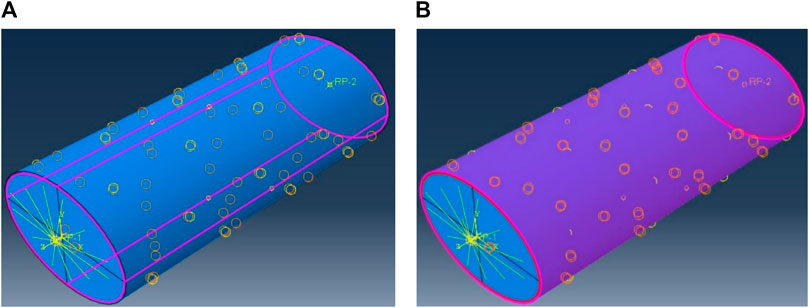
FIGURE 1. Tie constraints used assembling concrete, steel tube, and CFRP; (A) between concrete and steel tube, and (B) between steel tube and CFRP.
An extra repeated model was run in each set of CFRP layers and labeled with Romanic numbers, I and II. Since steel tubes are ductile, their plastic failure was established based on their yield strength. Concrete was modeled with compressive strength, Young’s modulus, and peak strain of 32 MPa, 24.8 GPa, and .0022, respectively. These parameters were used to establish the post-behavior of concrete using stress-inelastic crushing and cracking strains curves, as shown in Eq. 2.1 and Eq. 2.2. The behavior of the steel tube exhibited a bilinear stress-strain curve; an example from existing models is provided in Figure 2A. The incremental compressive stress can be calculated using the expression provided in Figure 2C, in which the stress at the elastic stage is considered to be 50% of the standard cylinder compressive strength. Figure 2B provides a mathematical equation to generate the tensile stress train response of unconfined concrete; however, the failure of concrete was controlled as CFRP failed.
Where
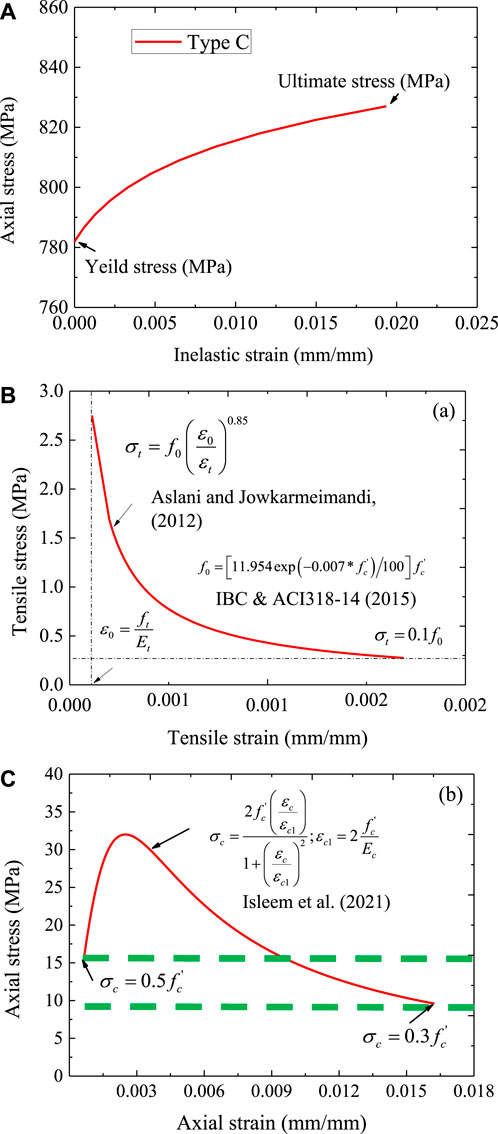
FIGURE 2. Stress-strain curves; (A) Inelastic strain and stress response of steel tube, (B) Tensile behaviour of concrete, and (C) Compressive behaviour of concrete.
In these equations,
In the concrete model, the dilation angles were varied, and the effect of confining pressure was assessed as shown in Figure 3, in which eccentricity, viscosity, a ratio of biaxial and uniaxial compressive stress, and K were maintained as default values (3DS, 2011; Tao and Chen, 2015). The CFRP had thicknesses of .167, .334, and .501 mm, with engineering constants shown in Table 1. The details of the column specimens and parameters used in modeling are shown in Tables 2, 3.
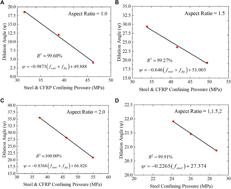
FIGURE 3. Effect of aspect ratio and confining pressure on dilation angle; (A) Aspect ratio of 1.0, (B) Aspect ratio of 1.5, (C) Aspect ratio of 2.0 and (D) Aspect ratio of 1.0,1.5 and 2.0.

TABLE 1. Mechanical properties of CFRP (Zhang et al., 2022; Jiang et al., 2014).
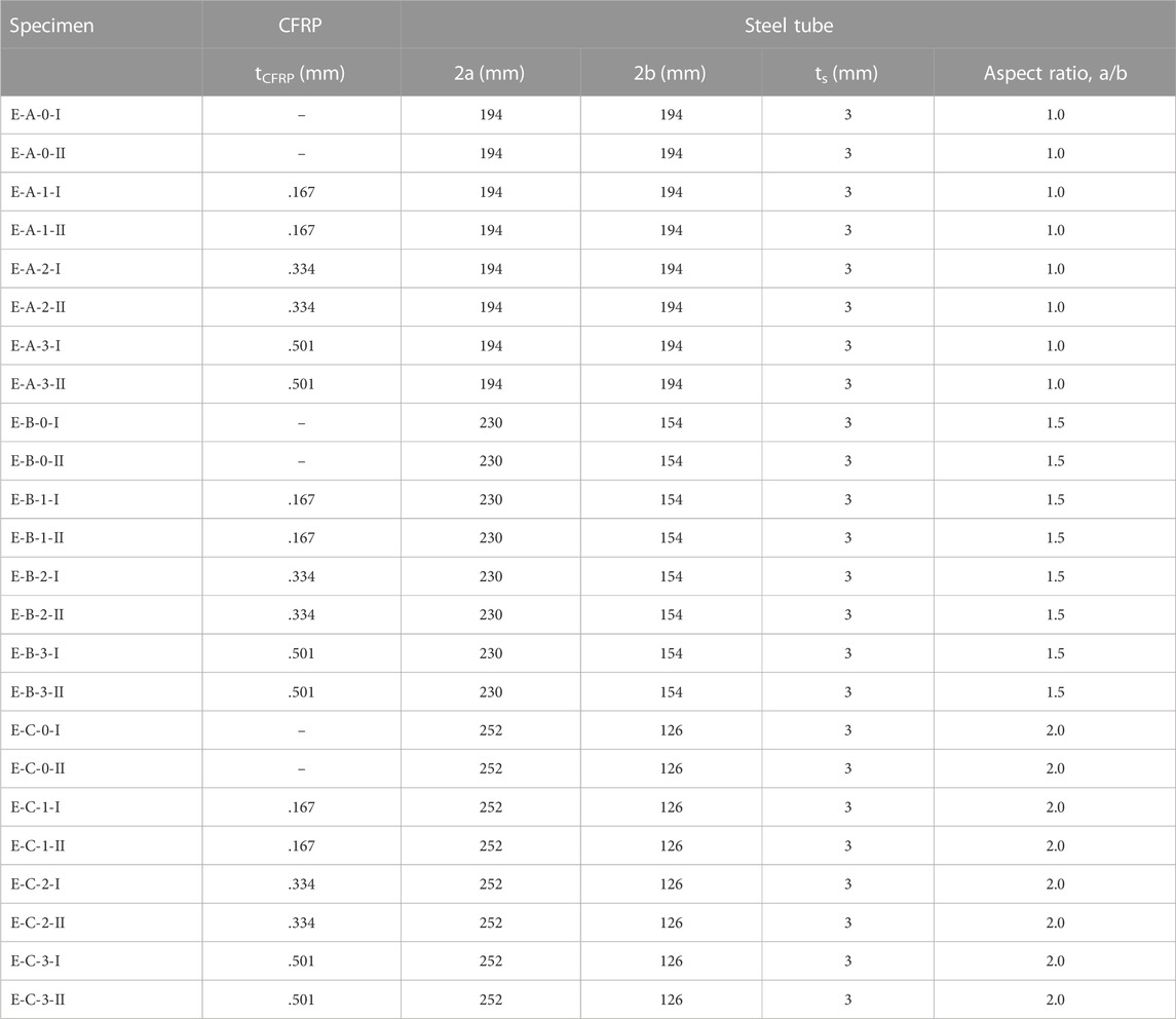
TABLE 2. Geometry of steel tube and CFRP [Zhang et al., 2022].
TABLE 3. Material properties of concrete, steel tubes, and CFRP used in modeling.
2.1.2 Loading and boundary conditions
The column was loaded axially, necessitating the boundary condition. To maintain homogeneity of the composite specimens during loading, steel tube, CFRP, and concrete were coupled using kinematic coupling at the top and bottom to the created reference points in ABAQUS. All displacements and rotation degrees of freedom for the composite specimens were displaced by this coupling. At reference points, the axial displacement and axial load were prescribed and extracted in ABAQUS as shown in Figure 4. Since the column becomes more fragile as its aspect increases, the E-C, E-B, and E-A columns were assigned displacements of 0.04 H, 0.03 H, and 0.02 H, respectively.
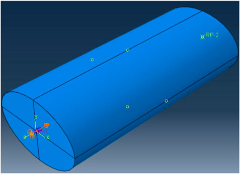
FIGURE 4. Reference points and prescribed displacement.
2.1.3 Analysis, finite element type, and meshing
Abaqus/Explicit was used in the analysis step. This was because of some advantages of this solver: it has a stable time increment and saves the storage capacity of computers as it does not permit iterations. It uses the stable known result or parameter from the previous step and generates the next output through a central difference integration scheme (3DS, 2011). This integration scheme utilizes very small time increments, resulting in a long computation time. To limit this, mass scaling was introduced at the beginning of the analysis step at a factor of 10. The Abaqus/Explicit is normally used to model the dynamic problem; however, step smoothing was used to minimize the velocity in the model, hence low kinetic energy. The kinetic energy of the whole model (ALLKE) was 5% of the total internal energy of the whole model (ALLIE), as recommended for static analysis (3DS, 2011). During discretization of modeling in ABAQUS, steel tubes and CFRP were assigned four nodes-shell elements (SC4R) with homogeneous and composite characteristics. Concrete was modeled using a solid, homogenous element called the hexagon (C3D8R). All elements had the same mesh size of 25 mm, with any variations being avoided since the small mesh sizes control the time increment in ABAQUS. Figure 5 shows the mesh of concrete, steel tube, and CFRP with their respective finite elements.
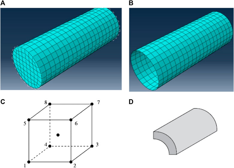
FIGURE 5. Meshing and finite elements used in modelling; (A) Structural mesh of concrete, (B) Structured mesh of steel tube and CFRP, (C) C3D8R element, the single integration point and (D) 3 mm shell element (SC4R): Note: These figures are from Abaqus (2014).
3 Results and discussion
3.1 Failure modes and behavior of confined concrete
Figures 6, 7 depict the strain variation in the column without and with CFRP, respectively. The results show that the tensile strain decreases in the steel tube as the aspect ratio increases. The variation in compressive strains and stresses in confined concrete is also affected by the aspect ratio; however, with an aspect ratio of 1, the variations are evenly distributed. This is associated with a slender section as the aspect ratio increases to 3. At an aspect ratio of 2, the shorter dimension (major axis) of the elliptical section contracted significantly, resulting in lateral concrete budging. This results in high axial compressive stress in the minor axis of the section, leading to high confining pressure. As the aspect ratio went to 3, there was uneven strain variation in the shorter diameter of the section, leading to an abrupt reduction in axial stresses, resulting in local buckling of the column in that minor axis. This phenomenon has been reported in the literature (Zeng et al., 2021).
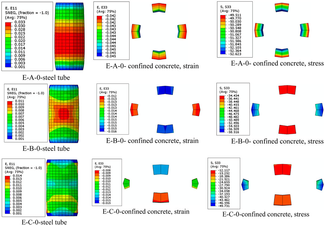
FIGURE 6. Strain variation in the column without CFRP.
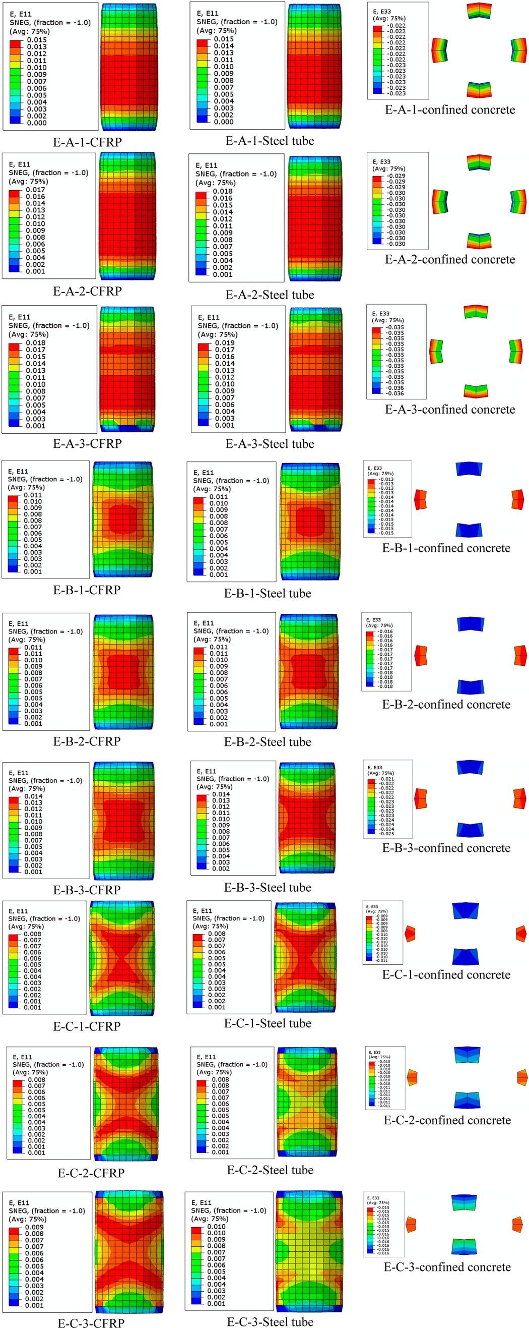
FIGURE 7. (Continued).
When a layer of CFRP was tied along the steel tube, there was a sharing of axial strains; however, for two and three layers of CFRP, the material failed slightly before compared to the specimen with steel tube alone. In general, the addition of CFRP layers delays the early failure of the elliptical section, hence improving the load-carrying capacity of the column. Concrete failure in the confinement was controlled by the failure criteria of the stress-strain curves of CFRP wraps. In elliptical sections as the number of CFRP layers and aspect ratio increased, both the steel tube and the CFRP layer failed at the mid-height of the column with a well developed of failure shape as X structure. Specimens with the high aspect ratio of 3, also with CFRP layers as two and three, and the steel tube showing no hoop strains at mid- height of the column indicate that the hoop stress is mainly carried by CFRP. This typically denotes the rupture mechanism of CFRP in a steel tube. Compared to E-C columns, the x-shaped columns for aspect ratio 2 (E-B columns) showed high strain re-distribution stress in steel tubes from the center, resulting in high axial stress in concrete.
Figures 8, 9 show the results of hoop stress in variation columns without and with CFRP, respectively. In comparison to E-B-0 and E-C-0, the E-A-0 column had high hoop tensile stress in the steel tube below the mid-height, resulting in high compressive stresses at the base. The E-B-0 showed homogeneity in the budging of the specimen at mid-height compared to the E-C-0, which showed less stress at mid-height, indicating less capability of withstanding loads. In addition, the use of a combined steel tube and CFRP layer showed high hoop strain and stress, denoting high confining pressure with less axial deformation of concrete compared to the column with only steel tubes. This composite plays a virtual role in reducing the buckling of the columns with elliptical sections.
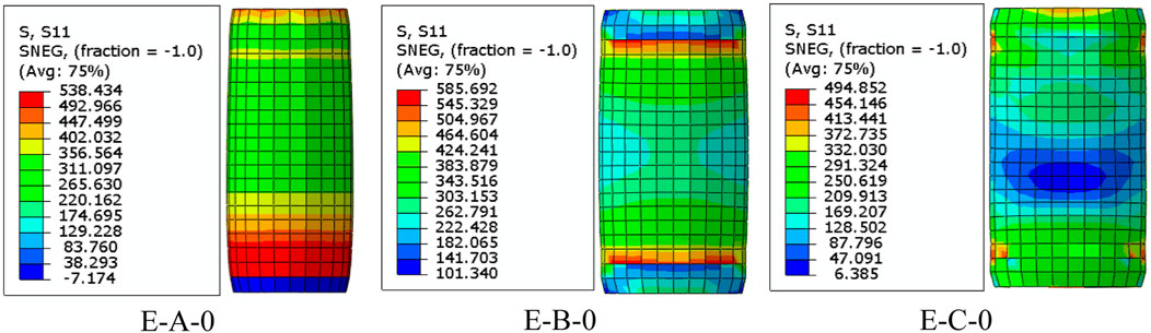
FIGURE 8. Hoop stress variation in columns without CFRP along the steel tubes.
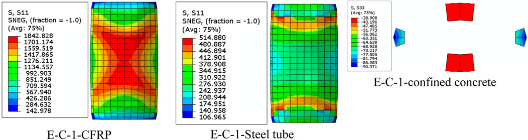
FIGURE 9. Hoop stress variation in columns with CFRP, E-C-1; along the CFRP, steel tube, and in concrete.
3.2 The confining effect of Carbon Fibre Reinforced Polymer on ultimateaxial loads
Figures 10–12 show the load-strain curves for columns with aspect ratios of 1, 1.5, and 2, respectively. The confined concrete column, E-A-0, had high axial loads of 2588 N compared to E-B-0 and E-C-0, with axial loads of 2311 and 1987 N, respectively. The axial load decreases as the aspect ratio increases. This might have been associated with the confinement efficiency being reduced as the column sections became more elliptical, i.e., aspect ratios of 2 and 3. A similar decrease in axial loads was observed by Zeng et al. (2021) in 2021 and Chen et al. (2021) also in 2021. Columns without CFRP with an aspect ratio of 3 (E-C-0) reduced the axial load to 23.2% of column E-A-0. The results also show that axial loads increased as the number of CFRP layers increased due to the increased ductility of the specimen before ultimate failure. Columns E-A-1, E-A-2, and E-A-3 had an axial load of 3006.8, 3609.1, and 4331 N, being 16.2, 39.4, and 67.3% higher than columns without CFRP (E-A-0). Columns E-B-1, E-B-2, and E-B-3 had an axial load of 2684.4, 2978.3, and 3402.7 N being 15.9, 28.8, and 47.2% high than columns without CFRP (E-B-0). In addition, columns E-C-1, E-C-2, and E-C-3 had an axial load of 3006.8, 3609.1, and 4331 N, being 16.2, 39.4, and 67.3% higher than columns without CFRP (E-C-0). These results are in agreement with the test result by Zeng et al., in 2022, where the loads of the columns are the same as the FE result. The addition of CFRP increased the post-behavior of the majority of fiber-reinforced structural elements, particularly deep concrete beams, and confined concrete [10]. This result in high ultimate loads due to strain hardening and ductility as fiber layers increased, leading to bilinear load-strain curves (Abdel et al., 2022; Lin et al., 2004) of specimens. At the second linear part of the load-strain curve, composite with CFRP layers, concrete behaved plastically, with the majority of load transfer occurring via reinforcing composites.
FIGURE 10. Load-strain curve for columns with aspect ratio 1; (A) No CFRP layer, (B) One layer, (C) Two layers, and (D) Three layers.
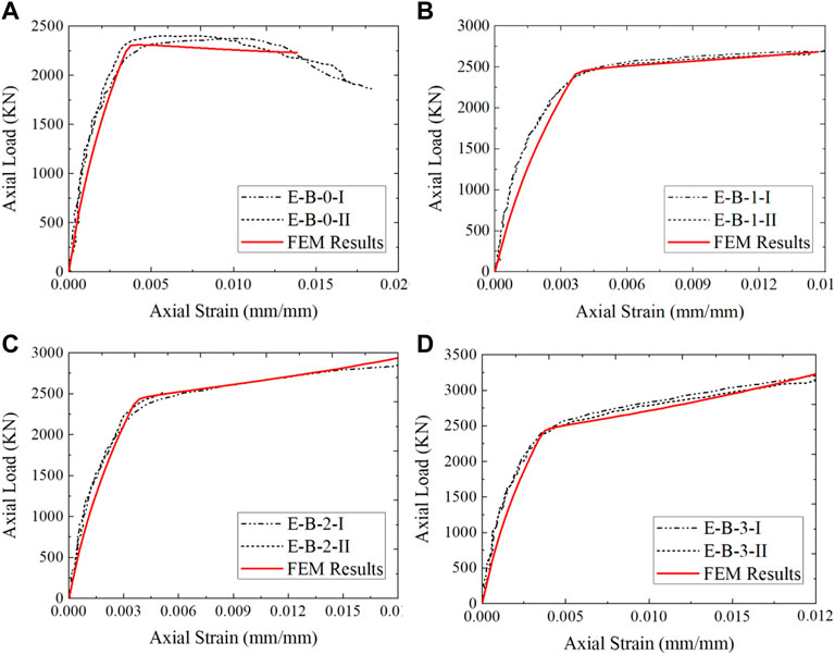
FIGURE 11. Load-strain curve for columns with aspect ratio 1.5; (A) No CFRP layer, (B) One layer, (C) Two layers, and (D) Three layers.
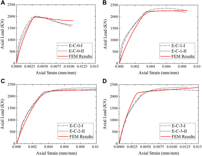
FIGURE 12. Load-strain curve for columns with aspect ratio 2; (A) No CFRP layer, (B) One layer, (C) Two layers, and (D) Three layers.
3.3 Correlation of FEM and experimental results
Figure 13 depicts the statistical assessment of FEM and experimental strain and stress results using mean square error. The results show a good correlation of mean squared error (MSE) of .001 and 2.27 for strains and stress, respectively, with a maximum strain for the composite of .025. The results also show a strong correlation between the ultimate axial load for steel-tubed columns and multiple CFRP layers. For columns with only steel tubes, the ultimate axial load appeared to be slightly different; however, the yield loads had a strong correlation with steel specimen. This is because as concrete dilates, localized failure of the column with steel tube alone occurs due to less confining pressure.
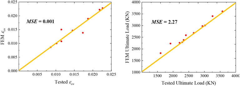
FIGURE 13. Statistical assessment of FEM and experimental results.
3.4 Artificial neural network (ANN) technique
3.4.1 Model formulation
The ANN technique is widely used for many purposes, such as classification, pattern recognition, and modeling. In particular, the use of ANN for predicting the compressive strength and strain of FRP-confined concrete has been studied (i.e., Cascardi et al., 2017). However, the use of ANN for CFRP-confined concrete columns with elliptical cross-sections has not yet been explored. Therefore, the aim of this is to use the ANN toolbox provided in MATLAB (MATLAB, 2012) to estimate the axial compressive stress and strain capacities of confined concrete that exhibit hardening behavior as the number of CFRP increases. The number of experimental and FEM data used to train and test the ANN model was 24 in total. In the development processes of the ANN model, an appropriate selection of the input variables is a very important process. The axial load capacity of CFRP-confined structures depends on the geometric dimensions (i.e., elliptical dimension of column, thickness of steel tube, layers of CFRP) and the properties of the confining material (i.e., CFRP and steel tube). As a result, the input variables, which appear to have significant effects on the axial load capacity and strain, were taken into account with the following factors: 1)
The output variables were: 1) y1 is the ultimate stress of the ratio of composite-to-compressive strength of concrete as in Eq. 3.4, and 2) y2 is the ratio of ultimate strain-to-strain of concrete for the confined concrete column loaded with axial compression loads, as shown in Eq. 3.5:
The database was randomly divided into training (60%), validation (20%), and testing (20%). Choosing the appropriate number of hidden neurons and the number of hidden layers is a major parameter in obtaining an accurate ANN model. The number of hidden layers and the number of nodes in hidden layers are usually determined via trial-and-error procedures or using suggested rules (Amani and Moeini, 2012). Therefore, one layer of hidden nodes was based on previous suggestions (Isleem et al., 2022b), and the optimum model parameters (i.e., the number of hidden nodes and the rate of learning) were found by a proposed training approach. This can be accomplished using one of several available approaches, in which the network was trained with a set of random values for the initial weight, hidden node number, and learning rate. The Levenberg–Marquardt denoted by Trainlm (Demuth and Beale, 1998) was selected as the training function. The performance function is MSE, and the transfer functions in both hidden and output layers are Purelin transfer functions. It is to be noted that the default transfer functions in the ANN toolbox are Tansig (Demuth and Beale, 1998). By transforming the data in the first and last ANN layers using the function (Eqs 3.6 and Eq. 3.7) and choosing Purelin transfer functions, the ANN model reveals an acceptable performance:
Once the ANN model is built and the first and last data layers are chosen and normalized, the network can now be trained. The performance of the system on the test data is used to measure the success of the learning process. These test data are usually not involved in the training process; rather, they are used in determining the generalization capability of the trained network, which ensures that the trained data are not memorized during the learning process (Awolusi et al., 2019). On the other hand, the validation data set is used to evaluate the performance of trained data in each epoch sequentially. Based on the overall model performance and the least mean square error achieved across a wide range of training parameters, the optimal number of hidden nodes was found to be three, and the optimal number of iterations (epochs) in performing the training was found to be four. Using these resulting parameters in a training approach, the most accurate results can then be obtained. Figure 14 clearly shows the result of R2 for the train, validate, and test data, which have the best correlation of test data, indicating the best training has been achieved. The performance and accuracy of trained data were assessed using the mean square error. Figure 15 shows that the data in training, validation, and testing had a close mean square error. In Eqs 3.8–3.15, the predictions from the ANN model in practical form were generated, in which the inputs (x) and outputs (y) were scaled using the minimum and maximum values provided in Table 4, w is the order of weight for hidden and output neurons,
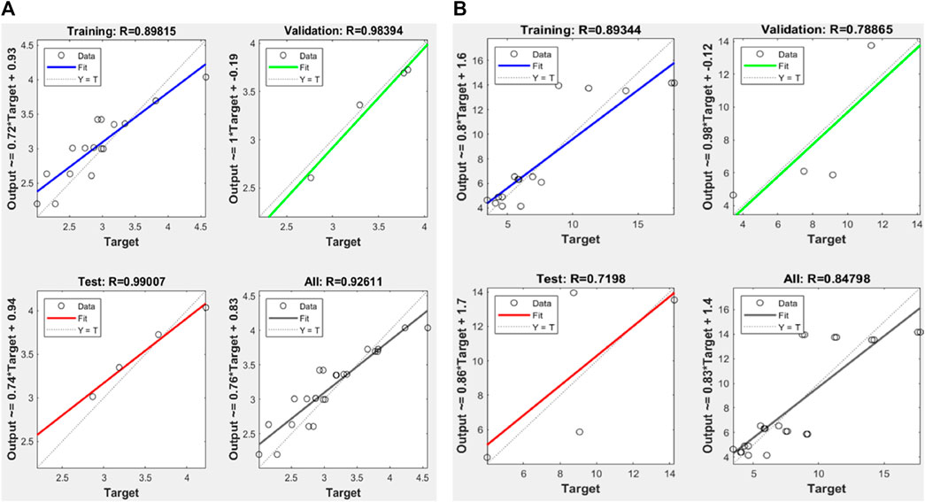
FIGURE 14. Performance of trained data in ANN; (A) stress ratios and (B) strain ratios.
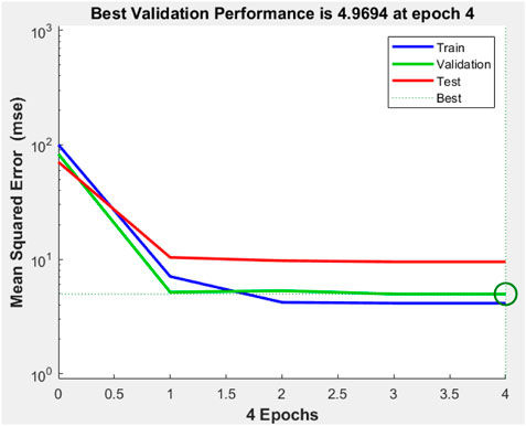
FIGURE 15. Mean squared error for trained data.
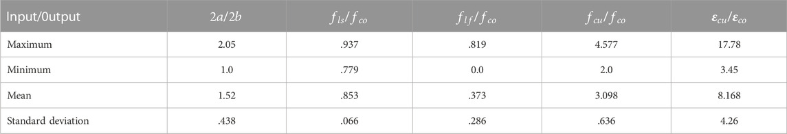
TABLE 4. The scale of input data.
3.5 Analytical axial stress and strain models
The analytical models were developed based on the ratio of minor and major dimensions of the elliptical section, 2a, and 2b, respectively, and the factor to account for the effect of the combined confinement by a steel tube and CFRP against the strength of confining concrete, fco. The total confined pressure due to the steel tube and CFRP is given in Eq. 3.8.
where
Where
Where,
The evaluation of the analytical stress ratio and strain ratio was based on regression analysis. The values were compared to experimental ratios. There was a strong correlation between the experiment and the analytical results, with an R2 of .9657 for the stress ratio and .8755 for the strain ratio in Figure 16. This relationship shows that the sum of the square of the differences between the point and the regression line is small, leading to the least mean square error as in ANN. The t-test was also conducted to assess the difference in mean values between experimental and analytical stress ratios and strain ratios, considering unequal variances. The t-values were .006 for stress ratios and .06 for strain ratios, both of which were less than the t-critical of 1.68. These results indicate no statistical differences between experimental and analytical ratios (Ross, 2004).
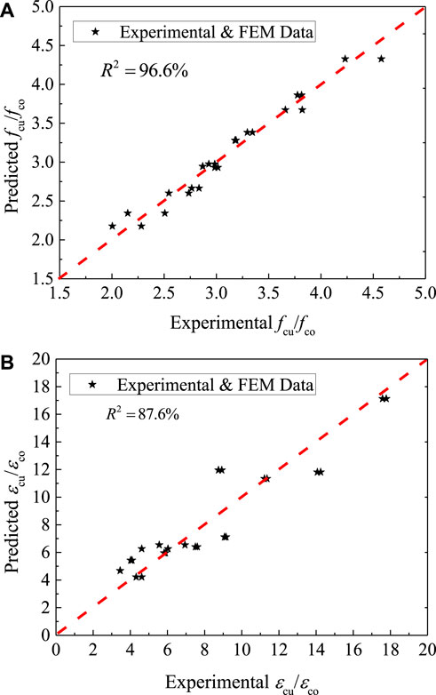
FIGURE 16. The performance of the analytical model against experimental data; (A) stress ratios and (B) strain ratios.
4 Conclusions and recommendation
The following conclusions were drawn in this study.
• The axial load-carrying capacity is affected as the column becomes more elliptical. A high aspect ratio of 3 results in local buckling of the mid-height with a lower axial compression load of 1987 N. With the increase in the aspect ratio of the column section, the CFRP was highly stressed, with a well-developed x-shape of stress variation at the mid-height of the column. This indicates the possibility of CFRP rupture in the minor axis of the cross-section with a relatively high axial load of the column 67.3% for a column specimen of aspect ratio as 3, with CFRP versus the same column without CFRP.
• The increase in the number of layers of CFRP resulted in bilinear load-strain curves. The second linear part of the load-strain curve is due to the high confinement pressure contributed by CFRP resulting from the dilation of concrete in its plastic stage. The combined effect of steel tube and CFRP results in high confining pressure, leading to a small dilation angle. This indicates the plastic flow of the concrete was high, resulting in high confining pressure and an increased axial load-strain ratio.
• The artificial neural network and analytical model developed predict stress and strain ratios well. ANN had R2 values of .926 and .848. These compared well with analytical R2 values of .966 and .876 for stress and strain ratios, respectively.
On the point of application, these composite columns are used for architectural purposes and also applications where the specimens with a high eccentrically load. For the same specimen conditions, this research can be further extended to the eccentrical loading conditions, with higher concrete strength, different slenderness ratios, and different types of FRP. This kind of future research will solve structural engineers’ analysis problems. Xie et al., 2021.
Data availability statement
The original contributions presented in the study are included in the article/Supplementary material, further inquiries can be directed to the corresponding author.
Author contributions
Conceptualization: HI, Investigation: HI, DA, and PJ, Methodology: HI and DA, Project administration: HI and DA, Resources: HI, DA, and MS, Software: HI and DA, Supervision: HI, Validation: DA and PJ, Visualization DA, SQ, AN, AM, and PJ, Writing—Original draft: DA and PJ, Writing—review and editing: DA, SQ, AN, AM, and PJ, Funding: MS, AM, and AN.
Funding
The authors acknowledge that the research is partially funded by the Ministry of Science and Higher Education of the Russian Federation as part of the “World Class Research Center Program: Advanced Digital Technologies” (Contract No. 075-15-2022-311 dated 20.04.2022).
Acknowledgments
The Structural Concrete Lab was made possible by Qujing Normal University, Qujing, Yunnan, China.
Conflict of interest
The authors declare that the research was conducted in the absence of any commercial or financial relationships that could be construed as a potential conflict of interest.
Publisher’s note
All claims expressed in this article are solely those of the authors and do not necessarily represent those of their affiliated organizations, or those of the publisher, the editors and the reviewers. Any product that may be evaluated in this article, or claim that may be made by its manufacturer, is not guaranteed or endorsed by the publisher.
References
3DS, 2011 3Ds, (2011). Abaqus 6.11 theory manual. Providence, RI, USA”: Dassault Systèmes Simulia Corp.
Abadel, A. A., Masmoudi, R., and Iqbal Khan, M. (2022). Axial behavior of square and circular concrete columns confined with CFRP sheets under elevated temperatures: Comparison with welded-wire mesh steel confinement. Structures 45, 126–144. doi:10.1016/J.ISTRUC.2022.09.026
Abaqus, (2014). Analysis USER’S guide volume V: Prescribed conditions. CONSTRAINTS Interact. https://www.academia.edu/28334906/Abaqus_Analysis_Users_Guide.
Abdel, A. A., Khan, M. I., and Masmoudi, en R. (2022). Experimental and numerical study of compressive behavior of axially loaded circular ultra-high-performance concrete-filled tube columns. Case Stud. Constr. Mat. 17, 01376. doi:10.1016/J.CSCM.2022.E01376
Aksoylu, C., Yazman, Ş., Özkılıç, Y. O., Gemi, L., and Arslan, M. H. (2020). Experimental analysis of reinforced concrete shear deficient beams with circular web openings strengthened by CFRP composite. Compos. Struct. 249, 112561. doi:10.1016/j.compstruct.2020.112561
Althoey, F., Akhter, M. N., Nagra, Z. S., Awan, H. H., Alanazi, F., Khan, M. A., et al. (2022). Prediction models for marshall mix parameters using bio-inspired genetic programming and deep machine learning approaches: A comparative study. Case Stud. Constr. Mat. 18, 01774. doi:10.1016/j.cscm.2022.e01774
Amani, J., and Moeini, R. (2012). Prediction of shear strength of reinforced concrete beams using adaptive neuro-fuzzy inference system and artificial neural network. Sci. Iran. 19 (2), 242–248. doi:10.1016/j.scient.2012.02.009
Amin, A., and Tayeh, B. A. (2020). Investigating the mechanical and microstructure properties of fiber reinforced lightweight concrete under elevated temperatures. case Stud. Constr. Build. Mater. 13, 00459. doi:10.1016/j.cscm.2020.e00459
Amin, A., Zeyad, A. M., Tayeh, B. A., and Agwa, I. S. (2021). Effects of nano cotton stalk and palm leaf ashes on ultrahigh performance concrete properties incorporating recycled concrete aggregates. Constr. Build. Mater. 302, 124196. doi:10.1016/j.conbuildmat.2021.124196
Astm, (2008). Standard test method for tensile properties of polymer matrix composite materials. West Conshohocken: D3039/D3039M-08.
Augustino, D. S., Kabubo, C., Kanali, C., and Ocharo, R. (2022a). The orientation effect of opening and internal strengthening on shear performance of deep concrete beam using recycled tyre steel fibres. Results Eng. 15, 100561. doi:10.1016/j.rineng.2022.100561
Augustino, D. S., Onchiri, R. O., Kabubo, C., and Kanali, C. (2022b). Mechanical and durability performance of high-strength concrete with waste tyre steel fibres. Adv. Civ. Eng. 32. 4691972, doi:10.1155/2022/4691972
Awolusi, T. F., Oke, O. L., Akinkurolere, O. O., Sojobi, A. O., and Aluko, O. G. (2019). Performance comparison of neural network training algorithms in the modeling properties of steel fiber reinforced concrete. Heliyon 5 (1), 01115. doi:10.1016/j.heliyon.2018.e01115
Azevedo, A. R. G., Amin, M., Hadzima-Nyarko, M., Agwa, I. S., Zeyad, A. M., Tayeh, B. A., et al. (2022). Possibilities for the application of agro-industrial wastes in cementitious materials: A brief review of the Brazilian perspective. Clean. Mater. 3, 100040. doi:10.1016/j.clema.2021.100040
Cai, Y., Quach, W-M., and Young, B. (2019). Experimental and numerical investigation of concrete-filled hot-finished and cold-formed steel elliptical tubular stub columns. Thin-Walled Struct. 145, 106437. doi:10.1016/j.tws.2019.106437
Cascardi, A., Micelli, F., and Aiello, M. A. (2017). An Artificial Neural Networks model for the prediction of the compressive strength of FRP-confined concrete circular columns. Eng. Struct. 140, 199–208. doi:10.1016/J.ENGSTRUCT.2017.02.047
Chen, G., Wang, Y., Yu, T., Wan, B., Zhang, B., and Liu, en Q. (2021). Behavior and design-oriented model for elliptical FRP-confined concrete under axial compression. Eng. Struct. 249, 113387. doi:10.1016/j.engstruct.2021.113387
Chung, H., Yang, K., Lee, Y., and Eun, H. (2002). Stress–strain curve of laterally confined concrete. Eng. Struct. 24, 1153–1163. doi:10.1016/s0141-0296(02)00049-4
Demuth, H., and Beale, M. (1998). Neural network toolbox for use with matlab. User’s guide. Natick, MA, USA: The MathWorks, Inc.
Elchalakani, M., Dong, M., Karrech, A., Mohamed Ali, M. S., and Huo, J-S. (2020). Circular concrete columns and beams reinforced with GFRP bars and spirals under axial, eccentric, and flexural loading. J. Compos Constr. 24, 04020008. doi:10.1061/(asce)cc.1943-5614.0001008
Gemi, L., Madenci, E., and Özkılıç, Y. O. (2021). Experimental, analytical and numerical investigation of pultruded GFRP composite beams infilled with hybrid FRP reinforced concrete. Eng. Struct. 244, 112790. doi:10.1016/J.ENGSTRUCT.2021.112790
Gemi, L., Madenci, E., Özkılıç, Y. O., Yazman, Ş., and Safonov, A. (2022). Effect of fiber wrapping on bending behavior of reinforced concrete filled pultruded GFRP composite hybrid beams. Polym. (Basel) 14 (18), 3740. doi:10.3390/polym14183740
Guo, Y., Huang, P., Yang, Y., and Li, L. (2009). Experimental studies on axially loaded concrete columns confined by different materials. KEM 402, 513–518. doi:10.4028/www.scientific.net/KEM.400-402.513
He, L., Lin, S., and Jiang, H. (2019). Confinement effect of concrete – filled steel tube columns with infill concrete of different strength grades. Front. Mater. 6. doi:10.3389/fmats.2019.00071
Isleem, H. F., Jagadesh, P., Ahmad, J., Qaidi, S., Althoey, F., Najm, H. M., et al. (2022b). Finite element and theoretical investigations on PVC-CFRP confined concrete columns under axial compression. Front. Mater. 9, 1055397. doi:10.3389/fmats.2022.1055397
Isleem, H. F., Peng, F., and Tayeh, B. A. (2022a). Confinement model for LRS FRP-confined concrete using conventional regression and artificial neural network techniques. Compos. Struct. 279, 114779. doi:10.1016/J.COMPSTRUCT.2021.114779
Isleem., H. F., Muhammad, A., Wesam, S. A., Shah., M. K., Zeb., S., Ali Musarat., M., et al. (2021). Axial compressive strength models of eccentrically-loaded rectangular reinforced concrete columns confined with FRP. Mater. (Basel) 14 (13), 3498. doi:10.3390/ma14133498
Jagadesh, P., Nagarajan, V., Karthik Prabhu, T., and Arunachalam, K., “Effect of nano-titanium dioxide on mechanical properties of fly ash and ground granular blast furnace slag based geopolymer concrete” Journal of building engineering, Vol.61, 105235, 2022. doi:10.1016/j.jobe.2022.105235
Jiang, S. F., Ma, S. L., and Wu, Z. Q. (2014). Experimental study and theoretical analysis on slender concrete-filled CFRP-PVC tubular columns. Constr. Build. Mat. 53, 475–487. doi:10.1016/j.conbuildmat.2013.11.089
Jiang, T., and Teng, J. G. (2007). Analysis-oriented stress–strain models for FRP – confined concrete. Eng. Struct. 29, 2968–2986. doi:10.1016/j.engstruct.2007.01.010
Khan, M., and Ali, M. (2020). Cracking behaviour and constitutive modelling of hybrid fibre reinforced concrete. J. Build. Eng. 30, 101272. doi:10.1016/j/jobe.2020.101272
Khan, M., and Ali, M. (2016). Use of glass and nylon fibers in concrete for controlling early age micro cracking in bridge decks. Constr. Build. Mater. 125, 800–808. doi:10.1016/j.conbuildmat.2016.08.111
Khan, M., Ali, M., and Xie, C. (2022). Effectiveness of hybrid steel basalt fiber reinforced concrete under compression. case Stud. Constr. Mater. 16, 00941. doi:10.1016/j.cscm.2022.e00941
Khan, M., Cao, M., and Ali, M. (2020). Cracking behaviour and constitutive modelling of hybrid fibre reinforced concrete. J. Build. Eng. 30, 101272. doi:10.1016/J.JOBE.2020.101272
Khan, M., Cao, M., Chaopeng, X., and Ali, M. (2021). Experimental and analytical study of hybrid fiber reinforced concrete prepared with basalt fiber under high temperature. Fire Mater. 46 (1), 205–226. doi:10.1002/fam.2968
Lam, D., and Testo, N. (2008). “Structural design of concrete filled steel elliptical hollow sections,” in Composite construction VI Colorado USA.
Lin, H. J., and Liao, C. I. (2004). Compressive strength of reinforced concrete column confined by composite material. Compos. Struct. 65 (2), 239–250. doi:10.1016/j.compstruct.2003.11.001
Liu, F., Wang, Y., and Chan, T-M. (2017). Behaviour of concrete-filled cold-formed elliptical hollow sections with varying aspect ratios. Thin-Walled Struct 110, 47–61. doi:10.1016/j.tws.2016.10.013
Ozbakkaloglu, T., and Akin, E. (2012). Behavior of FRP-confined normal- and high-strength concrete under cyclic axial compression. J. Compos. Constr. 16 (4), 451–463. doi:10.1061/(asce)cc.1943-5614.0000273
Ross, S. M. (2004). Introduction to probability and statistics for engineers and scientists. Third edit. Berkeley: Elsevier Academic Press.
Saad, M., Agwa, I. S., Abdelsalam, B., and Amin, M. (2022). Improving the brittle behavior of high strength concrete using banana and palm leaf sheath fibers. Mech. Adv. Mater. Struct. 29 (4), 564–573. doi:10.1080/15376494.2020.1780352
Sun, Z., Zou, Y., Wang, C., Pan, J., Wang, L., and Chen, M. (2022). Study on confinement mechanism of core concrete in steel tubular-corrugated steel plate confined concrete columns. J. Build. Eng. 52, 104497. doi:10.1016/j.jobe.2022.104497
Tao, Y., and Chen, J. F. (2015). Concrete damage plasticity model for modeling FRP-to-concrete bond behavior. J. Compos. Constr. 19 (1), 04014026. doi:10.1061/(asce)cc.1943-5614.0000482
Wang, Z., Wang, D., Smith, S. T., and Lu, en D. (2012). CFRP-confined square RC columns. I: Experimental investigation. J. Compos. Constr. 16 (2), 150–160. doi:10.1061/(asce)cc.1943-5614.0000245
Woldemariam, A. M., Oyawa, W. O., and Nyomboi, T. (2019). Structural performance of uPVC confined concrete equivalent cylinders under axial compression loads. Buildings 9 (4), 82. doi:10.3390/buildings9040082
Xie, C., Cao, M., Khan, M., Yin, H., and Guan, J. (2021). Review on different testing methods and factors affecting fracture properties of fiber reinforced cementitious composites. Constr. Build. Mater. 273, 121766. doi:10.1016/j.conbuildmat.2020.121766
Zeng, J. J., Da Liang, S., Li, Y. L., Guo, Y. C., and Shan, G. Y. (2021). Compressive behavior of FRP-confined elliptical concrete-filled high-strength steel tube columns. Compos. Struct. 266 (100), 113808. doi:10.1016/j.compstruct.2021.113808
Zeyad, A. M., Hakeem, I. Y., Amin, M., Tayeh, B. A., and Agwa, I. S. (2022a). Effect of aggregate and fibre types on ultra-high-performance concrete designed for radiation shielding. J. Build. Eng. 58, 104960. doi:10.1016/J.JOBE.2022.104960
Keywords: carbon fibre reinforced polymer, composite column, finite elemt analysis, machine learning, elliptical sections
Citation: Isleem HF, Augustino DS, Mohammed AS, Najemalden AM, Jagadesh P, Qaidi S and Sabri MMS (2023) Finite element, analytical, artificial neural network models for carbon fibre reinforced polymer confined concrete filled steel columns with elliptical cross sections. Front. Mater. 9:1115394. doi: 10.3389/fmats.2022.1115394
Received: 03 December 2022; Accepted: 29 December 2022;
Published: 18 January 2023.
Edited by:
Mehran Khan, Hong Kong Polytechnic University, Hong Kong SAR, ChinaReviewed by:
Aref A. Abadel, College of Engineering, King Saud University, Saudi ArabiaLokman Gemi, Necmettin Erbakan University, Türkiye
Ibrahim Saad Agwa, Suez University, Egypt
Copyright © 2023 Isleem, Augustino, Mohammed, Najemalden, Jagadesh, Qaidi and Sabri. This is an open-access article distributed under the terms of the Creative Commons Attribution License (CC BY). The use, distribution or reproduction in other forums is permitted, provided the original author(s) and the copyright owner(s) are credited and that the original publication in this journal is cited, in accordance with accepted academic practice. No use, distribution or reproduction is permitted which does not comply with these terms.
*Correspondence: Haytham F. Isleem, aXNsZWVtaGF5dGhhbTg4QGdtYWlsLmNvbQ==