 Ying Wei
 Peiqing La1*
- 1State Key Laboratory of Advanced Processing and Recycling of Nonferrous Metals, Lanzhou University of Technology, Lanzhou, China
- 2Department of Automotive Engineering and Transportation, Lanzhou Vocational Technical College, Lanzhou, China
The key to the new generation of solar thermal power plants is to increase the operating temperature of molten salt to 800°C, and change the heat transfer medium from nitric acid mixed salt to chlorine mixed salt, so as to significantly reduce the cost of power generation. Therefore, the alloy material’s resistance to high temperatures and fusible chloride salt is one of the core technologies for the successful implementation of concentrated solar power (CSP) technology. In this study, the aluminum-forming alloy (AFA) 310S for the heat storage tank was prepared by the aluminum-thermal reaction casting method. The hot corrosion behavior and mechanism of AFA 310S in chloride molten salt at 800°C were studied by static immersion etching for 600 h. AFA 310S exhibits good thermal corrosion properties in KCl 20.4 wt% + MgCl2-55.1 wt% + NaCl 24.5 wt%. The results indicate that compared with commercial 310S, AFA 310S has better oxidation resistance at 800°C. At the initial stage of corrosion, dense Cr2O3 and continuous Al2O3 passivation films are formed. At the same time, MgO-rich oxidation products were produced in the outermost layers of the two alloys during the 600 h process. Over time, however, the damage caused by chlorine became more apparent, mainly due to the “oxidation-chlorination” process of the metal. A large number of cavities and cracks on the surface are formed, and the oxide layer has obvious spalling. When the Al element was added into the alloy, the dense passivation film could be formed after 120 h of corrosion with the stronger corrosion resistance. The experiment simulated the corrosion behavior in the worst environment, such as air, unoxidized alloy, molten salt without corrosion inhibitor, etc. By weight loss calculation, commercial 310S plate is completely unsuitable for CSP plant. The corrosion rates of the two alloys are compared as follows: commercial 310S > AFA 310S. To sum up, AFA 310S has a good application prospect in concentrated solar power.
Introduction
Concentrated solar power (CSP) plants need to adopt high corrosion resistance and low cost materials for heat absorbers, storage tank, of molten salt, and heat pipes as key components. As the heat storage and transfer medium of the next generation CSP in the future, chloride salt has many advantages, for instance, low price, specific heat and density, low viscosity, high thermal stability, good heat transfer and heat storage capacity, in spite of the true strong corrosion of metal materials. Alloy materials such as tanks, pipes, and valves will produce hot corrosion and high temperature oxidation reactions in a high temperature environment, which means they cannot reach the expected life of 30 years. Therefore, compatibility between molten salts and materials must be evaluated and understood in order to determine compatible materials and corrosion inhibitor methods (Wang et al., 2019; Pooja et al., 2021; Sarvghad et al., 2018; Ding et al., 2018; Sun et al., 2018a; Sun et al., 2018b; Gomez-Vidal et al., 2017a; Wang et al., 2017).
In the past 2 decades, the United States, Spain, Germany, China, India, and other countries have set foot in this area. Many researchers focus on the corrosion behavior of stainless steel and nickel-based alloys. For example, Wang et al. (2019) conducted an immersion experiment on three austenitic stainless steels 310S, 316L, and 321 in nitrate. After 42 days of immersion, 310S showed the best corrosion resistance, and the corrosion rates of 310S, 316L, and 321 are 0.499 μm/y, 1.460 μm/y, and 1.895 μm/y. There were obvious Cr depletion zones in 316L and 321, leading to intergranular corrosion (Wang et al., 2019). Similarly, Sah et al. (2018) found that 310S was significantly ennobled in carbonate melt as compared to 316L and 304. Corrosion resistance has increased with increasing Cr and Ni content in the substrate. Moreover, Gomez-Vidal et al. (2017a) studied the salt chloride corrosion properties of aluminum-containing Inconel 702, Haynes 224, and Kanthal APMT super alloys after pre-oxidation. The results were optimistic. Due to the cost reduction requirements of the next generation CSP, the operating temperature aims to increase from 565°C to 800°C, and chloride molten salt has been planned to replace nitrate as a heat storage and transfer medium (Ding and Bauer, 2021). The cost of nickel alloy is higher than that of stainless steel, so austenitic stainless steels are popular engineering materials in 700–800°C salt chloride.
The major challenge is that alloys are corroded in high temperature molten salt. Initially, commercial 300 series stainless steel had no longer good corrosion resistance in 700-800°C chloride salt according to the literature. The reason was that the chromium oxide protective film was not stable in salt chloride (Pooja et al., 2021; Gomez-Vidal and Tirawat, 2016). Next, although the traditional 310S had made some progress, the intrinsic embrittlement at room temperature due to the crystal structure of Fe-Al intermetallic had not been well solved. After that, Sarvghad et al. (2018) stated that alloys in molten chloride salt had been mainly corroded by grain boundary erosion. Protective films composed of components such as chromium oxide tend to dissolve in salt mixtures over time. Once this oxide film had holes, the alloy matrix had been corroded directly. In the environment containing Cl-, the formation of HCl and Cl2 gas accelerated the corrosion and continued to destroy the stability of the oxide film (Liu et al., 2014).
Researchers’ discussions also focused on the corrosion mechanism, so no systematic theory had been formed. Primarily, Wang et al. (2017) discussed the corrosion mechanism as a process of oxidation and chlorination. In the experiment, GH4033 formed a dense, stable oxide layer with high contents of Ti and Al, which inhibited the corrosion process. In addition, intergranular corrosion and pitting have been very common in the chloride molten salt environment. Gomez-Vidal and Tirawat (2016) believed that the depletion of Cr on the grain boundary was the key corrosion mechanism of the high Chromium alloy in molten salt. Moreover, they have discussed corrosion mechanisms of chromia-forming-alloys in molten chlorides owing to the formation of non-protective precipitates of Cr2O3 (Gomez-Vidal et al., 2017b). Similarly, Sun et al. (2018b) studied 316 and seven kinds of Ni-based alloys. The result appeared that all alloys had undergone selective dissolution of Cr, obviously leading to the formation of subsurface voids. Furthermore, temperature has been a very important factor as well. Many researchers have reported the same view that the corrosion of the alloy has increased as the temperature rises (Liu et al., 2014; Gomez-Vidal and Tirawat, 2016; Sun et al., 2018b). For example, in Gomez-Vidal et al.’s (2017a) findings, when the corrosion temperature went up from 650 to 700°C, the corrosion rate of SS310 had doubled at just 50°C, from 6.42 mm/y to 12.45 mm/y. Last but most importantly, an impurity-driven corrosion mechanism has been put forward to explain (Ding and Bauer, 2021; Ding et al., 2018). Impurity in the environment has been a significant factor, especially the oxygen. In the presence of oxygen, oxides dissolved in molten chloride salts released the oxygen component and reported the oxidation process to continue (Gomez-Vidal and Tirawat, 2016). Equally, Raiman and Lee (2018) believed that salt purity had been the most important factor affecting corrosion rate. Ding and Bauer (2020) emphasized that oxygen, water, and other substances had generated MgOHCI impurities, which would lead to serious corrosion, due to impure MgOH+ salt reacting with Cr and Si in the alloy (Ding and Bauer, 2021). Most of the chloride salt had included MgCl2 with high water absorbability, so MgOHCI impurities had existed and acted during the corrosion period.
For solving these problems, researchers tried to improve the properties of alloys, and a variety of methods have been stated, like forming protective layers, thermal spraying, dip coating, pre-oxidation (Sheng et al., 2021), adding nanoparticles to molten salt (Grosu et al., 2018), high aluminum alloy, etc. One method has been to form a protective layer on the surface of structural materials, which helps to reduce the corrosion rate (Grosu et al., 2018). Nishikata (1991) pointed out that high corrosion resistance of alloys had been achieved by forming a protective metal oxide film on the surface. Then, the United States, Germany, Japan, and other countries had explored the possibility of adding 2 %–10% aluminum to 300 series austenitic heat-resistant steel for improving its mechanical, corrosion resistance and oxidation resistance properties. In recent years, Chinese laboratories have also developed 304, 316, 310, and HP40 with the highest aluminum content of 5 wt% (Liu, 2008; Liu, 2012; La et al., 2013; La et al., 2014; Xue et al., 2015; Meng, 2016; Sheng et al., 2022). And La et al. (2012) carried out some studies on high aluminum stainless steel. As a result, 2 wt% to 4 wt% Al element had been added to 310S, and a passivation film had formed on the substrate surface that could significantly improve the high temperature oxidation resistance and mechanical properties. It has been proved that increasing Al content has benefited alloys. The composition of the oxide film on the surface of austenitic stainless steel and heat resistant steel has changed from chromium to alumina oxide, with a higher content of aluminum and a more dense structure. Because in a high temperature environment, protective alumina formation refers to establishing a continuous α-Al2O3 scale, which has been more stable than chromium oxide protective film. In fact, Al has been a great substitute for Cr, not only seeking cost reduction, but also achieving the same corrosion resistance (Liu, 2008; Liu, 2012; La et al., 2013; La et al., 2014; Xue et al., 2015; Meng, 2016; Sheng et al., 2022; Xue et al., 2015). The similar findings like Fe-Cr-Al alloy, which had been tested by Ding and Bauer, in particular, high-aluminum alloy showed excellent salt chloride resistance (Ding and Bauer, 2021). Likewise, corrosion resistance mechanism has been the formation of alumina film. Furthermore, Chen et al. (2020) have experimentally explored Fe-Cr-Al alloy as well. As known, this super alloy had good high-temperature resistance and oxidation resistance, which mainly relied on a protective oxide film of Al2O3 and Cr2O3 on the matrix. In general, the formation of a protective layer on the surface of structural materials has helped to reduce the corrosion rate (Grosu et al., 2018).
For CSP applications, currently a large number of literature on nitrate and fluoride purification methods had been published; a new chlorine purification technology had been tested. Most of the purification methods were physical purification, which had mainly been used to remove moisture and controlled the hydroxide and oxide impurities of air pollution, such as thermal purification method (Ding and Bauer, 2021). Similarly, Fernandez (2020) argued that heat treatment was important; not only for mitigation measures, but also because standard procedures must be developed (Ding and Bauer, 2021). For reducing corrosive impurities in molten salt, especially in MgCl2, the method of purification treatment mode has been tested according to the vapor pressure curve of magnesium chloride hydrate (Fernández and Cabeza, 2020a). Fernandez et al. (2020) suggested removing the hydrate in magnesium chloride by the heat treatment method (Fernández and Cabeza, 2020b).
Materials and Methods
Material
For 310S stainless steel, a medium-frequency induction furnace and a vacuum electric arc furnace were used to smelt the alloy structure by the thermite reaction method. 1.5% aluminum was added, and high-temperature molten salt corrosion resistant alloy materials were prepared by thermite method. Thermal-aluminization is a method to obtain high melting point metals by using the reducibility of aluminum. Detailed information about experimental treatments could be found in other literature (Sheng et al., 2021). High purity Fe2O3, Al, Cr, Ni, Mn, Si, C, and Ti powders were selected first, and the raw materials were weighed according to the ratio. Then the planetary grinding was carried out. The materials after ball grinding were pressed into blocks and put into a high pressure reaction kettle together with an ignition agent and filled with argon gas. Relying on the large amount of heat released by the reaction, the displaced metal melts were fused together, cooled with the furnace, and finally the aluminum thermite cast steel was obtained. Then, a vacuum induction furnace was used to melt the alloy material, which was resistant to high temperature molten salt corrosion. The alloy samples prepared by the thermite method were cut into pieces and put into the crucible. The molten cast sample was prepared in a vacuum induction furnace. Next, the alloy samples were linearly cut into 12 × 12 × 3 mm cubes. Before the test, all metal samples were ground and polished with sand paper with particle sizes of 120, 240, 600, 800, 1,200, 1,500, and 2000, respectively, cleaned with distilled water, ethanol, and acetone for 10 min, and finally dried. Sample size and weight were measured by vernier calipers, electronic balance, and then the samples were put into the drying box. The chloride molten salt was dried to remove impurities and stored in a vacuum furnace at 120 °C for later use. Before the test, Al2O3 crucible, 316SS crucible, and pot cover were cleaned with deionized water, ethanol, and acetone, and then dried at 120°C for 24 h to remove residual moisture. Table 1 shows the chemical composition of the two alloys to be tested.

TABLE 1. Chemical composition of test alloys (wt%)
The molten salt was the eutectic mixture of 20.4 wt% KCl +55.1 wt% MgCl2 + 24.5 wt% NaCl, produced by Sinopharm Chemical Reagent Company, Purity >99.5 wt%. And the heat treatment purification of the molten salt process, which was studied by Fernandez et al. (2020), was to place the three salts in a vacuum drying oven and heat them according to the following steps: at 117°C for 2 h then at 145°C for 4 h, 190°C for 4 h, 227°C for 4 h, 300°C for 4 h, 450°C for 4 h, and 600°C for 1 h, then weigh and mix the three salts in proportion, The salt purified by heat treatment was kept in a vacuum drying oven at 120°C until the experiment began (Fernández and Cabeza, 2020b). The above treatment process was designed to reduce the influence of molten salt magazines.
Static Corrosion Experiment
A high temperature muffle furnace and a vacuum drying oven were used to carry out corrosion experiments in a high temperature molten salt environment. The experimental environment was simulated under the worst conditions; no inert atmosphere was used; the surface of the alloy sample was not pre-oxidized; and only the molten salt was pre-purified by heat treatment. Static soaking experiment was carried out for 600 h at 800 °C and in air. The metal sample was completely immersed in molten salt in an alumina crucible. The gas in contact with the molten salt was air. The muffle furnace was heated from room temperature at a rate of 5°C/min, and the timing was not started until it was heated to 800°C, and the corrosion lasted for 600 h at this temperature. After the experiment, the Muffle furnace was cooled to room temperature; part of the sample was taken out to calculate the corrosion rate and placed in distilled water at 60°C for cleaning. Firstly, the loose corrosion products on the surface were removed by mechanical means, and the surface salt and the oxide layer were removed by brush and sandpaper. Secondly, the weight loss method was used to weigh, and the precision was controlled at 0.001. Finally, the corrosion rate was calculated.
Average weight changes and associated errors were calculated according to ASTM G1-03 for the mass loss method (ASTM, 2003). Cleaning methods for corroded products follow ASTM G1-03. The corrosion rate (CR) could be calculated as follows:
where K is constant 8.76×10⁷ (μm/y); W is the mass loss of the sample during the corrosion test (g); A is the sample area (cm2); T is the exposure time of corrosion test (h); D is the sample density (g/cm3).
The other part of the sample was used for characterization and observing the microstructure of the alloy.
Analysis Equipment and Methods
The surface and cross section images of the samples were observed by scanning electron microscope (SEM, JSM-6700F). Electron probe microanalysis (EPMA) was used to analyze the element distribution of the samples. The precipitates of the samples were characterized by energy dispersive X-ray spectroscopy (EDS) and X-ray diffraction (XRD) analysis and other characterization methods; they analyzed the sample structure surface and cross-section morphology, structure type and composition, analyzed the microstructure, and clarified the influencing factors of the formation mechanism. The corrosion resistance of high temperature molten salt alloy material was characterized by a static immerse experiment and weight loss analysis, and the corrosion resistance mechanism of this material was revealed.
Results
The Microstructure of AFA 310S
Figure 1 shows the microstructure of AFA 310S formed by casting aluminum smelting. The typical as-cast dendrite structure is formed by solidification, which consists of a gray γ austenitic matrix and black M23C6 type carbide precipitates at the dendritic boundary. The eutectic carbide is distributed in the austenite matrix as a skeleton. In Figure 1B, Fe is the main element of AFA 310S, and Ni, Al, Mn, and Si decrease sequentially. The precise content is shown in Table 1.
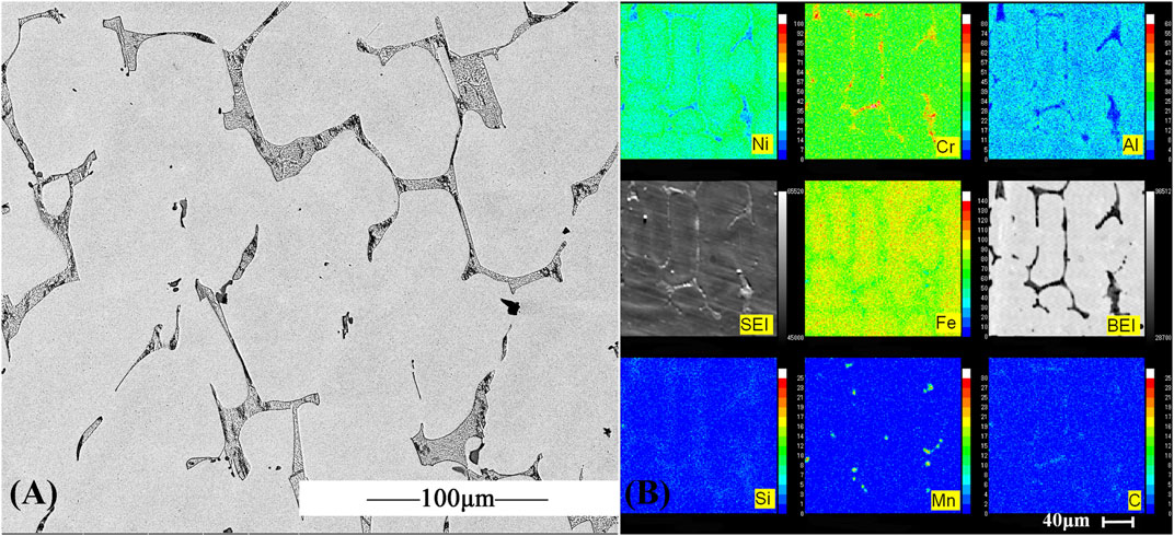
FIGURE 1. As-cast microstructure of AFA 310S after melting: (A) SEM image, (B) EPMA image.
The Mass Loss of Two Alloys
The corrosion rates of the two alloys are shown in Figure 2. It can be inferred that the corrosion rates of AFA 310S were generally lower than those of commercial 310S specimens when the sample was immersed in molten salt for 600 h at 800°C. This might be due to the different content of Al. From Table 1, Al content of AFA 310S can reach 2.64 wt%, while the data of commercial 310S is even less than 0.01wt%. As shown in Figure 2, the corrosion rate of commercial 310S reached its peak at 120 h and then declined rapidly. The difference is that the corrosion rate of AFA 310S fluctuates relatively gently, reaching its top value at 240 h and then decreasing slowly, until it drops to 7,662.69 (μm/y) at 600 h. This is basically the same as the data shown in Table 3, Ref.11. It is worth mentioning that the environment of this work is to simulate the actual worst working conditions, and the data in the literature is mostly from inert gas or experimental conditions below 700°C. In contrast to the results of this paper, the average corrosion rate of AFA 310S in molten chloride salt at 800°C after 600 h is 7662.69 μm/y (in Figure 2), in contrast to the corrosion rate of 310 in the literature at 700°C after 500 h is 12451 μm/y (in Table 2, Ref.11). The experimental environment used in this paper (at 800 °C in air) is worse than that in the literature (below 700°C, in inert gas). As a result, it is obviously proved that AFA 310S in this work has excellent resistance to high temperature molten salt.
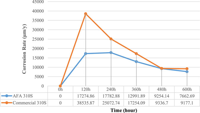
FIGURE 2. Corrosion rates versus time for two alloys in molten chloride salt at 800°C in air.

TABLE 2. Corrosion rates of several stainless steels have been reported in the literature
Analysis of Corrosion Products on the Outer Surface
Figure 3 shows the XRD results of the surface oxide layer of the two samples after 600 h of high temperature corrosion at 800°C. It can be seen that in the 600 h corrosion process, the surface products of the two samples are mainly MgO, while some manganese oxide just like, Mn3O4, MgNiO2, Mg0.9Mn0.1O, Fe+2Cr2O4, MnCr2O4 and Mg2Si2O6 are generated. Due to direct contact with molten salt, these products have formed relatively high temperature resistant oxidation product forms, and there are also KCl and NaCl residues.
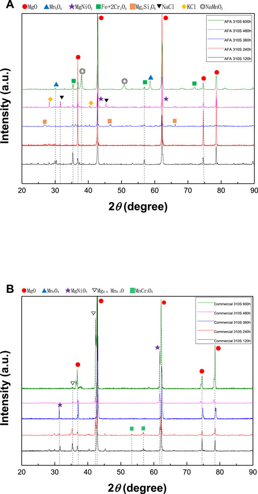
FIGURE 3. XRD results in molten chloride salt at 800 °C: (A) surface of AFA 310S in 120, 240, 360, 480, and 600 h, (B) surface of commercial 310S in 120, 240, 360, 480, and 600 h.
Morphology and Composition Analysis of the Two alloys
Figure 4A shows the SEM images of morphology on the surface of AFA 310S after corrosion for 120, 240, 360, 480, and 600 h, respectively. At different times, there is uneven oxidation produced on the surface, in company with both a spinel structure of oxide generated in blue circles and cracks in yellow rectangular boxes. Over time, though, the surface morphology appears to follow a trend from coarse to smooth and back to coarse again, which is associated with the different components of oxidation products.
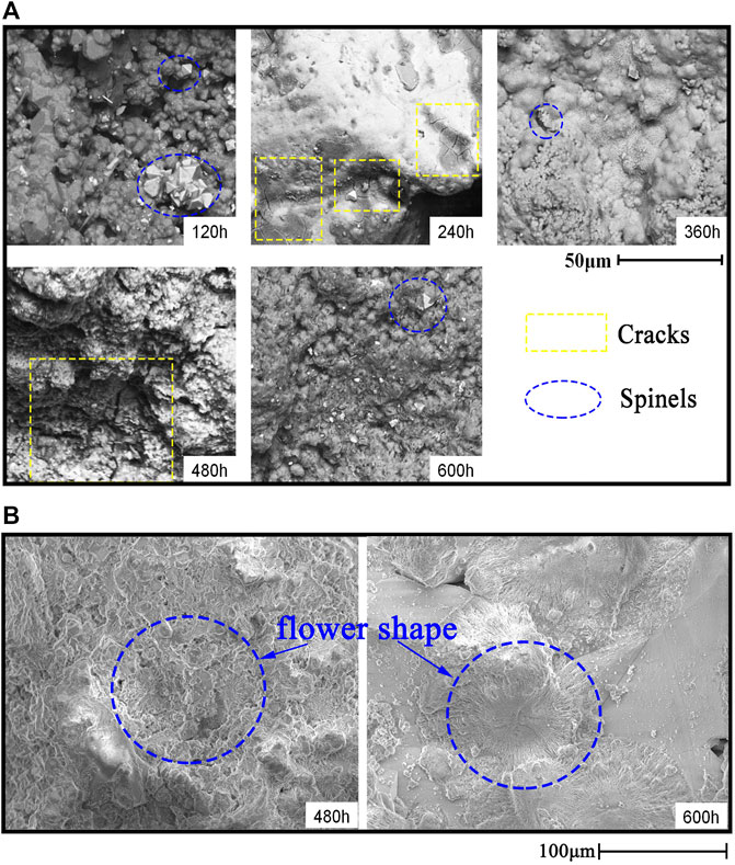
FIGURE 4. Surface morphology after corrosion at 800 °C: (A) AFA 310S, (B) commercial 310S.
By contrast, the morphology of commercial 310S appears different from AFA 310S. In Figure 4B, a flower-shaped oxide appears on the surface when exposed to 480 and 600 h in blue circles. On the grounds of XRD results, the flower-shaped oxide mainly consists of MgO, with a small amount of Cl, Ni, and Mn left, without Fe or Cr elements. In addition, some cavities exist on the surface in yellow rectangular boxes. Generally speaking, the surface morphology becomes rougher over time.
Comparison Analysis of Two alloys
As can be seen from Figure 5A, after 120 h of corrosion, a dense and continuous oxidation film of Cr2O3 and Al2O3 has been formed on the surface of AFA 310S, which has a stronger protective effect on the material matrix. The outermost oxidation film is mainly MgO in Figure 5A, which has generated many holes, some of which have broken and fallen off. A large number of Fe elements have migrated from the matrix to the outermost layer in the early stage, forming iron oxide. After that, the oxidation products of Cr2O3, Al2O3, Na, K, and Mn are successively generated from inside the outer matrix. Figure 5B indicates that the matrix includes Fe, Ni, Mn, and other elements. After 120 h, no alumina film is formed on the matrix, yet the composition of the oxide layer is Cr2O3, magnesium oxide, and chloride molten salt mixture. A large amount of Cl- entered the matrix, which caused serious corrosion, and more Cr in the matrix has migrated to the outer oxide layer.
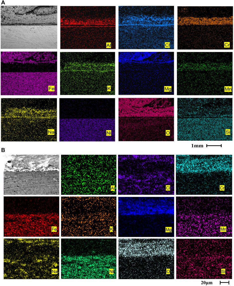
FIGURE 5. Cross-sectional morphologies and EDS mapping of two alloys after corrosion at 800 °C for 120 h: (A) AFA 310S, (B) commercial 310S
Figure 6 shows the section SEM of AFA 310S corroded for 120 h. Figure 6A displays pits of varying sizes, up to 1 mm in diameter. In the meantime, pitting and intergranular corrosion of the matrix are shown in the oxide layer. After the observation multiple of Zone A in Figure 6B was magnified to ×100, multiple layers were found at the junction between matrix and oxide layer, namely Zone C in red rectangle. As shown in Figure 6C, five layers appear at the interface between the oxide layer and the matrix layer after the magnification of observation to 1,000X in Zone B. ①②③④ are included in the oxide layer, which are mainly composed of ① magnesium and sodium oxide and chloride, ②Cr2O3, ③ chloride molten salt, ④Al2O3, and ⑤ matrix layers. In Figure 6D, layer ① has direct contact with molten salt. Although the elements of oxidation products are very complex, their main components are magnesium, oxygen, sodium and aluminum. Layer ② is a relatively dense Cr2O3 layer, but faults have appeared that seem like a breakthrough for the external molten salt to enter the matrix. Layer ③ is the molten salt layer and is discontinuous. Layer ④ is a dense continuous Al2O3 with a thickness of 20 μm. However, as part of the Cl- had entered the matrix during the early corrosion process, there were obvious corrosion pits and cracks in the matrix. Layer ⑤ is the matrix, which has obvious intergranular corrosion characteristics and many irregular voids along grain boundaries. According to the element distribution diagram of Figure 6D, Fe,Si, Ni, and Cr elements in the matrix have migrated to the oxide layer, while Mg, K, Na, and Cl in the molten salt have entered the matrix layer. For the analysis of element activity orders, K>Na>Mg>Al>Mn>Cr>Fe>Ni, and O>Cl>S, the elements with higher orders are more prone to chemical reactions. This can also be verified by the EDS cross section microscopic morphology in Figure 7.
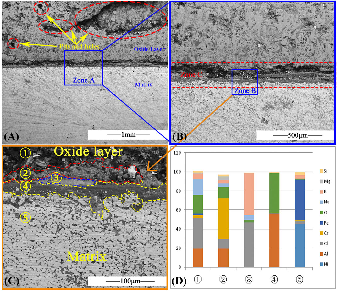
FIGURE 6. SEM result of AFA 310S cross section after 120 h at 800 °C: (A) SEM image, (B) The area of blue rectangle Zone A in (A), (C) The area of blue rectangle Zone B in (B), (D) Element of five layers of AFA 310S cross section
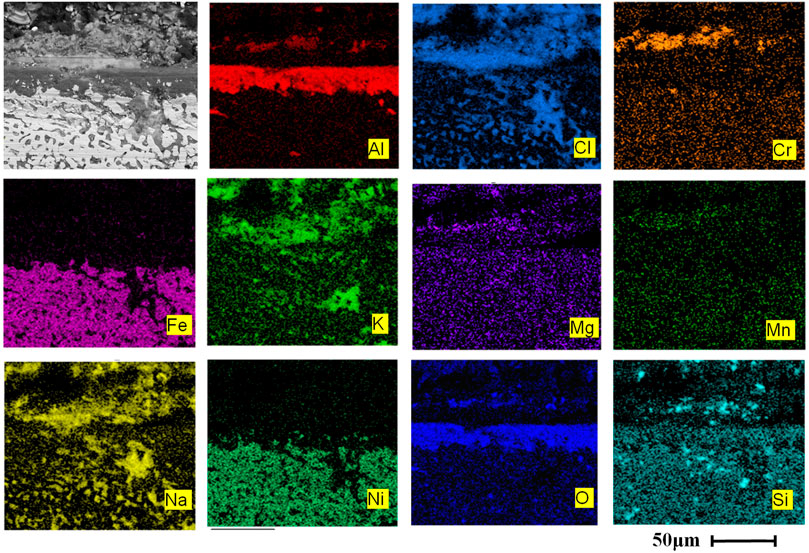
FIGURE 7. EDS mapping of AFA 310S cross section for 120h at 800 °C in chloride salt.
The cross section of the material in Figure 8A shows transverse cracks and irregular voids. The direction of the transverse crack is parallel to the substrate surface, indicating that the oxide layer might be easier to fall off in this direction. Figure 8B displays the morphology of the matrix in the cross section of the material. Many voids in yellow circles appear as a result of intergranular corrosion.
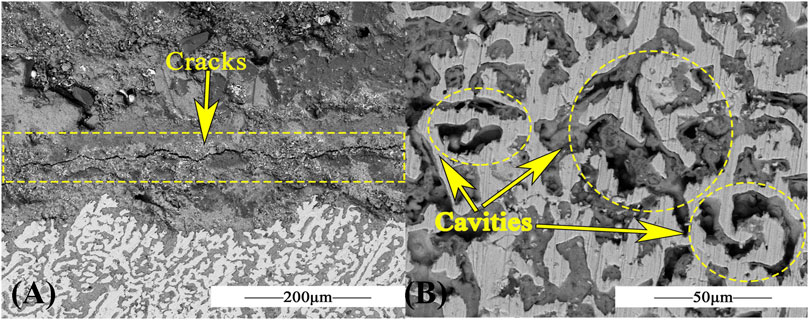
FIGURE 8. SEM of AFA 310S for 360h at 800 °C in chloride salt: (A) SEM image for cross section, (B) SEM image for matrix.
On one hand, in Figure 9, after 600 h of corrosion of AFA 310S, the Al2O3 film still exists, and the morphology are basically complete and continuous. On the other hand, the oxide formed by Fe, Cr, Mg exfoliates after numerous times of corrosion to form a thicker layer and protrusion. It indicates that the oxide film will accumulate in a certain direction as time goes by. So, this also proves that before the formation of the dense Al2O3 film, parts of Fe and Cr elements migrated from the matrix to the outside for chlorination and oxidation reactions. With the advance of chlorination reaction, Al2O3 film is also continuously eroded. O and Cl elements continuously infiltrate into the matrix, which leads to further reaction. In other words, the protective effect of passivation film on the matrix is obvious. AlCl3 can be both sublimated to a gaseous state at 800 °C and continue to generate hydrochloric acid with water, and the reaction is as follows:
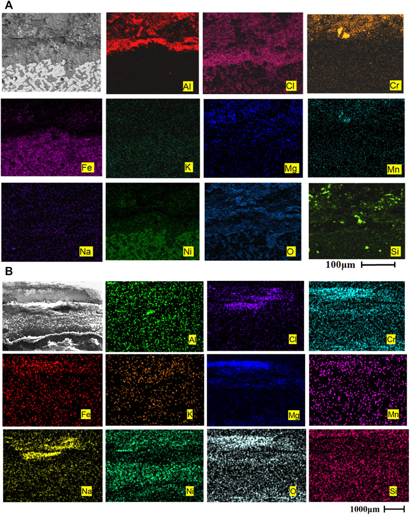
FIGURE 9. Cross-sectional morphologies and EDS mapping of two alloys after corrosion at 800 °C for 360 h: (A) AFA 310S, (B) commercial 310S
Gaseous AlCl3, HCl ,and other substances continue to escape to the outside of the oxide layer, and eventually gather into bubbles that break through the oxide layer, resulting in cavity, namely, the oxidation layer is broken, forming “channels”.
After 360 h of corrosion, the Al2O3 layer is still maintained in AFA 310S. The Si element in the matrix has moved to the outer oxide. Cl has permeated all of the matrix and oxide layers. The comparison of two the alloys shows a considerable difference that commercial 310S material has been seriously corroded without the Al2O3 and Cr2O3 layers. In other words, no continuous protective passivation film has been generated in Figure 9B, and the elements of molten salt have completely entered the matrix and generated oxidation products. The morphology of the matrix is incomplete. There is also no obvious boundary between the matrix and the oxide layer.
After 600 h of corrosion, AFA 310S has been seriously corroded in Figure 10. The outer oxide layers have formed and accumulated as a “bulge”, mainly containing Cr, Al, Mg, O, and Fe compounds. The alumina layer still exists, but it has appeared not to be dense enough and partly fallen off. According to the XRD analysis of the matrix in Figure 3, a large number of materials such as magnesionchromite, magnesium nickel manganese oxide, nickel manganese chromium oxide, and forsterite have been generated. By contrast to AFA 310S, commercial 310S has been corroded more severely, hence, the loss of metal properties.
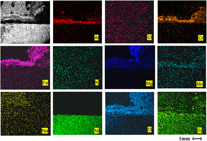
FIGURE 10. EDS element mapping of AFA 310S cross section for 600 h at 800 °C in chloride salt.
Discussion
Corrosion Mechanism in Chloride Molten Salt
In the chloride molten salt, the main corrosion mechanism of 310S stainless steel is defined as the “oxidation-chlorination” process in Figure 11. First, the initial rapid reaction stage: in the first 120 h, some chloride salts directly contact the metal surface without preoxidizing, leading to the high corrosion rates. As there is no passivation film, the reaction speed is extremely fast, and all elements of the matrix, such as Cr, Fe, and Mn, migrate to the outermost layer of the oxide layer, as shown in Figure 6. The holes and cracks that are formed gradually become channels for further reaction. The chlorine and hydrochloric acid produced by Cl- reaction continue to volatilize to the outside, while molten salt enters the matrix through the channels. Meanwhile, magnesium in molten salt reacts with oxygen to form an MgO protective film, which begins to isolate the contact between air and the matrix in order to slow down the reaction speed. The reaction was as follows: (M is a metal element)
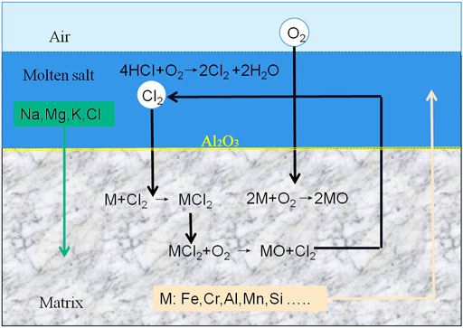
FIGURE 11. The corrosion mechanism of the alloy in chloride salt
Second, the formation stage of passivation protective film: MgO protective film has existed, and Al, Cr, Fe, Mn, Ni, and other elements in the matrix react with oxygen to form a continuous and dense protective film, Al2O3 and Cr2O3 later. In Figure 2, the passivation effect slows down the reaction speed, the corrosion rate curves clearly prove that the corrosion reaction speed decreased from 240 h.
Third, duration of oxidation and chlorination reactions: the main reasons for the failure of austenitic stainless steel are the destruction and diffusion of oxides along grain boundaries. As Cr2O3 continues to react with Cl-, the Cr2O3 film is damaged; hence the dense, continuous Al2O3 film becomes the most significant protective layer. This is proved by Gomez-Vidal’s view that alumina layers formed underneath the initial Cr2O3 layer could protect the alloy from Cl permeation because the alumina structure was dense enough (Gomez-Vidal et al., 2017b). Along with the chlorination effect occurs, the Al2O3 film is eroded by Cl-. The gaseous substance produced by the reaction is volatilized from inside to outside. Part of the oxide film is broken by the pressure of bubbles, and cracks or corrosion holes gathered to form a larger cavity. At the same time, external chloride salts also re-enter the matrix through these “channels”. This process is repeated again, resulting in the continuous thickening, breaking, and falling off of the external oxide layer, which leads to the uneven surface. With the continuous occurrence of intergranular corrosion, pitting corrosion, and fissure corrosion, the main alloying elements Fe, Al, Cr, Si, and Mn in the matrix migrate to the outer layer, resulting in the failure of the alloy. The reaction occurs as follows (Gomez-Vidal et al., 2017b):
Fourth stage, stable corrosion, all elements in molten salt enter the matrix through “channels,” and the outer oxide layer is mainly composed of MgO, iron oxide, chromium oxide, and alumina, as shown in Figure 6. The main alloy composition, such as Fe, migrates from the matrix to the oxide layer with the formation of iron oxide or other iron compounds. Corrosion continues at a slow rate because of the multiple oxide layers. In addition, due to the 600 h high temperature corrosion reaction, many stable compounds are generated, such as MgNiO2, Fe+2Cr2O4, Mg2Si2O6, NaMnO2 etc. Take Mg2Si2O6 For example (Ding and Bauer, 2021):
Five, impurities accelerate corrosion at all stages: impurities are the key factor leading to the corrosion failure, especially preventing the formation of oxidation passivation films (Fernández and Cabeza, 2020b). Impurities mainly include H2O, H+, O2, MgOHCl, etc., which have negative effects on the materials of hot tanks. At first place, dehydration of MgOHCl produces HCl, and then MgCl2 in magnesium salt is easy to absorb water and form a hydrate, which decomposes and dehydrates to generate MgO and HCl after heating. The reaction is as follows (Ding and Bauer, 2021):
Then, the impurity H2O reacts with the alkali earth metal chloride to form HCl (Guo et al., 2020):
Moreover, HCl and O2 react to form Cl2:
Finally, both HCl and H2O react with metal M to release H2:
The corrosive gases released will evaporate again from the “channels” and react with the alloy. This cycle is repeated until the material is corroded completely.
Protective Passivation Film Formation Mechanism of AFA 310S
The experimental environment is simulated under the worst conditions: 800°C, the highest temperature in the next generation of CSP, untreated atmosphere, and alloy samples without pre-oxidized. In this case, the improvement in corrosion resistance of AFA 310S alloy mainly depends on the passivation film Al2O3 formed by adding the Al element. It is also consistent with the results of many scholars. The reason can be found in the relationship between standard free energy and the temperature T:
In Figure 12, according to the relationship diagram between the standard free energy ∆G⊖ of formation of each oxide and temperature T (Xu, 2007), the greater the affinity of the metal element for oxygen is, the smaller the standard free energy is, and the more stable the oxide is. In Figure 12, MgO products are the most stable, followed by Al2O3, while Fe2O3 is the most unstable one that is easy to reduce or have other reactions (Hamdy et al., 2021). The sequencing of the activities of binding elements also reflects the important protective role of MgO in the initial rapid reaction stage. When compared with AFA 310S, commercial 310S fails to form Al2O3 film and has limited resistance of Cr2O3 film, resulting in a faster corrosion rate. Although the MgO film is constantly shedding and growing, it inhibits the occurrence of corrosion to a certain extent. But commercial 310 has been corroded and lost its metal properties in the process of chlorination reaction. The image in Figure 9 shows that the morphology of the sample corroded for 360h is not comprehensive, and after 480 h, the material matrix is basically replaced by oxide.
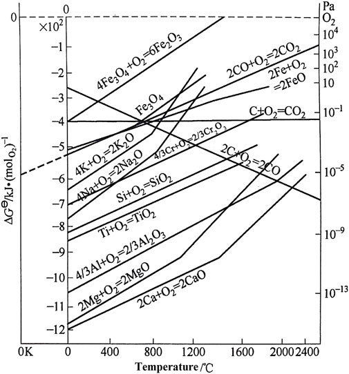
FIGURE 12. Standard free energy of formation and temperature for oxides (Xu, 2007).
Conclusion
In this paper, AFA 310S stainless steel with an aluminum addition of 2.64 wt% was prepared by thermal-aluminizing reaction. The static corrosion test was carried out using high-temperature molten chloride salt for AFA 310S and commercial 310S. The experimental results show that:
1) Due to the formation of protective Al2O3 layer in AFA 310S, it has better corrosion resistance in 800°C chloride molten salt than commercial 310S. In contrast, the commercial 310S only formed Cr2O3 and MgO for 120 h, and the oxide layer became discontinuous after 360 h.
2) Through the analysis of the corrosion products and morphology at 120, 360, and 600 h separately, it can be concluded that the corrosion mechanism of 310S stainless steel in molten chloride salt is defined as the “oxidation-chlorination” process.
3) The “oxidation-chlorination” has several stages: initial rapid reaction stage, formation of passivation protective film stage, oxidation-chlorination reaction continuous stage, and slow corrosion stage. The presence of impurities will speed up the reaction.
4) The Al2O3 protective passivation film was formed in AFA 310S, which corroded for 120 h but remained intact until 600 h. Because 2.64 wt% Al had been added into it through aluminum-thermal reaction casting method. Comparing to the commercial 310S without the Al element, this aluminum forming alloy has a certain development prospect in the application of the hot tank in the next generation CSP station.
Data Availability Statement
All data included in this study are available upon request by contact with the corresponding author.
Author Contributions
I have made substantial contributions to the conception or design of the work; or the acquisition, analysis, or interpretation of data for the work; And I have drafted the work or revised it critically for important intellectual content; And I have approved the final version to be published; And I agree to be accountable for all aspects of the work in ensuring that questions related to the accuracy or integrity of any part of the work are appropriately investigated and resolved. Thanks for all persons who have made substantial contributions to the work reported in the manuscript, including those who provided editing and writing assistance.
Funding
This work was supported by the national key research and development program “Development and application of a special alloy of high temperature molten salt for solar thermal power generation”, and “2021-2022 College-level scientific research project of Lanzhou Vocational Technical College (No.2021XY-8)”.
Conflict of Interest
The authors declare that the research was conducted in the absence of any commercial or financial relationships that could be construed as a potential conflict of interest.
Publisher’s Note
All claims expressed in this article are solely those of the authors and do not necessarily represent those of their affiliated organizations, or those of the publisher, the editors, and the reviewers. Any product that may be evaluated in this article, or claim that may be made by its manufacturer, is not guaranteed or endorsed by the publisher.
References
ASTM (2003). Standard Practice for Preparing, Cleaning, and Evaluating Corrosion Test Specimens. ASTM International Designation: United States.
Chen, H.-z., Li, B.-r., Wen, B., Ye, Q., and Zhang, N.-q. (2020). Corrosion Behaviours of Iron-Chromium-Aluminium Steel Near the Melting point of Various Eutectic Salts. Solar Energ. Mater. Solar Cell 210, 110510. doi:10.1016/j.solmat.2020.110510
Ding, W., and Bauer, T. (2021). Progress in Research and Development of Molten Chloride Salt Technology for Next Generation Concentrated Solar Power Plants. Engineering 7, 334–347. doi:10.1016/j.eng.2020.06.027
Ding, W., Shi, H., Xiu, Y., Bonk, A., Weisenburger, A., Jianu, A., et al. (2018). Hot Corrosion Behavior of Commercial Alloys in thermal Energy Storage Material of Molten MgCl2/KCl/NaCl under Inert Atmosphere. Solar Energ. Mater. Solar Cell 184, 22–30. doi:10.1016/j.solmat.2018.04.025
Fernández, A. G., and Cabeza, L. F. (2020b). Corrosion Evaluation of Eutectic Chloride Molten Salt for New Generation of CSP Plants. Part 1: Thermal Treatment Assessment. J. Energ. Storage 27, 101125. doi:10.1016/j.est.2019.101125
Fernández, A. G., and Cabeza, L. F. (2020a). Corrosion Evaluation of Eutectic Chloride Molten Salt for New Generation of CSP Plants. Part 2: Materials Screening Performance. J. Energ. Storage 29, 101381. doi:10.1016/j.est.2020.101381
Gomez-Vidal, J. C. (2017). Corrosion Resistance of MCrAlX Coatings in a Molten Chloride for thermal Storage in Concentrating Solar Power Applications. Npj Mater. Degrad. 1, 7. doi:10.1038/s41529-017-0012-3
Gomez-Vidal, J. C., Fernandez, A. G., Tirawat, R., Turchi, C., and Huddleston, W. (2017b). Corrosion Resistance of Alumina Forming Alloys against Molten Chlorides for Energy Production. II: Electrochemical Impedance Spectroscopy under thermal Cycling Conditions. Solar Energ. Mater. Solar Cell 166, 234–245. doi:10.1016/j.solmat.2017.03.025
Gomez-Vidal, J. C., Fernandez, A. G., Tirawat, R., Turchi, C., and Huddleston, W. (2017a). Corrosion Resistance of Alumina-Forming Alloys against Molten Chlorides for Energy Production. I: Pre-oxidation Treatment and Isothermal Corrosion Tests. Solar Energ. Mater. Solar Cell 166, 222–233. doi:10.1016/j.solmat.2017.02.019
Gomez-Vidal, J. C., and Tirawat, R. (2016). Corrosion of Alloys in a Chloride Molten Salt (NaCl-LiCl) for Solar thermal Technologies. Solar Energ. Mater. Solar Cell 157, 234–244. doi:10.1016/j.solmat.2016.05.052
Grosu, Y., Udayashankar, N., Bondarchuk, O., González-Fernández, L., and Faik, A. (2018). Unexpected Effect of Nanoparticles Doping on the Corrosivity of Molten Nitrate Salt for thermal Energy Storage. Solar Energ. Mater. Solar Cell 178, 91–97. doi:10.1016/j.solmat.2018.01.002
Guo, L., Liu, Q., Yin, H., Pan, T. J., and Tang, Z. (2020). Excellent Corrosion Resistance of 316 Stainless Steel in Purified NaCl-MgCl2 Eutectic Salt at High Temperature. Corrosion Sci. 166, 108473. doi:10.1016/j.corsci.2020.108473
Hamdy, E., Olovsjo, J. N., and Geers, C. (2021). Perspectives on Selected Alloys in Contact with Eutectic Melts for thermal Storage: Nitrates, Carbonates and Chlorides. Solar Energy 224, 2021. doi:10.1016/j.solener.2021.06.069
La, P., Meng, Q., Mao, L., Zhou, M., and Wei, Y. (2013). Effect of Al Element of Microstructures and Mechanical Properties of Hot-Rolled 316L Stainless Steels. ACTA metallurgica sinica 49, 6. doi:10.3724/sp.j.1037.2013.00048
La, P., Zhang, P., Liu, H., Meng, Q., and Wei, Y. (2014). Effect of Solution Treatment on Microstructure and Properties of High-Alumina 310S Steel. Trans. Mater. Heat Treat. 35, 3. doi:10.13289/j.issn.1009-6264.2014.03.014
Liu, H. (2012). Microstructure and Mechanical Properties of Hot-Rolled High Aluminum 310S and Effect of Aluminum on Action Mechanism, Master’s thesis. China(IL): Lanzhou University of Technology.
Liu, S., Liu, Z., Wang, Y., and Tang, J. (2014). A Comparative Study on the High Temperature Corrosion of TP347H Stainless Steel, C22 alloy and Laser-Cladding C22 Coating in Molten Chloride Salts. Corrosion Sci. 83, 396–408. doi:10.1016/j.corsci.2014.03.012
Liu, Z. (2008). Reserach on Effect of Al Elemet on Microstructures and Properties of Heat-Resistant Casting alloy HP40, Docter’s thesis. China(IL): Lanzhou University of Technology.
Meng, Q. (2016). “Microstructure Evolutions of As-Cast and Hot-Rolled High Aluminum 304,316L,310S Stainless Steels and Effects of Al on Microstructure, Docter’s thesis. China(IL): Lanzhou University of Technology.
Pooja, M., Ravishankar, K. S., and Madav, V. (2021). High Temperature Corrosion Behaviour of Stainless Steels and Inconel 625 in Hydroxide Salt. Mater. Today Proc. 46, 2612–2615. doi:10.1016/j.matpr.2021.02.266
Sah, S. P., Tada, E., and Nishikata, A. (2018). Corrosion Behaviour of Austenitic Stainless Steels in Carbonate Melt at 923 K under Controlled CO2-O2 Environment. Corrosion Sci. 133, 310–317. doi:10.1016/j.corsci.2018.01.031
Sarvghad, M., Steinberg, T. A., and Will, G. (2018). Corrosion of Stainless Steel 316 in Eutectic Molten Salts for thermal Energy Storage. Solar Energy 172, 198–203. doi:10.1016/j.solener.2018.03.053
Sheng, J., Jin, J., Shi, Y., Chen, W., Ma, G., Wei, J., et al. (2021). Superior Strength and Ultrahigh Ductility in Hierarchical Structured 2205 Duplex Stainless Steel from Nanoscale to Microscale. Mater. Trans. 62, 1604–1608. doi:10.2320/matertrans.MT-M2021085
Sheng, J., Wei, J., Li, Z., Man, K., Chen, W., Ma, G., et al. (2022). Micro/nano-structure Leads to Super Strength and Excellent Plasticity in Nanostructured 304 Stainless Steel. J. Mater. Res. Technol. 17, 404–411. doi:10.1016/j.jmrt.2021.12.117
Sun, H., Wang, J., Li, Z., Zhang, P., and Su, X. (2018). Corrosion Behavior of 316SS and Ni-Based Alloys in a Ternary NaCl-KCl-MgCl2 Molten Salt. Solar Energy 171, 320–329. doi:10.1016/j.solener.2018.06.094
Sun, H., Zhang, P., and Wang, J. (2018). Effects of Alloying Elements on the Corrosion Behavior of Ni-Based Alloys in Molten NaCl-KCl-MgCl2 Salt at Different Temperatures. Corrosion Sci. 143, 187–199. doi:10.1016/j.corsci.2018.08.021
Wang, J.-w., Zhang, C.-z., Li, Z.-h., Zhou, H.-x., He, J.-x., and Yu, J.-c. (2017). Corrosion Behavior of Nickel-Based Superalloys in thermal Storage Medium of Molten Eutectic NaCl-MgCl2 in Atmosphere. Solar Energ. Mater. Solar Cell 164, 146–155. doi:10.1016/j.solmat.2017.02.020
Wang, W., Guan, B., Li, X., Lu, J., and Ding, J. (2019). Corrosion Behavior and Mechanism of Austenitic Stainless Steels in a New Quaternary Molten Salt for Concentrating Solar Power. Solar Energ. Mater. Solar Cell 194, 36–46. doi:10.1016/j.solmat.2019.01.024
Keywords: aluminum-forming alloy, concentrated solar power, corrosion, molten salt, chloride, passivation
Citation: Wei Y, La P, Jin J, Du M, Zheng Y, Zhan F, Sheng J, Yu H and Zhu M (2022) Corrosion Behavior of Aluminum-Forming Alloy 310S for Application in Molten Chloride Salt CSP Thermal Storage Tank. Front. Mater. 9:886285. doi: 10.3389/fmats.2022.886285
Received: 28 February 2022; Accepted: 07 April 2022;
Published: 19 May 2022.
Edited by:
Hong Zhang, Swiss Federal Institute of Technology Lausanne, SwitzerlandReviewed by:
Yang Huang, Shenzhen University, ChinaFei Ye, The University of Hong Kong, Hong Kong SAR, China
Copyright © 2022 Wei, La, Jin, Du, Zheng, Zhan, Sheng, Yu and Zhu. This is an open-access article distributed under the terms of the Creative Commons Attribution License (CC BY). The use, distribution or reproduction in other forums is permitted, provided the original author(s) and the copyright owner(s) are credited and that the original publication in this journal is cited, in accordance with accepted academic practice. No use, distribution or reproduction is permitted which does not comply with these terms.
*Correspondence: Peiqing La, cHFsYUBsdXQuY24=