 Aaron D. Sinnott
 Owen Brazil
 Graham L. W. Cross
- Trinity College Dublin, Dublin, Ireland
Nanoindentation is the only way to test the local mechanical properties of thin films and coatings. Current analysis treats the measurement as a perturbation of a conventional half-space indentation, typically limiting testing to films with modulus within an order of magnitude of the supporting substrate and contact dimension much smaller than the film thickness. In the layer compression test (LCT), a flat punch is aligned and indented into the film with a contact size much greater than the film thickness. This produces a novel test condition emulating uniform uniaxial strain even with significant penetration into the film beyond plastic yield. In this work, we perform a finite element analysis to assess the quality of this approximation in the confined elastic regime of deformation up to the point of yield via a parametric study of punch radius to film thickness ratio and film to substrate modulus ratio for a simple elastic-plastic material. Our simulations were performed with a low E/Y ratio of 10, which is typical of polymers, biomaterials and other amorphous systems. We find that for substrates of sufficiently high stiffness relative to the film sample, once a simple substrate stiffness correction is performed the layer compression test load vs. displacement slope estimates the film confined modulus to within a few percent with only minor variation throughout the entire pre-yield strain region for a wide range of aspect ratios. We also present experimental layer compression test findings for a supported polymer film conducted over a contact aspect ratio range of 9–22 and discuss the trends observed relative to the simulations.
Introduction
Supported thin films play an important part in many technologies, as well as in the exploration of low dimensional physical size effects. Mechanical instrumented nanoindentation provides an effective, repeatable way to measure the mechanical properties of a variety of materials, with the Oliver-Pharr method of half-space indentation using an axisymmetric tip forming the standard for measuring elastic material properties with nanoindentation (Oliver and Pharr, 1992). The technique relies on measurement of the elastic response of a material during the early stages of unloading assuming a monolithic sample geometry that can at least be approximated as a half-space. It is challenging or even impossible to accurately separate out the mechanical properties of a supported thin film by this approach when the proximity of the substrate contributes substantially to the overall contact mechanics (Jönsson and Hogmark, 1984; Chechenin et al., 1995; Tsui and Pharr, 1999; Saha and Nix, 2002). Efforts to measure the mechanical characteristics of soft films with vastly lower stiffness compared to the substrate have focused on the low strain elastic properties of the films (Nix, 1989; Vlassak and Nix, 1992; Saha and Nix, 2002; Bec et al., 2006; Mujika, 2006; Xu and Pharr, 2006; Yang, 2006; Hay and Crawford, 2011; Wald et al., 2013). Notably, Wald et al. (Wald et al., 2013) investigated the problem of analysing the reduced elastic modulus of a purely elastic, elastically supported film indented by an aligned flat punch at the limit of zero-strain. While alignment of the punch face to sample surface can be challenging for thin films especially, the implicit advantage of flat punch indentation is the removal of virtually any assumption regarding the area of contact during deformation, which nominally remains constant. Unlike the Oliver-Pharr technique that relies on an assumption of the way a deforming sample contacts a presumed tip shape function with depth, a simple mean stress can be directly calculated from flat punch load data at any point during the deformation. Work investigating flat punch, supported thin film contact beyond the zero strain limit exists (Li, 2002; McManamon et al., 2020; Luo et al., 2022), but generally does not consider the high contact aspect ratio limit which renders the deformation highly uniform and allows the formation of a representative common strain exploited by the layer compression test (Brazil et al., 2020; Brazil et al., 2021).
In this work, we use finite element analysis to explore contact aspect ratio α (cylindrical, flat ended punch diameter to film thickness) flat punch indentation of an elastic simple-plastic film supported by a purely elastic substrate where the values of α were varied from 5 to 100 by changing film thickness for a fixed punch radius. The film material was simulated with a fixed modulus Efilm and yield strength Yfilm with ratio Efilm/Yfilm = 10, while the substrate modulus Esubstrate was varied over a range S= Esubstrate/Efilm from 10 to 1,000. A radially symmetric simulation was used to investigate indentation under load control to about 25% the film thickness. Our results indicate that a well aligned punch contacting a stiffly supported film at high contact aspect ratio exhibits features characteristic of uniaxial strain, demonstrated previously by our experiments with polymer films on silicon (Brazil et al., 2020; Brazil et al., 2021). With sufficient indentation depth and high enough aspect ratio, a complete mechanical parameterization of an elastic-plastic constitutive condition characterized by confined elastic modulus, bulk modulus, and yield stress can be extracted from a single loading curve (Brazil et al., 2020). More generally, a stress vs. strain curve can be generated for any constitutive behaviour well past most elastic limits allowing, for example, fundamental study of mechanisms of plasticity carriers at small scales in soft matter. Here we focus on what extent varying the substrate modulus ratio S and contact aspect ratio
Simulation of the layer compression test
The stress vs strain behaviour of the Layer Compression Test can be understood by considering the geometry and constraints imposed on the deformed region. If the indenting contact area over the film is allowed to approach infinity (ie. with contact aspect ratio
Where E is Young’s elastic modulus,
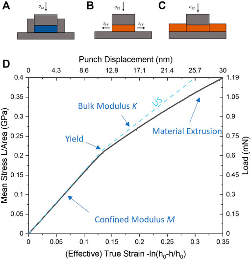
FIGURE 1. Comparative schematic of (A) pure uniaxial strain (US) with rigid wall and substrate confinement, vs. (B) unconfined flat punch puck compression vs. (C) the Layer Compression Test (LCT) where the surrounding film provides a confining sidewall effect on a puck-like region. In (D) a simulation of the LCT (black line) is compared to the theoretical expectation of uniaxial strain (blue dotted line) for a contact aspect ratio of α = 20 and elastic-plastic film with E = 1 GPa, ν = 0.35, Y = 0.1 GPa on substrate with modulus 500 GPa (S = 500). An initial linear region in the stress strain curve corresponds to elastic deformation (slope M, the confined Modulus), followed by a sudden change of slope at the confined yield point Yc to confined elastic-plastic deformation with slope K, the bulk modulus. Strains in the LCT curve past the yield point shows increasing deviation from pure uniaxial strain due to failure of the confining film material and associated extrusion.
The layer compression test replaces the finite, rigidly confined sample puck geometry with a continuous film supported by an elastic substrate and indented by a punch of equivalent area as shown in Figure 1C. Approximate uniaxial strain conditions can be maintained by high stiffness of the substrate relative to the film and high contact aspect ratio that is naturally augmented by a confining action against lateral strain in the compressed puck region by the surrounding film.
Our finite element simulations of the layer compression test were setup using the Abaqus 2019 explicit solver as follows. Radially symmetric elements were used to construct two parts representing the film and substrate. A variable scale mesh was constructed to assign a high density of elements in regions expected to experience high stress gradients near the punch edge as shown in the supplemental material (see Supplementary Figure S1). The punch was represented via an analytical flat ended cylinder surface with radius 1,000 nm and rounded corner with 50 nm radius of curvature. The edge rounding served to both represent typical manufacturing tolerances in punch microfabrication as well as improve simulation numerical stability at larger indentation strain. Five films of width 10,000 nm and thicknesses 400, 200, 100, 40 and 20 nm were simulated giving contact aspect ratios of α = 5, 10, 20, 50, and 100 with the punch. These elastic, simple plastic films had mass density 1,000 kg m−3 and was given a Young’s modulus of 1 GPa, Poisson’s ratio of 0.35, and von Mises yield stress of 0.1 GPa. The elastic substrate of dimensions 10,000 by 10,000 nm had a mass density 2000 kg m−3 and Poisson’s ratio of 0.25, while its Young’s modulus was varied among 10, 20, 50, 100, 200, 500, and 1,000 GPa to give film to substrate modulus ratios S of 10, 20, 50, 100, 200, 500, and 1,000. The film was treated as perfectly bonded to the substrate by the use of Abaqus element node ties across the shared interface, while the punch contact was treated as frictionless.
A simulated indentation stress-strain curve is shown in black in Figure 1D along with the expected analytical result of the film material under uniaxial strain (blue dashed lines). In contrast to our previous work (Brazil et al., 2020; Brazil et al., 2021), here we use “effective true strain” εT which is a more accurate representation of finite strain than simple (effective) engineering strain h/h0. This quantity is derived from our punch displacement into the film as
where h is the indentation depth and h0 is the initial film thickness. It is conceptually treated as a representative strain for the entire compressed puck region under the punch which is approximately uniform. We form a mean contact stress on the film as σT = L/A where A is the contact area of the punch to film and L is the indentation load applied to the punch. This quantity is similarly representative of all regions of the compressed puck under assumption of uniformity.
The stress vs strain curve is characterized by two linearly sloped regions, separated by a clearly defined kink which demarks a sharp transition from an elastic to elastic-plastic state of the puck of film material beneath the punch. This kink, a known feature of elastic-plastic uniaxial strain (US) (Donald Turcotte, 1982; Davis and Selvadurai, 2001), has been identified as the material’s intrinsic confined yield point occurring at yield stress Yc and appears in the LCT as well (Brazil et al., 2020; Brazil et al., 2021). In US, the initial stress-strain linear region is purely elastic deformation characterized by a confined modulus M, while beyond Yc the slope transitions to K, the bulk modulus, reflecting plastic deformation with an additional hydrostatic elastic nature where further shear stress cannot be generated due to yield.
Wald et al. (Wald et al., 2013) have used finite element analysis to study the mechanics of indenting an elastically supported, elastic thin film indented by an aligned, rigid flat punch with sharp punch edges at the limit of zero strain. They performed a fitting procedure to simulated indentation data using a simple analytical model approximating contact to the combined film-substrate system as two linear springs in series: One representing a compressed puck region with another representing compression of the substrate as uniform contact to an elastic half-space. This was done for a large range of contact aspect ratios, substrate to film modulus ratios, Poisson’s ratios and contact friction conditions to extract effective scaling constants C1 and C2 multiplying each spring constant to account for the particular complexities of differing conditions. To compare our results to theirs, we recast their semi-analytical model in terms of our uniaxial strain confined modulus M and extract our own confined modulus estimate at zero strain directly from our mean stress vs. effective true strain curves from our own fully elastic-plastic film simulations.
The zero-strain semi-analytical model developed by Wald et al. is formulated to relate the intrinsic film modulus Efilm to an effective contact modulus E*eff extracted from standard Oliver and Pharr (Oliver and Pharr, 1992) analysis of measured flat punch indentation unloading slope ΔL/Δh = kfilm-sub as
where Efilm/Esub = 1/S is the Young’s modulus ratio of film to substrate respectively, C1 and C2 are finite element derived fitting parameters introduced above, and h0 and a are the initial film thickness and radius of the indenting punch respectively (Wald et al., 2013). The last term on the right arises from series combination of the two springs described above, scaled by C1 and C2 respectively.
For comparison to Wald et al., we consider flat punch load L vs. displacement h curves from simulation or experimental measurement and form an estimate of the uniaxial strain confined modulus M which from Eq. 3 is a ratio of (punch) axial stress to axial strain
For simplicity here we have used engineering strain h/h0 which asymptotically approaches true strain at the zero strain limit. We can then form a confined modulus from Wald’s expression by combining Eqs. 6,7
where we have incorporated our own α and S ratio definitions. We will show that our simulations agree well with Wald et al.‘s results in the zero strain limit as well as establish how well our uniaxial strain interpretation of mean stress vs. effective true strain slope performs throughout the pre-yield region of indentation strain. We note that within this elastic regime, loading and unloading slopes are equivalent and in principle either can be taken to determine kfilm-sub.
Results
Figure 2 shows compiled results from the finite element simulations of the layer compression test described above, represented as mean stress vs. effective true strain for contact aspect ratios
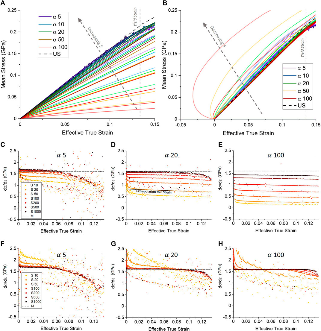
FIGURE 2. Effect of varying contact aspect ratio α and substrate-to-film modulus ratio S on mean stress vs. effective true strain in the layer compression test simulated for a 1 μm radius flat punch in frictionless contact with thin elastic-plastic films bonded to an elastic substrate. (A) Mean stress vs. effective true strain ε =-ln[(h0-h)/h0] values for all S and
Substrate compliance can be compensated for by subtracting an estimate of the direct punch-substrate contact stiffness ksub. The estimate can be made experimentally by indenting an exposed portion of the aligned substrate and subtracting the resulting stiffness measurement from that of the LCT indent (Brazil et al., 2020), or alternatively, using an analytical estimate of the substrate stiffness. In either case, the parasitic bending can be subtracted directly from punch indentation displacement h to correct the effective true strain as
where Esub and
Figures 2C–H examines in detail the slope of mean stress vs. effective true strain for cases of uncorrected (panels c to e) and substrate corrected (panels f to h) for a selection of aspect ratios (the complete set of all five aspect ratios and 7 S ratios in our study can be found in Supplementary Figure S2). While our simple substrate bending compensation fails to account for non-uniform deformations (such as the substrate deforming more towards the centre of an indent (Cross et al., 2005)), which introduces inaccuracies particularly for low S at higher
It should be noted that in Figure 2 (and in Figure 4) there exists a brief but significant deviation around the zero strain limit in all datasets. This was found to be due to a discontinuity at zero strain in our simulations which does not represent a real effect in experimental indentation (Brazil et al., 2020), and so can be discounted as a zero-strain artifact. Larger deviations from M for low S in the substrate corrected data are a result of some further limitations: Our simple substrate correction cannot account for secondary effects such as non-uniform substrate bending (a so-called “pin-cushion” effect more pronounced at low S and high
In Figure 3, we compare our simulated LCT results to that found previously by Wald et al. (Wald et al., 2013) by forming an estimate of M at zero strain. We do this by extrapolation of our uncorrected dσ/dε slope curves in Figures 2C–E to zero strain as shown by example in Figure 2D. Doing so, we avoid the small strain artefact in our data mentioned above. The results of Wald et al. are plotted as dashed lines using Eq. 8, and are found in good agreement with Wald et al.‘s results both qualitatively and quantitatively. Namely, it is clear that a stiffer substrate and higher aspect ratio increases fidelity to a uniaxial strain-like condition, with stiffer substrates needed as higher aspect ratios are used as the substrate has a higher tendency to deform at these high aspect ratios. For the configuration where our results overlap best with Wald’s (
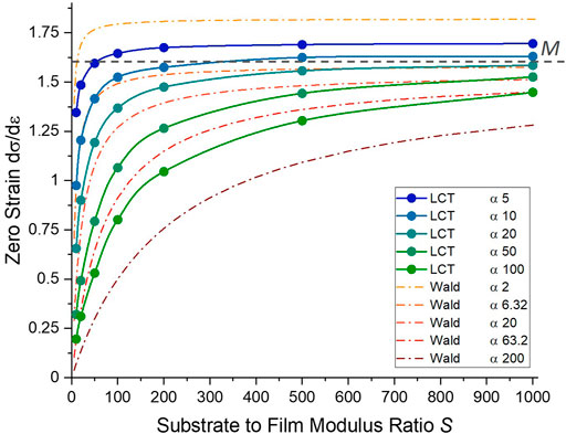
FIGURE 3. Mean stress vs. effective true strain slope of the LCT evaluated at zero strain for an elastically supported, elastic-plastic film for all simulated values of α and S (uncorrected data from Figure 2). The theoretical confined modulus M = 1.6 GPa for the film material under uniaxial strain is shown by a dotted line. For each aspect ratio there exists a critical value of S such that the slope ceases to vary rapidly and has close to constant offset from M. The results of Wald et al. (Wald et al., 2013) using Eq. 8 are plotted as dashed lines and show excellent agreement for eg. the case of α = 20.
It is clear from Figure 3 that for all aspect ratios as we increase S the extracted zero strain confined modulus M plateaus to a constant level. Conversely, in the limit of small S, where the substrate and film become indistinguishable and the indenter is in effect encountering a homogeneous elastic half-space, the value varies rapidly and is grossly underestimated. The plateau to a constant value is approached more quickly at lower aspect ratios, with much higher substrate stiffnesses required at high aspect ratio. This terminal level of the calculated confined modulus from the true value is a function of the aspect ratio of indentation, with lower aspect ratios having a higher offset. For the limiting case of a system with infinitely high substrate stiffness (ie perfect longitudinal confinement) and infinite aspect ratio (perfect lateral confinement), our results suggest that we will asymptotically approach the expected M = 1.6 GPa uniaxial strain value from below. Significantly, the results in Figure 3 show that for a given contact aspect ratio, an accurate estimate of M can be made by applying a single offsetting value for sufficiently high S.
To understand more deeply how the LCT diverges from pure US, in Figure 4 we examine the trend with α and S of the relative deviation of the LCT mean stress vs. effective true strain slope shown in Figure 2 from the expected confined modulus M for uniaxial strain. Figures 4A–C shows the deviation without the substrate compliance correction (corresponding to Figure 2A) while Figures 4D–F shows the effect of applying the correction (from Figure 2B) for seven S ratios from 10 to 1,000, with the panels corresponding to α = 5, 20, and 100. The lower aspect ratio five represents typical LCT experimental conditions explored currently, while the higher value of 20 should be achievable with incremental instrumentation improvements. The highest value of α = 100 is presented as a limiting value for the technique probably requiring significant experimental effort and instrument redesign to achieve. The complete set of substrate corrected deviations for S = 50 to 1,000 is comparatively plotted in Figure 4H. It should be noted that our simulations assumed frictionless contact between the punch and film. Punch–film friction works to limit lateral strain within the film, and as such works to increase fidelity to the US condition further than our frictionless consideration here. However this effect is more pronounced in the region of plastic deformation which is not explored in this work. This combined with the generally low frictional properties of diamond indenters used in LCT experiments limits the impact of such effects on this work.
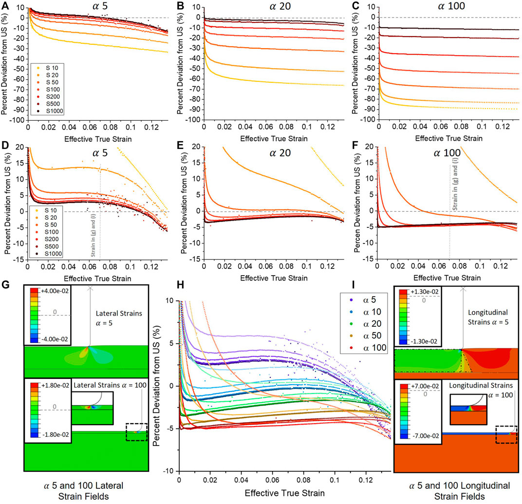
FIGURE 4. Results of Figures 2A,B re-expressed as deviation of LCT Mean Stress vs. Effective true strain relative to pure uniaxial strain up until yield strain without (A–C) and with (D–F) the substrate stiffness correction. The gradual downwards slope with strain present in all datasets is due elastic relaxation of the confining film [visualised in (G)], introducing non–uniaxial deformations into the film. An analytical substrate correction step as per Eqs. 9, 10 can reduce this error to those shown in (D–F). As discussed earlier, this simple substrate correction grossly over-compensates at low S as described for Figure 2F–H, but can otherwise reduce the error from US to less than
We first consider the uncorrected, high aspect ratio data in panel 4(c). As might be expected, the LCT slope progressively underestimates the US confined modulus with decreasing S as the combined stiffness of film and substrate under the punch is dominated by a compliant substrate. For the stiffest substrate with S = 1,000, the LCT estimates US with an almost constant −10% systematic offset all the way to the yield point of 0.136 strain. We attribute the slight downward trend in all the curves to elastic relaxation of the confining surrounding film to be discussed below. At very low strain below 0.005, the abrupt upward swing in the data is due to a minor numerical artefact of the spline-fitting procedure used to allow noise-free differentiation of the simulated data and should be ignored.
Then, moving to lower aspect ratios of 20 and 5, we see an overall shift from negative towards positive deviation for the full curves, and significant tightening of their spread with S. The latter effect is expected as the substrate stiffness influence drops as the puck stiffness is reduced by low aspect ratio (i e. the overall contact stiffness is dominated by low puck stiffness.) The general upwards trend in deviation is likely due to lack of confinement of the stress at low aspect ratio, with a downward spreading to larger volume of the combined film and substrate material resulting in the overall stiffness felt by the punch to be higher (see further discussion below.) We further note a slightly steeper downward slope for each set of curves as aspect ratio is decreased, which corresponds to weaker lateral confinement of the puck at low aspect ratio. In addition, a further negative roll-off in the deviation can be seen, for example at α = 5 and high S around 0.08 effective true strain. Examination of the simulated strain fields show this is due to onset of plasticity in the outer radial regions of the puck near the punch corner. This “premature plasticity” foreshadows the onset of the sudden and complete elastic-to-plastic transition throughout the entire puck volume. The complete transition continues to produce a distinct but less sharp kink in the stress vs. strain curves as can be seen in Figure 2A, with increasing shift away from the theoretical confined yield stress and strain point with decreasing aspect ratio. Premature plasticity generally affects only lower aspect ratios as can be seen by its delayed (panel (b)) or almost non-existent (panel (c)) presence.
Applying the substrate compliance correction has a large effect on the trend with S, completely inverting the deviation towards overestimating US with decreasing S while also creating large variance in the deviation with strain for small S. For large S, the effect is smallest manifesting as a decrease in the α = 100 error from (approximately) −10% to −5% and from +5% to +2.5% for α = 5. For high values of S, the correction leaves a predominantly constant deviation that subtly rises and peaks before yield for all aspect ratios. In the case of α = 5, we see an initial gentle upwards trend towards less negative deviation, only to peak around 0.05 to 0.06 effective true strain with increasingly sharp roll-off as the yield strain is approached. While the roll-off remains clearly a result of premature plasticity discussed above, this gentle increase is attributed to the rounded corners of the punch coming into contact with the film. This results in a small but gradual increase in the contact area which works to act in opposition to an initial small underestimate of the true contact area caused by assuming a punch radius more accurately than would typically be assumed during experiment (discussed further below). This effect is more pronounced for lower
In Figures 4G,I we examine the detailed strain fields within the compressed puck and surrounding film calculated within the finite element simulations. In pure US, the puck material experiences uniform longitudinal strain parallel to the loading direction (Wang, 2017). In the LCT, non-uniform strains develop in the film at stress riser locations like the punch corner. To analyse divergences, radial cross-sections of the elastic strain fields at different effective strains and aspect ratios were analysed. Deviations from the US ideal of homogenous, longitudinal compression of a perfectly confined puck (two of which are explained in detail below for Figures 4G,I) were analysed numerically by first considering the size of a given strain divergence compared to the compressed puck region (taking into account radial effects on the area occupied by each divergence), and then adjusting for the magnitude of the strain in that divergent region compared to the magnitude of longitudinal strain within the puck volume. This gives a fractional consideration of how much of the overall strain experienced in the puck at any one instant is governed by the US-like longitudinally compressed puck, and how much is deviatory strain behaviour.
In Figure 4G, radial cross-sections reveal the development of concentrated lateral strain gradients at both low (α = 5, upper panel) and high (α = 100, lower panel) aspect ratio contact with the punch penetrating to 0.05 effective true strain. In both geometries these propagate downwards and laterally into the film as two lobes: Under the punch in the puck region a positive radial displacement develops that is mirrored by a second lobe with a negative radial character in the surrounding film region. Critically, at high aspect ratio the spreading is arrested by close proximity of the substrate and thus non-uniform deviation constitutes a lower fraction of the overall deformed volume. A second deviation arises from the transmission of normal stress from the punch through the film to the substrate. This is revealed in Figure 4I as the distribution of normal direction strain in the film, showing a spreading effect beyond the punch contact periphery. This effect is clearly more pronounced for low aspect ratio contact (upper panel vs. lower panel.) We propose that the net effect of these non-uniformities is to cause deviations of the LCT stress vs. strain curve from pure US in opposing directions. For the lateral strain lobes, a more compliant puck volume is created that translates to a lower value of stress for given strain. Conversely, the spreading of normal stress to a wider region of the substrate renders both the effective diameter of compressed puck and area of the compressed substrate higher, creating an overall stiffer response. In both cases, non-uniform regions represent larger fractions of the deformed volumes at lower aspect ratio.
Taking stock of our results as presented in Figure 4H, we see that at presumed best case scenario of high α and high S, we find a deviation of ∼ −5% from the expect value of M at zero strain, rising to about −3.5% just before rolling off at yield. The overall mean offset of this curve can be accounted for from the way the mean stress was calculated from the punch load given by the finite element analysis. In order to closely emulate experimental conditions and practice, mean stress was calculated dividing the load by a constant punch face area value computed assuming a contact radius of a-r/2, where r is the punch corner rounding. Such a mean value might be determined eg. via optical characterization of the punch dimensions not able to resolve nanoscopic rounding. Careful examination of the strain field during contact reveals that pre-yield, the punch to sample contact radius remains very close to the initial contact radius of a-r, in our case 950 nm for a 1,000 nm radius punch with r = 50 nm corner rounding radius. A simple analysis shows we should expect a ∼5% relative underestimate of the US stress due to an overestimate of the contact area as we indeed find for the case of
In Figure 5 we present experimental LCT results performed with an a = 2050 nm radius diamond flat punch indenting atactic (amorphous) polystyrene (aPS) layers of thickness 190, 240, 300 and 470 nm spin coated onto flat Si(100) substates. This polymer features a low E/Y ratio of ∼10, close to the simulated value of 10 and typical of soft materials with significant free volume (such as a range of glassy materials and amorphous polymers) most appropriate for the LCT. Detailed punch and sample preparation procedures are provided in our previous publications (Brazil et al., 2020; Brazil et al., 2021); here they give a value of S ∼ 22 for expected aPS modulus of 3.1 GPa and Si(100) modulus of 70 GPa with a range of aspect ratios α = 8.8, 13.6, 17, and 21.6. Load vs. displacement measurements for each film in panel 5(a) show the kink expected for a confined yield event, while the overall slope of each curve increases with decreasing film thickness as expected for higher aspect ratios. The upward curvature at very small displacements is due to a small misalignment between punch face and film (Brazil et al., 2020). In Figure 5B, conversion of load and displacement to mean stress and substrate compliance corrected effective strain collapses the data to a common locus throughout the pre-yield kink regime. The slope of the data agrees well with the typical range of confined modulus slope of aPS found in the literature from M = 4–5.46 GPa slope (green dotted lines, based on the range of Poisson’s ratio for aPS from ν = 0.32 to 0.35 and Young’s modulus E from 2.8 to 3.4 GPa) Effects of aspect ratio predicted by the simulations can be seen even over this relatively small range: At high strain, the lower aspect ratios start to roll off, indicative of premature plasticity. This plasticity at the punch edge is evidenced by AFM scanning [see for example Figure 3 of (Brazil et al., 2020)] of the residual punch contact that shows a thin circular moat left behind when unloading is performed just before yield (while any penetration beyond the yield point leaves a full crater from the plasticized puck across the full contact zone.)
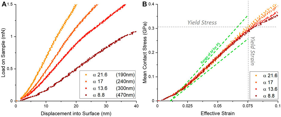
FIGURE 5. (A–B) Experimental LCT results using a 4.1
Our comparison to polymer data highlights an important issue of identifying a calibration sample for the layer compression test. The LCT requires reasonably high value of substrate to film modulus ratio S, a value that will be fundamentally capped by diamond with the highest modulus in nature. The modulus of engineering materials like silicon, sapphire or even diamond likely limits the test to films with stiffness at most that of soft metals to maintain high accuracy. Moving to much softer films like polymers, biomaterials, etc. as a reference immediately presents the problem of their non-equilibrium state that is often strongly dependent on sample preparation history as evidenced in the range of values we present in Figure 5. Thus, the potential candidates for a reference material appear quite limited in number. The candidate must also possess a Poisson’s ratio that is not too high (eg. less than ∼0.4) as high lateral expansion in the film will also cause large deviations from uniaxial strain. Some exotic materials like Europium (E = 14.5 GPa,
Conclusion
We have presented a finite element numerical analysis of the effect of punch radius to film thickness contact aspect ratio α and substrate to film elastic modulus ratio S on the veracity of the layer compression test to emulate uniaxial strain within an elastic-simple plastic, elastically supported film with E/Y ratio of 10, up to the nominal confined yield true strain of 0.136. For sufficiently high S we find the LCT provides a reasonable approximation of US for all tested α in this region of strain. This manifests as a nearly constant mean stress vs. effective true strain slope with a small offset (<10%) that is a complex but explainable function of α, S and geometric defects like punch edge rounding. Extracted at zero strain, our results match well with previous reports of elastically supported elastic films when recast in term of the uniaxial strain confined modulus M. Experiments conducted over a limited range of α and at S ∼ 20 for a polymer film on silicon substrate agree with both the expected deviation with the confined modulus estimate as well as qualitative trends we see in simulation. Future work will explore larger strains encompassing the yield point and beyond into the zone of confined plasticity, as well as a range of Poisson’s ratio and high E/Y ratio materials like metals and ceramics within limits provided by their high intrinsic moduli.
Data availability statement
The raw data supporting the conclusions of this article will be made available by the authors, without undue reservation.
Author contributions
AS: Performed simulation, analyzed results, write paper GC: Performed simulation, analyzed results, write paper OB: Experimental work for Figure 5 on thin film aPS.
Conflict of interest
The authors declare that the research was conducted in the absence of any commercial or financial relationships that could be construed as a potential conflict of interest.
Publisher’s note
All claims expressed in this article are solely those of the authors and do not necessarily represent those of their affiliated organizations, or those of the publisher, the editors and the reviewers. Any product that may be evaluated in this article, or claim that may be made by its manufacturer, is not guaranteed or endorsed by the publisher.
Supplementary material
The Supplementary Material for this article can be found online at: https://www.frontiersin.org/articles/10.3389/fmats.2022.906204/full#supplementary-material
References
Bec, S., Tonck, A., and Loubet, J. L. (2006). A simple guide to determine elastic properties of films on substrate from nanoindentation experiments. Philos. Mag. 86 (33-35), 5347–5358. doi:10.1080/14786430600660856
Brazil, O., de Silva, J. P., Chowdhury, M., Yoon, H., McKenna, G. B., Oliver, W. C., et al. (2020). In situ measurement of bulk modulus and yield response of glassy thin films via confined layer compression. J. Mater. Res. 35 (6), 644–653. doi:10.1557/jmr.2020.42
Brazil, O., de Silva, J. P., Pethica, J. B., and Cross, G. L. W. (2021). Extrinsic plastic hardening of polymer thin films in flat punch indentation. Philos. Mag. 101 (11), 1327–1342. doi:10.1080/14786435.2021.1900615
Chechenin, N. G., Bøttiger, J., and Krog, J. P. (1995). Nanoindentation of amorphous aluminum oxide films I. The influence of the substrate on the plastic properties. Thin Solid Films 261 (1), 219–227. doi:10.1016/s0040-6090(94)06490-3
Cross, G. L. W., O’Connell, B. S., and Pethica, J. B. (2005). Influence of elastic strains on the mask ratio in glassy polymer nanoimprint. Appl. Phys. Lett. 86 (8), 081902. doi:10.1063/1.1868074
Davis, R. O., and Selvadurai, A. P. S. (2001). Plasticity and geomechanics. Cambridge: Cambridge University Press.
Hay, J., and Crawford, B. (2011). Measuring substrate-independent modulus of thin films. J. Mater. Res. 26 (6), 727–738. doi:10.1557/jmr.2011.8
Jönsson, B., and Hogmark, S. (1984). Hardness measurements of thin films. Thin Solid Films 114 (3), 257–269. doi:10.1016/0040-6090(84)90123-8
Li, J. C. M. (2002). Impression creep and other localized tests. Mater. Sci. Eng. A 322 (1), 23–42. doi:10.1016/s0921-5093(01)01116-9
Luo, M., Yang, W., Cartwright, T. N., Higgins, J. M. G., and Chen, J. (2022). Simultaneous measurement of single-cell mechanics and cell-to-materials adhesion using fluidic force microscopy. Langmuir 38 (2), 620–628. doi:10.1021/acs.langmuir.1c01973
McManamon, C., Cameron, A., de Silva, J. P., Daly, R., O'Brien, F. J., and Cross, G. L. (2020). Effect of cross-linking and hydration on microscale flat punch indentation contact to collagen-hyaluronic acid films in the viscoelastic limit. Acta Biomater. 111, 279–289. doi:10.1016/j.actbio.2020.04.043
Mujika, F. (2006). On the difference between flexural moduli obtained by three-point and four-point bending tests. Polym. Test. 25 (2), 214–220. doi:10.1016/j.polymertesting.2005.10.006
Nix, W. D. (1989). Mechanical properties of thin films. Metall. Trans. A 20 (11), 2217–2245. doi:10.1007/bf02666659
Oliver, W. C., and Pharr, G. M. (1992). An improved technique for determining hardness and elastic modulus using load and displacement sensing indentation experiments. J. Mater. Res. 7 (6), 1564–1583. doi:10.1557/jmr.1992.1564
Saha, R., and Nix, W. D. (2002). Effects of the substrate on the determination of thin film mechanical properties by nanoindentation. Acta Mater. 50 (1), 23–38. doi:10.1016/s1359-6454(01)00328-7
Tsui, T. Y., and Pharr, G. M. (1999). Substrate effects on nanoindentation mechanical property measurement of soft films on hard substrates. J. Mater. Res. 14 (1), 292–301. doi:10.1557/jmr.1999.0042
Vlassak, J. J., and Nix, W. D. (1992). A new bulge test technique for the determination of Young's modulus and Poisson's ratio of thin films. J. Mater. Res. 7 (12), 3242–3249. doi:10.1557/jmr.1992.3242
Wald, M. J., Considine, J. M., and Turner, K. T. (2013). Determining the elastic modulus of compliant thin films supported on substrates from flat punch indentation measurements. Exp. Mech. 53 (6), 931–941. doi:10.1007/s11340-012-9705-2
Wang, H. F. (2017). Theory of linear poroelasticity with applications to geomechanics and hydrogeology. Princeton: Princeton University Press, 116–149.
Xu, H., and Pharr, G. M. (2006). An improved relation for the effective elastic compliance of a film/substrate system during indentation by a flat cylindrical punch. Scr. Mater. 55 (4), 315–318. doi:10.1016/j.scriptamat.2006.04.037
Keywords: nanoindentation, thin film, nanomechanics, layer compression test, flat punch
Citation: Sinnott AD, Brazil O and Cross GLW (2022) The effect of contact aspect ratio and film to substrate elastic modulus ratio on stress vs. strain up to the point of yield during flat punch thin film indentation of an elastic-plastic film. Front. Mater. 9:906204. doi: 10.3389/fmats.2022.906204
Received: 28 March 2022; Accepted: 30 September 2022;
Published: 13 October 2022.
Edited by:
Sheng-Rui Jian, I-Shou University, TaiwanReviewed by:
Garth W. Scannell, Corning Inc., United StatesWeilin Deng, Brown University, United States
Copyright © 2022 Sinnott, Brazil and Cross. This is an open-access article distributed under the terms of the Creative Commons Attribution License (CC BY). The use, distribution or reproduction in other forums is permitted, provided the original author(s) and the copyright owner(s) are credited and that the original publication in this journal is cited, in accordance with accepted academic practice. No use, distribution or reproduction is permitted which does not comply with these terms.
*Correspondence: Graham L. W. Cross, Y3Jvc3NnQHRjZC5pZQ==