 Cecilia Scazzoli
 Robin Trigueira
 Amaël Cohades
 Véronique Michaud
- 1CompPair Technologies Ltd., Lausanne, Switzerland
- 2Laboratory for Processing of Advanced Composites (LPAC), École Polytechnique Fédérale de Lausanne, Lausanne, Switzerland
The present work investigates a novel and practical method to evaluate the healing efficiency of carbon-reinforced polymer composites. The method should be representative of damage occurring during the lifetime of a composite part, should tend to damage the healable matrix mostly and yet be simple and cost-effective to set up. Thus, the capacity to recover low-velocity impact damage has been evaluated via three-point bending flexural tests. Carbon-reinforced composite laminates were produced using HealTech™ T300-TW200-42RW-1250, a commercial healable resin pre-impregnated Torayca T300 3K twill 2 × 2 fabric with an aerial weight of 200 g/m2. Fibers were oriented at ± 45° or at 0°–90°, and the laminates were impacted at different energy levels. Flexural properties of undamaged, damaged, and healed samples were compared, and the healing efficiency was calculated as the ratio of healed and undamaged ultimate flexural strength or modulus. Since matrix healing efficiency is the value to characterize, it was shown that ±45° laminates could be tested without major fiber damage and, thus, provide the best matrix healing efficiency results. Such a method proved to be 1) representative of early-stage damage of composite FRPs often occurring in the form of delamination or matrix microcracking, and 2) a fast and reliable characterization technique requiring the use of a limited amount of material.
Introduction
Because of their excellent strength-to-weight ratio, fiber-reinforced polymers (FRPs) are nowadays increasingly used for many structural applications in the aerospace, automotive, wind, marine, and sports industries. Epoxy resins are often chosen as a matrix for their high glass transition temperature (Tg), stiffness, and solvent resistance, but unless these are toughened, as, for example, in the aerospace field, they have a major drawback: brittleness. As cracks are generally not visible on the part surface, the industry practice is to periodically inspect composite components with expensive non-destructive techniques, including x-ray or ultrasound-based methods. If a very extensive damage zone is detected, parts are simply changed and discarded, generating large amounts of waste. Alternatively, when damage is rather localized but compromises the structural integrity, costly, invasive, and time-consuming techniques have been developed for on-site repair (Katnam et al., 2013). According to Suschem (2018), the consequence of this modus operandi (cumbersome repair techniques and the generation of a large amount of waste) is the production of 40,000 tons of composite waste annually, either as scraps or defective parts, just in Europe. By the end of 2015, it was estimated that 304,000 tonnes of composite waste were produced worldwide, and most of them lay in landfills (Suschem, 2018). Projections estimate that by 2025, the composite waste will be 683,000 tonnes (Assocompositi, Anev and Futura, 2021).
An alternative exists and consists in addressing damage at an early stage, that is, in the form of microcracks and delamination, which, extending progressively, may lead to catastrophic failure. The growing research in the self-healing composite field started exactly with this purpose, taking inspiration from natural phenomena, such as bone regeneration and blood repaired clotting (Urdl et al., 2017). Extrinsic and intrinsic approaches have been developed. The first relies on the introduction of isolated reservoirs of a healing agent, which break during damage events and fill the cracks and then polymerize, while the second one relies on functionalities of the polymeric matrix itself. The scientific literature in this field is vast (Cohades et al., 2018; Kanu et al., 2019), but only a few examples are found that reached an industrial stage. One of these is vitrimers, “associative” covalent adaptable networks (CANs) (Si et al., 2020), a polymer material that can rearrange its molecular architecture with the aid of heat, thanks to exchange reactions between crosslinks while maintaining permanent organic networks, excellent solvent resistance, and fixed crosslink density. Another approach, now commercially provided by CompPair Technologies Ltd., is HealTech™, a prepreg enabling the building of FRP parts in which repair can be triggered simply with the application of moderate heat while retaining enough stiffness and strength to remain structural during healing (Cohades and Trigueira, 2020).
No matter what the self-healing approach is, apart from the main challenge of maintaining a high volume fraction of the reinforcing fibers and adequate mechanical properties for the healable composite, another critical point is represented by the difficulty in finding a common healing efficiency testing method, shared among all the scientific community. The most frequently adopted test methods are either non-destructive analysis, such as C-scans, or are based on mechanical tests such as Mode I double cantilever beam (DCB), tapered double cantilever beam (TDCB), Mode II end-notched flexure (ENF) testing, compression after impact (CAI), bending after indentation, fatigue, and tensile, and bending testing (Tesoro and Sastri, 1990; Meure et al., 2009; Park et al., 2009; Williams et al., 2009; Patrick et al., 2014; Luterbacher et al., 2015; Manfredi et al., 2015; Hia et al., 2016; Lucas et al., 2016; Sordo and Michaud, 2016; Zhang and Li, 2016; Cohades and Michaud, 2017a, 2017b; Cohades et al., 2018; Hostettler et al., 2019; Kanu et al., 2019; Beylergil, 2021; Kamble et al., 2021; Jony et al., 2022; Kamble et al., 2022).
In Mode I DCB and Mode II end-notched flexure (ENF) testing, the composite samples undergo loading–unloading cycles that allow to record force–displacement curves and crack advancement. Healing efficiency can then be defined on stiffness-based or interlaminar fracture toughness calculations (Cohades and Michaud, 2017b) (Meure et al., 2009; Patrick et al., 2014; Cohades and Michaud, 2017b; Beylergil, 2021).
TDCB testing is still a Mode I quasi-static fracture test analogous to DCB. Both techniques allow a very good crack propagation control but imply extended damage, which is not truly demonstrative of typical damage events in composites. In addition, the residual deformation of the sample after crack propagation often imposes to clamp the ends of the sample in order to bring the crack faces together, which brings added complexity to the analysis of the healing efficiency.
Fatigue damage has proved to be an issue for many different industries where composites are used, for example, marine and aerospace, and it can be truthfully reproduced at the lab-scale. Therefore, proving that self-healing FRPs can recover such damage has been of great interest. Examples of fatigue damage recovery assessment are reported by Michaud and Cohades (2019) and Kamble et al. (2021) and (2022). The only drawback of this method relies on the amount of time and material needed for a full test campaign.
Static bending tests to assess the healing efficiency have been performed by Park et al. (2009), Sordo and Michaud (2016), and Kamble et al. (2021) and (2022). The main limitation of this type of test is represented by the difficulty in the control of the damage imparted to the sample. This is either too extensive and entails fiber breakage (that cannot be repaired via a self-healing polymer matrix) or too weak to be representative of delamination or microcracking occurring through the lifetime of a composite component.
C- scans allow to quantitatively measure the damaged area, but a damage threshold needs to be set. For example, Cohades and Michaud (2017a) defined it as the location where 80% of the sound is attenuated. Composite weakness in out-of-plane loading represents one of the main drawbacks of FRPs, and hence CAI tests are particularly of interest (Williams et al., 2009) (Cohades and Michaud, 2017a). This test evaluates the residual properties in the plane after an impact, which takes place in the out-of-plane direction. Low-velocity impacts are especially relevant because they are the most demonstrative of in-service damage, including matrix microcracking and interfacial debonding (frequent in aerospace, for example, during maintenance, and leading to a decrease in strength and durability) (Katnam et al., 2013). The main drawback of this test relies on the large amount of time and material needed to obtain relevant data, making screening tests too costly and lengthy. A similar alternative, which has been frequently reported in the literature, is represented by flexural tests after indentation (Pang and Bond, 2005; Trask and Bond, 2006; Williams et al., 2007). Indentation is chosen as a method to introduce pseudo-impact damage, but it is not fully representative of realistic damage conditions (Williams et al., 2007). Samples are placed on a steel ring support and statically loaded with an indenter of 4.63–5 mm diameter until a certain maximum force is attained. Such small indenter diameters force to impart pseudo impacts whose corresponding energy is quite low, 0.5–0.7 J. Furthermore, indentation entails less harsh conditions on the matrix, which is the self-healing component of the composite.
The various methods to characterize healing efficiency exhibit many differences, and this makes the comparison of self-healing systems difficult. Furthermore, such methods are often either not fully representative of real damage occurring throughout the lifetime of a composite part, are cumbersome, or require the use of large amounts of material.
The present work aimed at presenting a rapid and efficient solution to overcome the described limitations, using HealTech™ composites to demonstrate the principle. Composite samples were first damaged via low-velocity impact, as relevant for the aerospace industry but also for the sports and marine industries. For example, impact is one of the main sources of damage to bike frames, and it forces users to go through non-destructive analysis to ensure a constant safety level, as the consequences of a hit or a crush are not always visible with naked eyes from the outside (Bowkett and Thanapalan, 2017). The capacity to mend impact damage has then been evaluated via 3-point bending flexural tests, comparing the flexural modulus and ultimate flexural strength of pristine, impact-damaged, and healed samples. Healing efficiency was thus computed as the recovery in flexural modulus and ultimate flexural strength. This approach is similar to what has been reported by Kling and Czigány (2014), but the present work includes an analysis of the influence of fiber orientation on the healing efficiency. Furthermore, a wood panel, instead of a rubber sheet with a Shore A hardness 64, was used as a support for the specimens. Overall, a simple and industrially relevant test that can be further used as a benchmark for many commercial applications is proposed in the following sections.
Materials and Methods
Materials
Carbon-reinforced composite laminates were produced using HealTech™ T300-TW200-42RW-1250, a commercial healable resin pre-impregnated Torayca T300 3K twill 2 × 2 fabric, with an aerial weight of 200 g/m2, provided by CompPair Technologies Ltd. HealTech™ resin is a thermoset-based system. The physical action occurring during the healing phase is the activation under moderate heat of a part of the resin (healing part) that undergoes a phase transformation, enabling it to flow and fill the damage (cracks and delamination), keeping it filled under the reverse phase transformation when the temperature is decreasing.
HealTech™ is used as a benchmark and, according to previous CAI and fatigue tests complemented by optical microscopy observation, is expected to heal resin damage cracks up to 100 µm thick (Cohades and Trigueira, 2020). Two different types of layups were chosen: [(0/90)]18 and [(+45/−45)]18. Laminates were cured under vacuum in an oven at 140°C for 3 h and post-cured at 180°C for 2 h. The obtained fiber volume fractions for the cured laminates were 52.93 ± 0.33% and 50.71 ± 0.36%, respectively, for the [(0/90)]18 and [(+45/−45)]18 layups.
Impact Methodology
The plates, 150 mm by 130 mm in size, were cut into rectangular samples 13 × 100 mm2, 4 mm thick. On the one hand, for [(0/90)]18 laminates, five types of samples with different treatments were prepared: 1) virgin (V), undamaged, 2) damaged 1 m (D1), 3) damaged 2 m (D2), 4) healed 1 m (H1), and 5) healed 2 m (H2). On the other hand, for [(+45/−45)]18 laminates, three types of samples were prepared: 1) virgin (V), undamaged, 2) damaged 2 m (D2), and 3) healed 2 m (H2). Damaged samples (D1 and D2) are defined as samples which have been subjected to repetitive low-velocity impacts with the aid of an impact machine built and customized for the presented test campaign. A wood panel was used as a support for the specimens, which were impacted 30 times, always in the same location, the center of the sample, via a free fall from 1 m (D1) or 2 m height (D2) of a steel impactor of 73 mm in diameter. An electromagnet enabled the release of the impactor in a controlled way. The equivalent corresponding energy of each impact was, respectively, 6.86 J and 13.72 J. A picture of the impact set-up is visible in Figure 1. Healed samples (H1 and H2) were impacted as described and subsequently placed in an oven at 150°C for 30 min to repair the created delamination before testing. Such temperature was chosen so as to be sufficiently high to activate the healing agent and, at the same time, it was below the Tg of the material to avoid inducing any degradation and preserve sufficient strength and rigidity to Guarantee structural performances.
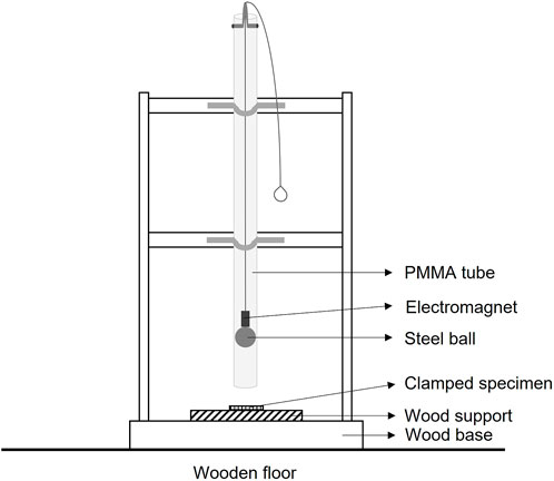
FIGURE 1. Schematic diagram of the impact setup used to damage the specimens.
In addition, as a reference test to check the influence of the healing cycle on the virgin material properties, three [(+45/−45)]18 carbon FRPs samples (VC) were subjected to conditioning, that is, a preventive healing cycle (30 min at 150°C).
All test variants are summarized in Table 1.
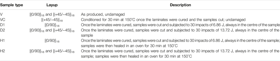
TABLE 1. Description of the different types of analyzed and tested samples.
Morphological Characterization
The cross-section of D2 samples prior to flexural tests was observed using a Keyence VHX-5000 in reflection digital microscopy to assess the type and extent of damage induced by the impact procedure in [(0/90)]18 and [(+45/−45)]18 samples.
3-Point Bending Flexural Tests
Three-point bending flexural tests were conducted on 100 × 13 mm2 samples, following the standard ASTM D7264. At least three samples per condition were tested. A 125 kN load cell for the [(0/90)]18 samples and a 10 kN load cell for the [(+45/−45)]18 samples were, respectively, installed on a universal tensile machine (UTM) Series LFM-125kN (Walter & Bai) with a span-to-thickness ratio of 16:1. The testing speed was set at 1 mm/min for the [(0/90)]18 samples and 3 mm/min for the [(+45/−45)]18 samples.
VC samples were tested to assess the influence of the healing process on the surface roughness of the samples and any influence on their flexural mechanical properties.
The healing efficiency, η, is generally computed based on the assessment of the recovery of a given property (P), in this case, the flexural modulus, E, and the maximum flexural strength, σ, from the damaged state, as compared to the loss in property after damage:
Another method is to directly evaluate the recovered properties, comparing healed and virgin properties without taking into account the damaged property (Cohades et al., 2018), such as
Both methods have been compared in this work.
Results and Discussion
Flexural Tests
Figure 2A shows the typical 3-point bending curves obtained for the V, D1, and H1 specimens with fibers at 0/90°, while Figures 2B and C depict a summary of the flexural modulus and flexural strength for those samples. The average healing efficiency computed according to Eq. 1 in terms of recovery of flexural modulus and flexural strength resulted to be 37.9% and 33.8%, respectively. This low healing efficiency can be attributed to the limited damage extent imparted when impacting from 1 m height, especially as referred to the flexural modulus. This latter decreased by 12.87% in D1 samples as compared to V ones. Considering the standard deviation in each batch of measurements, the flexural modulus of V, D1, and H1 all fall within the same range, so it appears that a minimal damage extent is needed to reach a meaningful healing efficiency. Flexural strength was lowered by 31% and was partially regained after healing. This indicated that probably some fibers were broken during the damage event D1. When calculating healing efficiency according to Eq. 2, the recovery of flexural modulus was 92%, while that of strength was 79%. This indicated that the second method is complementary and better adapted to show the healing efficiency of samples that underwent minimal damage. This also indicated that for a test to be discriminating, a degree of damage beyond the standard deviation of the property is required.
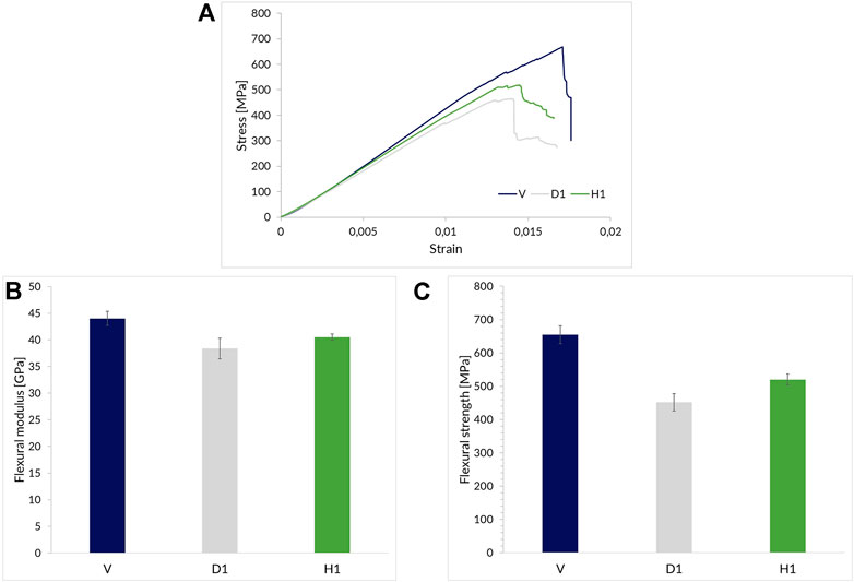
FIGURE 2. (A) Examples of 3-point bending test curves for [(0/90)]18 V, D1, and H1 samples, and (B) the flexural modulus and (C) the flexural strength for V, D1, and H1 [(0/90)]18 specimens.
Figure 3A shows the typical 3-point bending curves obtained for the V, D2, and H2 specimens with fibers at 0/90°. In this case, the difference in mechanical behaviour between the three types of samples is already obvious from an observation of these curves and from pictures displaying the side surface of the samples during 3-point bending tests (Figure 4). For V samples, failure starts with fiber breakage at the outer top surface plies which are solicited in compression and is followed by the rupture of other fibers in lower plies solicited in traction, resulting in an abrupt loss of strength (Figure 4A). In the case of D2 samples, delamination and cracks induced by impact damage act as sites for the initiation of interlaminar fracture during the flexural test (Figure 4B). H2 samples behave in an intermediate way. As observed in Figure 4C, an interlaminar fracture is present to some extent, but it is less relevant than in damaged samples, and fiber breakage also takes place, as it is also visible from the step decrease in strength throughout the flexural test (Figure 3A). Figures 3C and D show a zoom on the curves’ areas representative of the flexural modulus for both samples with fibers oriented at 0/90° and ±45°. For samples with fibers oriented at ± 45°, it can be similarly observed that the failure mode changes depending on whether they are V, VC, D2, or H2. As observed on both bending test curves (Figure 3B) and pictures taken throughout the flexural tests (Figure 5), D2 specimens underwent interlaminar fracture, which was either localized close to the impact area, the center of the sample (Figure 5C), or propagated until the edge of the sample (Figure 5D). Unlike D2 samples, V, VC, and H2 specimens all displayed the same failure behaviour, and the interlaminar fracture was not visible after healing, which can be considered the first proof of efficient healing.
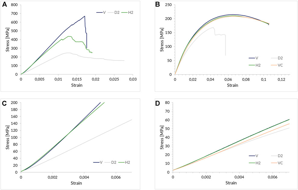
FIGURE 3. Examples of 3-point bending test curves for (A) [(0/90)]18 V, D2, and H2 samples and (B) [(+45/-45)]18 V, VC, D2, and H2 samples. (C) and (D) depict a zoom on the curves’ areas representative of the flexural modulus, respectively, for samples with fibers oriented at 0/90° and ±45°.
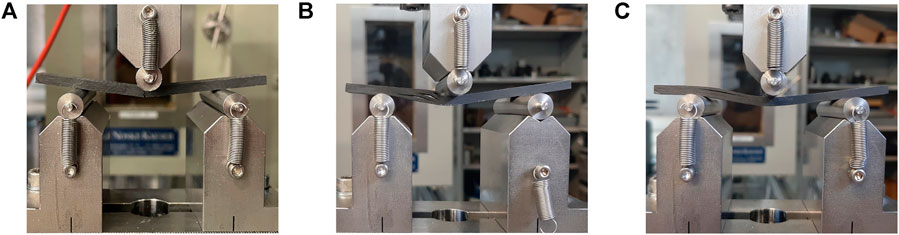
FIGURE 4. Pictures of the side surface of [(0/90)]18 samples during the flexural tests depicting the typical failure of (A) V, (B) D2, and (C) H2 samples.
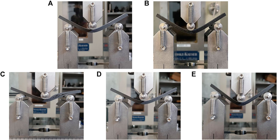
FIGURE 5. Pictures of the [(+45/−45)]18 samples during the flexural tests depicting the typical failure mode of (A) V and (B) VC, (C) and (D) D2, and (E) H2 samples.
Figure 6 shows the average flexural strength and flexural modulus for the V, D2, and H2 specimens with fibers at 0/90°. The average healing efficiency was computed according to Eq. 1, and it resulted to be 72.1% with respect to the flexural modulus and 32.1% with respect to the flexural strength. Using Eq. 2, healing efficiency was 88% and 66%. The healing process is more beneficial to restore the initial flexural modulus rather than the initial flexural strength, and this is probably connected to the fact that when fibers are oriented at 0/90°, they are broken by the impact procedure (morphological characterization is presented in the next section). This indicates that for the test to be meaningful with respect to matrix healing efficiency, minimal fiber damage should be sought.
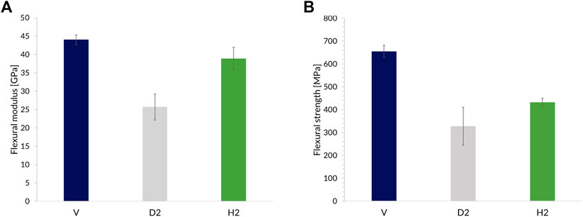
FIGURE 6. (A) The flexural modulus and (B) the flexural strength for V, D2, and H2 [(0/90)]18 specimens.
Figure 7 outlines the average flexural strength and flexural modulus for the V, VC, D2, and H2 specimens with fibers at ±45°. In this case, the average healing efficiency computed according to Eq. 1 resulted in higher values: 92.8% with respect to the flexural modulus and 90.1% with respect to the flexural strength. Using Eq. 2, a 97.5% healing efficiency is obtained for both modulus and strength. The angled fiber orientation, in samples with such a small width, prevented extensive damage to the fibers themselves and favored matrix cracking and delamination, that is, exactly the type of defects the healable matrix of HealTech™ enables to mend. Figures 3B, 7 also highlight that there is no detrimental effect on the mechanical performances due to the healing treatment. In fact, the mending cycle temperature has been chosen to be sufficiently lower than the Tg of HealTech™ T300-TW200-42RW-1250, which is 170°C, so as not to degrade the crosslinking degree.
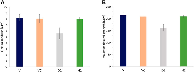
FIGURE 7. (A) The flexural modulus and (B) the flexural strength for V, VC, D2, and H2 [(+45/−45)]18 specimens.
Morphological Characterization
Figure 8 clearly shows the effect of healing, that is, extensive bleeding of the healing agent present in HealTech™. Over the 30 min at 150°C, the healing agent expands and flows partly to fill cracks and delamination and partly bleeds out of the edges of the samples. These two represent the preferential paths for the healing agent, respectively, because of the stresses generated around the area of the cracks that tend to close the cracks themselves or, in the case of the edges, because there are less friction and constraints along this path.
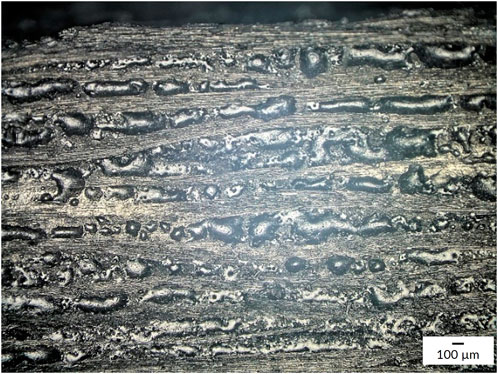
FIGURE 8. Optical microscopy image showing the bleeding of the healing agent on the cross-section of a [(0/90)]18 H2 sample after the healing treatment.
Figures 9 and 10 show optical microscopy images of the cross-section of a [(0/90)]18 sample and a [(+45/−45)]18 D2 sample, respectively. The impact damage process leads to fibers rupture in laminates with fibers oriented at 0/90°, while this is not the case when fibers are oriented at ±45°, a layup which allows a much more extensive fiber deformation before rupture and hence favors damage to the matrix rather than to the fibers. This confirms why much higher healing efficiencies can be attained with such fiber orientation, as HealTech™ healing ability resides in the polymeric resin. However, the fact that fiber rupture or delamination is visible in optical microscopy images of the cross-section of samples entails that the damage area diameter is at least 13 mm (the width of the specimens). Consequently, the reservoirs of the healing agent, which can flow and fill the cracks might be sufficient along the length of the samples but not across the width. The healing agent might preferentially flow out of the sample’s cross-section instead of toward the internal cracks. This might explain the impossibility to demonstrate full healing capabilities even when fibers are not broken. HealTech™ enables to heal cracks up to 100 µm thick (Cohades and Trigueira, 2020), and none of the cracks observed via optical microscopy (Figure 10) exceeds this thickness.
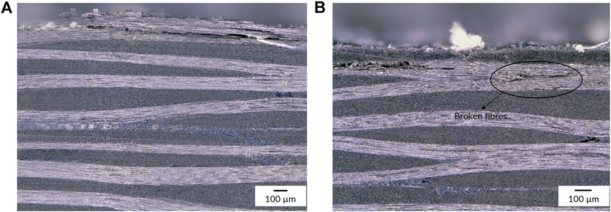
FIGURE 9. Optical microscopy images of the cross-section of D2 [(0/90)]18 samples, clearly displaying some broken fibers, on the top ply (A) and internal ply (B).
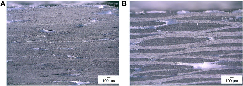
FIGURE 10. (A) Optical microscopy image of the cross-section of a D2 [(+45/−45)]18 sample showing signs of delamination and cracks; (B) a D2 [(+45/−45)]18 sample was cut along fiber direction at the impact location and the obtained cross-section was observed via optical microscopy: No broken fibers can be observed.
Samples size might also be one of the reasons why specimens with fibers oriented at 0/90° display fiber rupture, while this is not the case when fibers are oriented at 45°. Samples with fibers oriented at 0/90° or at ±45° are expected to lead to a more similar impact response if they are wider, as the length of fibers activated in bending during the impact becomes larger for the ±45° case.
Conclusion
A novel characterization method exploiting impact damage and 3-point bending flexural tests successfully demonstrated healing capabilities in carbon-reinforced composites.
Repetitive low-velocity impacts of 6.86 J on [(0/90)]18 laminates could not impart clearly detectable matrix damage and hence a clear decrease in the mechanical performance of the specimens, especially in terms of modulus, which is needed for discrimination between states. As a result, healing efficiency calculated using the difference between healed and damaged states was not representative of the modulus recovery, as the difference between states was in the same order as the standard deviation between samples. For higher impact numbers, samples with a 0/90° fibers orientation proved to be too sensitive to fiber rupture and hence prevented proving the healing capabilities of the polymer matrix. On the other hand, [(+45/−45)]18 specimens displayed matrix cracking and delamination, and no broken fibers were observed via optical microscopy; therefore, matrix healing could be observed. As a consequence, repetitive low-velocity impacts on laminates with a ±45° fiber orientation proved to be an efficient way to introduce a controlled amount of matrix damage and the subsequent flexural tests demonstrated to be a relevant test to quantitatively assess the healing capabilities of the used materials, thus, highlighting the relevance of the whole characterization method. In that case, healing efficiency calculated by both methods is quite similar, as the damage values are different enough from those in the virgin and healed states.
Thus, the presented test method proved to be 1) fast, 2) reliable, 3) requiring the use of a limited amount of material, and 4) representative of early-stage damage of composite FRPs often occurring in the form of delamination or matrix microcracking. As a result, it can be recommended for fast screening of novel healing matrices. As a next step, tests on specimens with a more adapted width might help clarify the influence of samples’ size on the observed damage type and repairability. Unlike CAI, the presented test method enables the evaluation of smaller samples and hence uses less material, but a compromise between these two approaches might be the best solution. Future improvements of the methodology to make it more reproducible might include tests to assess the difference between supported and non-supported impact damage and the influence of the support material on the extent of observed damage; steel might be a good alternative to wood as support material as it is more slowly degraded.
Data Availability Statement
The original contributions presented in the study are included in the article/Supplementary Material; further inquiries can be directed to the corresponding author.
Author Contributions
All authors listed have made a substantial, direct, and intellectual contribution to the work and approved it for publication.
Funding
Open access funding was provided by the École Polytechnique Fédérale de Lausanne.
Conflict of Interest
Authors CS, RT, and AC are employed by CompPair Technologies Ltd.
The remaining author declares that the research was conducted in the absence of any commercial or financial relationships that could be construed as a potential conflict of interest.
Publisher’s Note
All claims expressed in this article are solely those of the authors and do not necessarily represent those of their affiliated organizations, or those of the publisher, the editors, and the reviewers. Any product that may be evaluated in this article, or claim that may be made by its manufacturer, is not guaranteed or endorsed by the publisher.
Acknowledgments
The authors would like to thank Marion Borot and Marion Junger for their technical assistance.
References
Assocompositi, Anev and Futura. (2021) Verso una gestione sostenibile e circolare per il fine vita delle pale eoliche.
Beylergil, B. (2021). Interlaminar Fracture and Crack-Healing Capability of Carbon Fiber/epoxy Composites Toughened with 3D-Printed Poly-ε-Caprolactone Grid Structures. J. Appl. Polym. Sci. 139, 52038. doi:10.1002/app.52038
Bowkett, M., and Thanapalan, K. (2017). Comparative Analysis of Failure Detection Methods of Composites Materials' Systems. Syst. Sci. Control Eng. 5 (1), 168–177. doi:10.1080/21642583.2017.1311240
Cohades, A., Branfoot, C., Rae, S., Bond, I., and Michaud, V. (2018). Progress in Self-Healing Fiber-Reinforced Polymer Composites. Adv. Mat. Interfaces 5 (17), 1800177. doi:10.1002/admi.201800177
Cohades, A., and Michaud, V. (2017a). Damage Recovery after Impact in E-Glass Reinforced Poly(ε-Caprolactone)/epoxy Blends. Compos. Struct. 180, 439–447. doi:10.1016/j.compstruct.2017.08.050
Cohades, A., and Michaud, V. (2017b). Thermal Mending in E-Glass Reinforced Poly(ε-Caprolactone)/epoxy Blends. Compos. Part A Appl. Sci. Manuf. 99, 129–138. doi:10.1016/j.compositesa.2017.04.013
Cohades, A., and Trigueira, R. (2020). Healable Composites to Improve Circularity. Paris: JEC Composites Magazine, 41–43. (N°136 September-October).
Hia, I. L., Vahedi, V., and Pasbakhsh, P. (2016). Self-Healing Polymer Composites: Prospects, Challenges, and Applications. Polym. Rev. 56 (2), 225–261. doi:10.1080/15583724.2015.1106555
Hostettler, N., Michaud, V., and Cohades, A. (2019). Healable Composites and Their Performance Through Mechanical and Durability Testing. JEC Composites Magazine, 58–61.
Jony, B., Mulani, S. B., and Roy, S. (2022). Interlaminar Shear Fracture Healing of Thermoset CFRP Composite Using Multiphase Thermoplastic Healing Agents. Compos. Struct. 279, 114807. doi:10.1016/j.compstruct.2021.114807
Kamble, M., Picu, C., and Koratkar, N. (2021). ‘Vitrimer Composites for Rotorcraft Components’, 77th Annual Vertical Flight Society Forum And Technology Display, FORUM 2021: The Future Of Vertical Flight, 1–5.
Kamble, M., Vashisth, A., Yang, H., Pranompont, S., Picu, C. R., Wang, D., et al. (2022). Reversing Fatigue in Carbon-Fiber Reinforced Vitrimer Composites. Carbon 187, 108–114. doi:10.1016/j.carbon.2021.10.078
Kanu, N. J., Gupta, E., Vates, U. K., and Singh, G. K. (2019). Self-healing Composites: A State-Of-The-Art Review. Compos. Part A Appl. Sci. Manuf. 121, 474–486. doi:10.1016/j.compositesa.2019.04.012
Katnam, K. B., Da Silva, L. F. M., and Young, T. M. (2013). Bonded Repair of Composite Aircraft Structures: A Review of Scientific Challenges and Opportunities. Prog. Aerosp. Sci. 61, 26–42. doi:10.1016/j.paerosci.2013.03.003
Kling, S., and Czigány, T. (2014). Damage Detection and Self-Repair in Hollow Glass Fiber Fabric-Reinforced Epoxy Composites via Fiber Filling. Compos. Sci. Technol. 99, 82–88. doi:10.1016/j.compscitech.2014.05.020
Lucas, S. S., von Tapavicza, M., Schmidt, A. M., Bertling, J., and Nellesen, A. (2016). Study of Quantification Methods in Self-Healing Ceramics, Polymers and Concrete: A Route towards Standardization. J. Intelligent Material Syst. Struct. 27 (19), 2577–2598. doi:10.1177/1045389x16641205
Luterbacher, R., Trask, R. S., and Bond, I. P. (2015). Static and Fatigue Tensile Properties of Cross-Ply Laminates Containing Vascules for Self-Healing Applications. Smart Mater. Struct. 25 (1), 15003. doi:10.1088/0964-1726/25/1/015003
Manfredi, E., Cohades, A., Richard, I., and Michaud, V. (2015). Assessment of Solvent Capsule-Based Healing for Woven E-Glass Fibre-Reinforced Polymers. Smart Mat. Struct. 24 (1), 015019. doi:10.1088/0964-1726/24/1/015019
Meure, S., Wu, D. Y., and Furman, S. (2009). Polyethylene-co-methacrylic Acid Healing Agents for Mendable Epoxy Resins. Acta Mater. 57 (14), 4312–4320. doi:10.1016/j.actamat.2009.05.032
Pang, J., and Bond, I. (2005). 'Bleeding Composites'-Damage Detection and Self-Repair Using a Biomimetic Approach. Compos. Part A Appl. Sci. Manuf. 36 (2), 183–188. doi:10.1016/s1359-835x(04)00166-6
Park, J. S., Kim, H. S., and Thomas Hahn, H. (2009). Healing Behavior of a Matrix Crack on a Carbon Fiber/mendomer Composite. Compos. Sci. Technol. 69 (7–8), 1082–1087. doi:10.1016/j.compscitech.2009.01.031
Patrick, J. F., Hart, K. R., Krull, B. P., Diesendruck, C. E., Moore, J. S., White, S. R., et al. (2014). Continuous Self-Healing Life Cycle in Vascularized Structural Composites. Adv. Mat. 26 (25), 4302–4308. doi:10.1002/adma.201400248
Si, H., Zhou, L., Wu, Y., Song, L., Kang, M., Zhao, X., et al. (2020). Rapidly Reprocessable, Degradable Epoxy Vitrimer and Recyclable Carbon Fiber Reinforced Thermoset Composites Relied on High Contents of Exchangeable Aromatic Disulfide Crosslinks. Compos. Part B Eng. 199, 108278. doi:10.1016/j.compositesb.2020.108278
Sordo, F., and Michaud, V. (2016). Processing and Damage Recovery of Intrinsic Self-Healing Glass Fiber Reinforced Composites. Smart Mat. Struct. 25 (8), 084012. doi:10.1088/0964-1726/25/8/084012
Suschem (2018). Polymer Composites Circularity. 21. Available at: https://baxcompany.com/wp-content/uploads/2018/11/Suschem_composites_circularity_pages.pdf.
Tesoro, G. C., and Sastri, V. (1990). Reversible Crosslinking in Epoxy Resins. I. Feasibility Studies. J. Appl. Polym. Sci. 39 (7), 1425–1437. doi:10.1002/app.1990.070390702
Trask, R. S., and Bond, I. P. (2006). Biomimetic Self-Healing of Advanced Composite Structures Using Hollow Glass Fibres. Smart Mat. Struct. 15 (3), 704–710. doi:10.1088/0964-1726/15/3/005
Urdl, K., Kandelbauer, A., Kern, W., Müller, U., Thebault, M., and Zikulnig-Rusch, E. (2017). Self-healing of Densely Crosslinked Thermoset Polymers-A Critical Review. Prog. Org. Coatings 104, 232–249. doi:10.1016/j.porgcoat.2016.11.010
Véronique, M., and Cohades Amael, H. N. (2019). Healable Composites and Their Performance through Mechanical and Durability Testing.
Williams, G. J., Bond, I. P., and Trask, R. S. (2009). Compression after Impact Assessment of Self-Healing CFRP. Compos. Part A Appl. Sci. Manuf. 40 (9), 1399–1406. doi:10.1016/j.compositesa.2008.05.021
Williams, G., Trask, R., and Bond, I. (2007). A Self-Healing Carbon Fibre Reinforced Polymer for Aerospace Applications. Compos. Part A Appl. Sci. Manuf. 38 (6), 1525–1532. doi:10.1016/j.compositesa.2007.01.013
Keywords: self-healing, circular economy, composites, polymers, mechanical properties, composite healing, healing characterization
Citation: Scazzoli C, Trigueira R, Cohades A and Michaud V (2022) A Novel Method to Quantify Self-Healing Capabilities of Fiber-Reinforced Polymers. Front. Mater. 9:932287. doi: 10.3389/fmats.2022.932287
Received: 29 April 2022; Accepted: 24 June 2022;
Published: 18 July 2022.
Edited by:
Antonio Mattia Grande, Politecnico di Milano, ItalyReviewed by:
Panagiota Polydoropoulou, University of Patras, GreeceSyafiqah Nur Azrie Safri, Universiti Tun Hussein Onn Malaysia, Malaysia
Copyright © 2022 Scazzoli, Trigueira, Cohades and Michaud. This is an open-access article distributed under the terms of the Creative Commons Attribution License (CC BY). The use, distribution or reproduction in other forums is permitted, provided the original author(s) and the copyright owner(s) are credited and that the original publication in this journal is cited, in accordance with accepted academic practice. No use, distribution or reproduction is permitted which does not comply with these terms.
*Correspondence: Cecilia Scazzoli, Y2VjaWxpYUBjb21wcGFpci5jaA==