 Changjie Xu1,2,3
 Zhaorui Lin1,2
 Yalong Jiang1,2*Yufeng Shi1,2Xiaozhen Fan4Zheng Xiong1,2Yangfeng Liu1,2
- 1Institute of Geotechnical Engineering, School of Civil Engineering and Architecture, East China Jiaotong University, Nanchang, China
- 2Jiangxi Key Laboratory of Infrastructure Safety and Control in Geotechnical Engineering, East China Jiaotong University, Nanchang, China
- 3State Key Laboratory of Performance MonitoringProtecting of Rail Transit Infrastructure, East China Jiaotong University, Nanchang, China
- 4Zhejiang University City College, Hangzhou, China
Abstract: This research describes the evolution of the spatial effects of foundation pits considering internal support and external loads. Based on the existing concept of “plane strain ratio”, the term “plane strain ratio considering maximum surface settlement” is proposed to characterize the spatial effects of an asymmetric foundation pit. A series of finite element model calculations were carried out using the Nanchang Aixi Lake foundation pit, including 1) the calculation of simulated actual conditions, 2) the calculation of simulated full symmetric load, and 3) the calculation of simulated asymmetric load. The results indicate that for the symmetric condition at 20 kPa and below, the spatial effect range increases as the load increases. For the symmetric condition above 20 kPa, the load has a negligible impact on the spatial effect range. On the side with a larger load under asymmetric loading conditions, the spatial effect of the working condition below 30 kPa is smaller than the corresponding symmetric load. On the side with a smaller load, the spatial effect of the working condition above 80 kPa increases compared with that of the corresponding symmetrical load. Given and verified are the modified fitting equations that take into account the influence range of spatial effect on both sides of the foundation pit under symmetrical and asymmetrical loads.
1 Introduction
Due to the construction and development of cities, the limited urban space and heavy traffic make the environment surrounding deep foundation pits exceedingly complicated (Zhang J. et al., 2018). Growing concern exists regarding the impact of deep foundation pit excavation on the surrounding environment and neighboring existing buildings (Chang et al., 2013; Xu et al., 2013; Mangushev et al., 2016; Xu et al., 2016; Zhang X. et al., 2018; Luo et al., 2018; Zeng et al., 2018; Sun et al., 2019; Bai et al., 2020; Fan et al., 2021). Figure 1 depicts a typical scenario in which the surrounding environment interacts with the foundation pit and generates a disaster. The influence of the surrounding environment on the foundation pit is insufficiently considered, and the deformation of the retaining structure and ground cannot be assessed adequately. Damage to surrounding structures and casualties may result from the excessive movement of retaining structures and earth (Shouhua et al., 2019). Therefore, engineers must give comprehensive consideration to the influence of the surrounding environment on deep foundation pits.
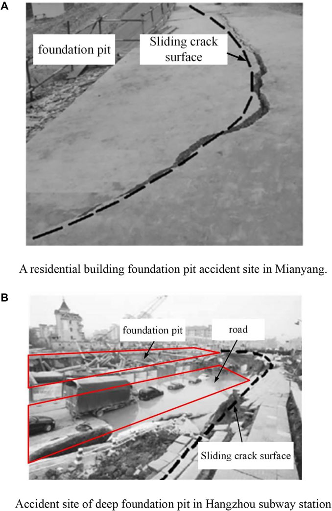
FIGURE 1. Typical example of the influence of a foundation pit on its interaction with the surrounding environment (Li et al., 2014). (A) A residential building foundation pit accident site in Mianyang. (B) Accident site of deep foundation pit in Hangzhou subway station..
The surrounding environment affects the excavation and deformation of deep foundation pits subjected to a variety type of loads. These loads usually emerge on both sides of the pit in an asymmetrical manner, which can bring uncertainty to the deformation of the pit support. In a foundation pit with an internally braced support system, the effect of the asymmetrical state is particularly pronounced. Due to the existence of internal bracing, which can lead to complex force transfer issues, the support structures on both sides of the foundation pit may be affected. The available engineering empirical data indicate that asymmetric loads can lead to inconsistent foundation pit deformation on both sides. In the case of small load differences or strict displacement control by the support design, the deformation patterns of the support structures on all sides may be similar, but the amplitudes will vary (Yao and Zhang, 2011; Guo et al., 2019). More frequently than not, asymmetric loads can create a “push-back displacement” toward the exterior of the foundation pit on the side with the smaller load (Xu et al., 2013; Shouhua et al., 2019; Ou et al., 2020; Wang et al., 2021). This means that the top of the support structure on that side may show a reverse displacement towards the outside of the pit. Existing foundation design theories are based on a single side, which cannot logically account for such a condition. Some scholars have also attempted to undertake theoretical research (Xu et al., 2013; Liu et al., 2019), but due to the unique peculiarities of the working condition, these studies have always lacked practical relevance.
With the growth of numerical computation methods and computer technology, numerical simulation has been widely used as a common method in areas that are difficult to be explained by theory. The design of an asymmetric pit is a typical example. Some scholars have utilized numerical modeling techniques to optimize the design of each side in asymmetric pits. On the side with greater loads, especially in projects with special requirements for displacement control, it is required to optimize the deformation situation based on the results of numerical simulations to meet the requirements (Liu et al., 2019; Ou et al., 2020). On the smaller loaded side, it is possible to reduce the reinforcement of the supporting structure appropriately (Lin et al., 2010). This prevents waste because the design is based on the least desirable side. Nevertheless, these optimization efforts are constrained by existing foundation pit design theories. They continue to rely on the plane strain theory, which reduces the foundation pit to 2D for optimization purposes (Li et al., 2021; Chen et al., 2022). The support system of the foundation pit is a 3D complex system with length, width, and height. In the case that the length-to-width ratio and length-to-depth ratio are insufficient, this will inevitably bring a significant mistake. Using 3D numerical simulation approaches, some of the most intricate engineering research has avoided these errors (Guo et al., 2019; Shouhua et al., 2019; Wang et al., 2021). These works are extremely innovative, however, due to the complexity of the studied works, no general experience and guiding principles have been synthesized. The 3D numerical simulations were performed without analyzing and summarizing the deformation of the support structure at the spatial level, and the value of these works was not fully exploited.
To clarify the impact of the foundation pit on the surrounding environment, it is vital to comprehend the spatial deformation of the foundation support system. Past accidents involving foundation pits that have occurred and resulted in damage patterns at the spatial level, demonstrating the necessity of these studies (e.g., Figure 1). The work done by (Chang-Yu et al., 1996; Chang-Yu and Bor-Yuan, 1998; Chang-Yu et al., 2000) is very classical and valuable. They used a 3D nonlinear finite element method based on computer programming techniques to simulate the excavation process of a foundation pit. The concept of “plane strain ratio” (PSR) was initially proposed to quantitatively measure the development of the spatial effect of the foundation pit, and the parametric analysis determined the relationship equation between the 2D calculation results and the 3D calculation results. On the basis of their research, other 3D numerical simulation-based studies with varying focuses were conducted. For instance, (Roboski and Finno, 2006; Finno et al., 2007; Tanner Blackburn and Finno, 2007), established a database covering 150 finite element models and summarized empirical equations between the geometry, the stiffness of the lateral support system, and the safety factor of the footing uplift and the PSR. In addition, the spatial effect cases of different support forms and the spatial distribution of earth pressure (Li and Liang, 2011; Chenghua et al., 2018; Bai et al., 2019; Bai et al., 2020; Bai et al., 2021; Chen and Mo, 2022; Chen and Zhang, 2022) have been investigated. In the majority of studies of spatial effects, plasticity theory has been employed at the theoretical level. These projects include research on sandy soil (Yang et al., 1998) and clay (Mingfeng et al., 2011) foundation pits. In these works, the scope of spatial effects and theoretical calculation methods have been developed. Unfortunately, no research has been conducted on the topic of load in the spatial effect of foundation pits. In addition, due to the limitations of plasticity theory, the application of these theoretical calculation approaches to asymmetric pits is further restricted.
The objective of this paper is to establish a connection between asymmetric loads and the spatial effects of foundation pits. To achieve this purpose, the “plane strain ratio considering the maximum surface settlement” is introduced to quantitatively evaluate the evolution of spatial effects. This is illustrated by the Aixi Lake Tunnel project in Nanchang, Jiangxi, China, where the engineering phenomena “pit within a pit” exists. Firstly, 3D simulation calculations are performed under simulated field conditions and compared with actual monitoring data to validate the accuracy of the parameter selection. Then the development of the spatial effect of the foundation pit under symmetric loads is investigated only for the support of the foundation’s outer pit. By fitting data derived from finite element calculations, an empirical formula for the influence range of pit spatial effects under symmetric loading considering internal bracing is obtained. Then, the finite element calculations are run for the calculation cases under different load differences and asymmetrical load effects, and the corrections are made again. Finally, the formula calculation results are compared with simulation findings of spatial effects under alternative load conditions to verify the effectiveness of the equation correction.
2 Site characterization
2.1 Project background
The deep foundation pit described in this paper is located in Nanchang, Jiangxi, China, and was excavated for the common construction of the highway crossing Aixi Lake and Nanchang Metro Line 3. A diaphragm wall and three internal supports comprise the outer pit support system. The first internal support is made of concrete, while the second and third internal supports are made of steel. The inner pit support system is comprised of row piles and two internal supports, the first of which is concrete support and the second of which is steel support. Both sides of the pit’s cofferdam provide a specific load to the support structure.
The 120-meter-long section of the pit from K1+220 to K1+340 in the middle of the lake was used for analysis in this research. To measure the horizontal displacement of the diaphragm wall, the slanting tubes were placed on the supporting structure in the center of the foundation pit. Figure 2A depicts the plan layout of the sampled section and the location of the testing instruments. Figure 2B outlines the typical section of the foundation pit support structure.
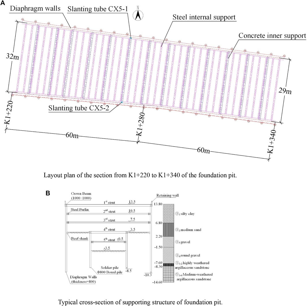
FIGURE 2. Analysis of selected pit project profile. (A) Layout plan of the section from K1+220 to K1+340 of the foundation pit. (B) Typical cross-section of supporting structure of foundation pit.
2.2 Soil profile and parameters
Figure 2B depicts the soil profiles acquired from the geological survey. The main soil layers from the ground to the considered depth are silty clay, medium sand, gravel, round gravel, and argillaceous sandstone. The thickness of each layer can be calculated based on the elevation shown in the soil profile in Figure 2B. The soil parameters for each layer, as determined by field and laboratory experiments, are summarized in Table 1.
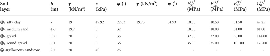
TABLE 1. Soil parameters.
3 Standard and assumption
3.1 Criteria for determining spatial effects in the asymmetrical case
In the past, most of the spatial effect studies were undertaken for symmetric foundation pit excavation. Some utilize the “spatial effect coefficient” (Yang et al., 1998; Mingfeng et al., 2011) while others utilize the “plane strain ratio” (PSR) (Chang-Yu et al., 1996; Finno et al., 2007) to describe the extent of the spatial effect. These coefficients are frequently employed to analyze the maximum horizontal displacement of the supporting structure or the amount of the earth pressure. Under the influence of symmetric load, such a discriminative approach is viable. Due to the fact that, under the influence of symmetric excavation, the maximum point of horizontal displacement of the support structure on both sides of the foundation pit is approximately equal, and the action of earth pressure is likewise close. However, under the action of asymmetrical loads, the maximum horizontal displacement point of the support structure on either side of the pit varies. The variation in the deformation of the retaining wall also affects the magnitude and distribution of earth pressure. Therefore, it is necessary to propose a coefficient that can effectively discriminate the development of the spatial effect of the support structure on both sides of the pit when subjected to asymmetrical loads.
The surface soil deformation is a key indicator to focus on in addition to earth pressure and wall displacement (Cui et al., 2020). Heish et al. (Pio-Go and Chang-Yu, 1998) offered two possible settlement situations for the settlement of the soil behind the retaining wall: triangular and notched. For these two settlement scenarios, the maximum surface settlement behind the wall occurs at the back of the wall and at 0.5 times the excavation depth, respectively. The position of maximum settlement happens exclusively in relation to the dislocation pattern of the retaining wall. This discrimination method has been frequently utilized due to its simplicity and accuracy.
The original concept of PSR is defined as “maximum wall displacement as the ratio of the maximum wall displacement of a section to the maximum wall displacement of the section under plane strain conditions” (Chang-Yu et al., 1996). In this paper, the “plane strain ratio considering the maximum surface settlement” (PSRS) is proposed as a criterion for identifying the spatial effect development in an asymmetrical foundation pit. PSRS is the ratio of the surface settlement at any point on a line parallel to the pit boundary at the theoretical maximum settlement behind the retaining wall to the maximum surface settlement at that point. The first time the PSRS value hits 0.95 from either side of the foundation pit is considered the boundary between the plane strain zone and the spatial effect zone at that end of the foundation pit. This division approach successfully covers the plane strain area and is easy to implement.
3.2 Simplifications and assumptions in theoretical calculations
To simplify the calculation, the equation fitting and theoretical calculations in this work make the following assumptions and simplifications.
1) The concept of equal-substituted internal friction angle is introduced, the silty clay layer is equal-substituted as a cohesionless soil, and the calculation is performed using the equal-substitution method with equal shear strength of the soil. The specific calculation equation is as follows:
where
2) It is assumed that the calculation area is filled with a single homogeneous soil layer. For the soil layers discussed above, the sum-of-layers approach is used to homogenize them. The exact expression is as follows:
where
The parameters of the soil layer after equal substitution and homogenization are shown in Table 1.
4 Simulation and discussion under symmetric load conditions
4.1 Model establishment
In this paper, plaxis3D is used to simulate the symmetric and asymmetric excavation of the foundation pit in 3D. Figure 3 depicts the 3D model of the deep foundation pit, the mesh division, and the model size. The model size accounts for the avoidance of boundary effects, and the principle of increasing the model size has no effect on the response of the pit excavation.
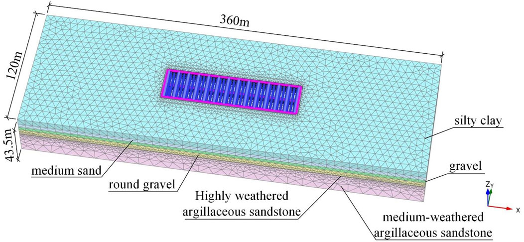
FIGURE 3. Finite element model.
The soils in the model consist of silty clay, medium sand, gravel, round gravel, highly weathered argillaceous sandstone, and medium-weathered argillaceous sandstone. To accurately describe the force deformation during the excavation of the foundation pit, the Hardening Soil Small (HSS) model is used to simulate the intrinsic relationships of the silty clay, medium sand, gravel, and round gravel layers. The HSS model introduces minor strain properties based on the Hardening Soil model, which can accurately simulate the deformation trend of the support structure and soil during the excavation of the foundation pit but has the disadvantage that the parameters are difficult to be determined. Through lab tests, the values of soil parameters are determined by indoor experiments. Table 1 displays the values. Using the Mohr-Coulomb model, layers of highly weathered argillaceous sandstone and medium-weathered argillaceous sandstone are reproduced. The support structure in the project is simulated by the structure unit, the support in the pit is simulated by the point-to-point anchor, the diaphragm wall and the row pile support are simulated by the plate unit, and the interaction between the soil and the structure is simulated by the interface unit.
4.2 Simulation of excavation under symmetric load
As illustrated in Table 2, the excavation of the foundation pit was simulated. In the first stage, the ground stress was initialized according to the principle of homogeneous, continuous, and isotropic soil layers, and the requisite loads were applied. Prior to the first excavation stage, the displacements and minor strains of the model were reset. The simulation procedures were then followed.
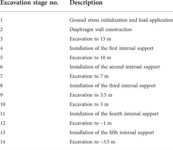
TABLE 2. Stages of excavation in FEM analysis.
In the calculation of the model parameter check, a 20 kPa asymmetric uniform load is applied on both sides of the pit. The uniform load is applied at a distance of 1 m from the foundation boundary, and the load width is 5m, spanning the entire length of the long side of the foundation pit to imitate the load of the cofferdam on both sides of the foundation pit for the foundation pit enclosure structure at the engineering site. All steps in Table 4 are replicated during the calibration computation.
In the study examining the spatial effects of load, the full load behind the retaining wall was used to determine the typicality of the load factors. From Eq.
The calculation suggests that the full pile load length outside the foundation pit is approximately 13.32 m, x is the load length outside the foundation pit, H is the length of the support pile, and φ is the angle of internal friction in the equation. In the subsequent load calculation, the load outside the foundation pit was assumed to extend 15 m from the foundation pit’s perimeter, spanning the entire length of the foundation pit’s long side. The load is measured from 0 to 100 kPa in 10 kPa increments on both sides of the foundation pit and applied symmetrically. In the examination of spatial effects, only the excavation to the bottom of the outer pit is studied, and the effects generated by the piles in the inner pit row are excluded in the simulation. In the subsequent simulations under symmetrical and asymmetrical loads, therefore, just the first nine simulation steps are executed.
4.3 Analysis of FEM results for symmetric load conditions
4.3.1 Analysis of FEM analysis results simulating the realistic condition
The focus must be placed on the horizontal deformation of the support structure in the actual project. When the foundation pit in the calculation example is excavated to the bottom of the inner pit, Figure 4 depicts the horizontal deformation of the outer pit’s ground connection wall. In the depth direction, the horizontal displacement of the diaphragm wall is minimal at the top and bottom and abundant in the middle, indicating a “bloated belly” deformation trend. The maximum depth of horizontal displacement is close to the base of the outer pit. Figure 5 depicts a comparison between the monitoring data at CX5 and the maximum wall displacement derived from FEM. The deformation trends and maximum displacements of both are comparable. The peak displacements of the monitoring data looked to be somewhat greater than the FEM results. The realistic force condition of the foundation pit is complex, and the FEM simplification resulted in a certain amount of mistakes. The similar deformation trends and peak displacements of the two indicate that the model parameter selection was fair.
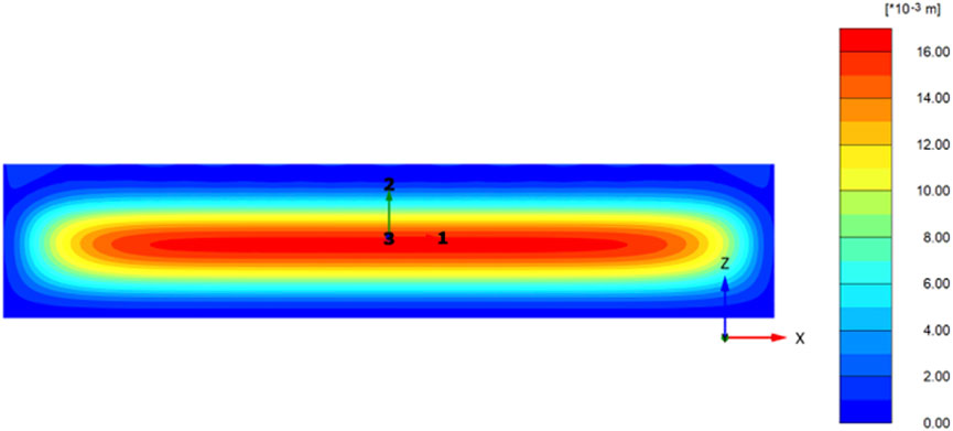
FIGURE 4. Horizontal displacement cloud plot of the external pit diaphragm wall.
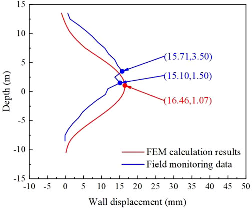
FIGURE 5. Comparison of monitoring data and FEM calculation of horizontal displacement of the diaphragm wall.
The measured data and numerical calculations result in the deformation of the ground connection wall, which shows the deformation tendency of the “bloated belly” and is consistent with the description of the “concave settlement profile” soil settlement model behind the wall in the literature. Therefore, the PSRS parameter values were determined using the surface settlement value at an excavation depth of 0.5 times behind the retaining wall.
4.3.2 Carrying out spatial effects under full symmetric load
Figure 6 depicts the maximum settlement outside the foundation pit along the diaphragm wall direction for the 11 computed symmetry conditions. The maximum settlement values outside the foundation pit exhibit a distinct spatial influence. Near the end, the surface settlement values are much less than those in the middle. The surface settlement values stabilize after a given distance from the terminus. As depicted in Figure 6A, the plane strain zone in the center of the foundation pit displays a “sawtooth” deformation pattern under the minor load. The location of the minor deformation and the first internal support of the foundation pit coincide substantially. Under conditions of low load, the internal support can effectively control the horizontal displacement of the diaphragm wall. In the zone with “sawtooth” deformation, the PSRS = 0.95 criterion can still cover the deformation in the center of the foundation pit, indicating that this criterion is reliable in delineating the plane strain zone and the zone affected by spatial effects. Under working conditions with a load of more than 20 kPa, the deformation of the plane strain zone exhibits a smooth curve, and the deformation in the middle part is close.
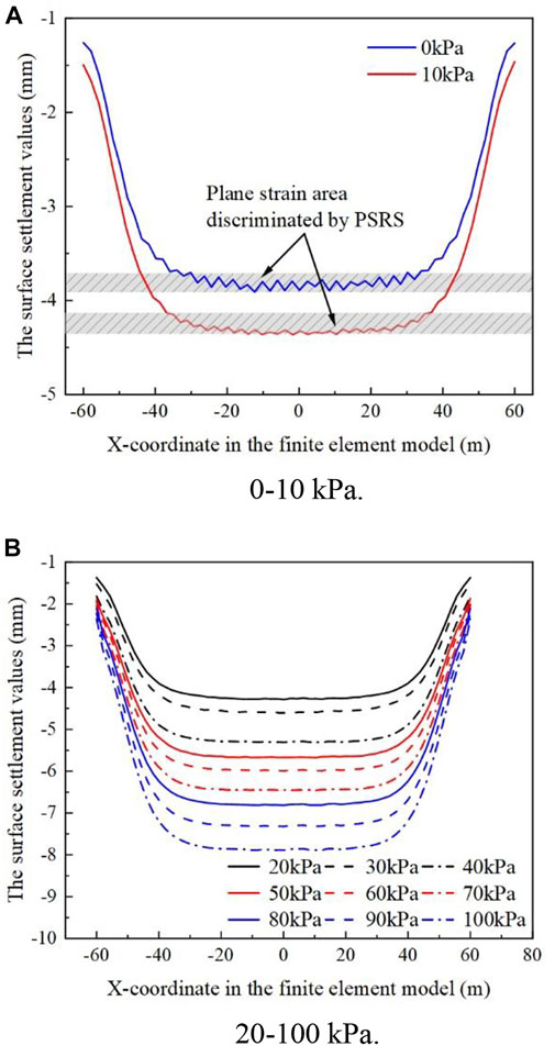
FIGURE 6. Development of spatial effect of the foundation pit under the symmetrical load of 0–100 kPa. (A) 0–10 kPa. (B) 20–100 kPa.
Table 3 summarizes the influence range of spatial effects under various operating situations. In the case of no-load action outside the foundation pit, the spatial effect influence range of the foundation pit is greatest. With a rise in the appropriate load value, the spatial effect influence range tends to diminish. When the load exceeds a particular threshold and the load outside the pit is increased, the spatial effect influence range hardly changes. The spatial effect influence range swings between 23.01 and 23.84 m for the eight working conditions with a load value outside the pit between 30 and 100 kPa, and there is no discernible rise or fall. After the load reaches a particular magnitude, the soil of the foundation pit wall may reach a state of equilibrium.

TABLE 3. Range of spatial effects under symmetric conditions.
4.4 Correction of the spatial effect range under symmetric load
4.4.1 Equation correction
(Yang et al., 1998) suggested the following equation for estimating the influence range of spatial effects using the theory of plasticity ceiling:
where b is the spatial effect influence range and βcr is the critical rupture angle of the soil. βcr is obtained from the trial calculation of Eq. 6.
Where γ is the weight of the soil, and δ is the wall-soil friction angle. It can be found that βcr = 53.4° in the calculation of this paper. Substituting the soil parameters and critical rupture angle into Eq. 5, we can determine that b = 18.63 m for this case. This computation result differs significantly from the one provided in Table 3. There are two primary causes for this problem. The first reason is that Eq. 5 does not account for the case of load, and the second reason is that Eq. 5 does not account for the restraining effect of the internal support of the foundation pit on the displacement of the retaining structure. Therefore, the coefficient k1 considering the loads on both sides of the foundation pit is first introduced, and the first fitting modification to Eq. 5 is made so that it satisfies the requirements for application in inner braced support systems considering the following loads.
where P is the load on both sides of the pit.
Considering the calculation results of Table 3, the value of k1 in Eq. 7 is fitted as shown in Figure 7A.
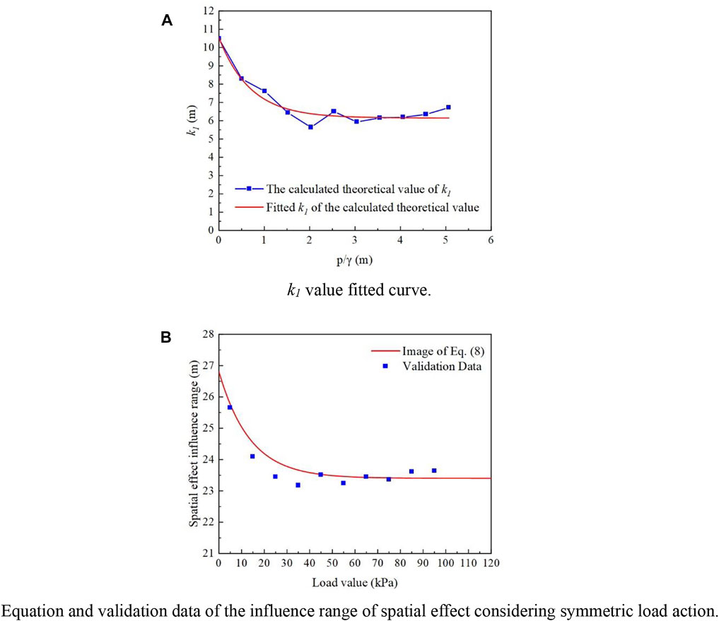
FIGURE 7. Symmetric case fitted results and validation data. (A) k1 value fitted curve. (B) Equation and validation data of the influence range of spatial effect considering symmetric load action.
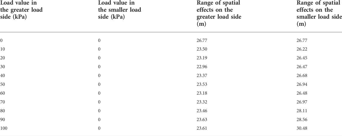
TABLE 4. Range of spatial effects on both sides of the foundation pit under asymmetric loads.
The spatial effect range of the internally braced support system considering the external load of the foundation pit can be determined using the formula for fitting analysis.
which
4.4.2 Equation validation
After correcting the resulting Eq. 8, the image is plotted according to the curve in Figure 7B. Take the load value outside the foundation pit 5–95 kPa, every 10 kPa as a kind of condition for calculation, and get 10 sets of validation data, as illustrated in Figure 7B. The difference between the fitted equation calculation results and the trend of the validation data is less than 0.5 m. The calculated validity of the fitted equation can be observed.
5 Simulation and discussion under asymmetric conditions
5.1 Simulation of excavation under asymmetric loads
The condition with 0 kPa on the smaller side of an asymmetric load is simulated first. The greater load side is measured from 0 to 100 kPa in 10 kPa increments. The conditions of 20 kPa and 40 kPa on the side with the smaller load are subsequently compared.
5.2 Analysis of FEM results under asymmetric loads
Figure 8 illustrates the vertical deformation in the plane strain zone at 0:20 kPa. The maximum ground surface settlement behind the diaphragm wall is between 5 and 10 m on both sides of the higher and lower loads. The proposed “concave settlement profile” model accurately describes the surface settlement in both cases. It can be demonstrated that the PSRS value is dependable for describing the development of spatial effects on both sides of the asymmetric foundation pit and that the position of its value does not change much when asymmetric pressure occurs.
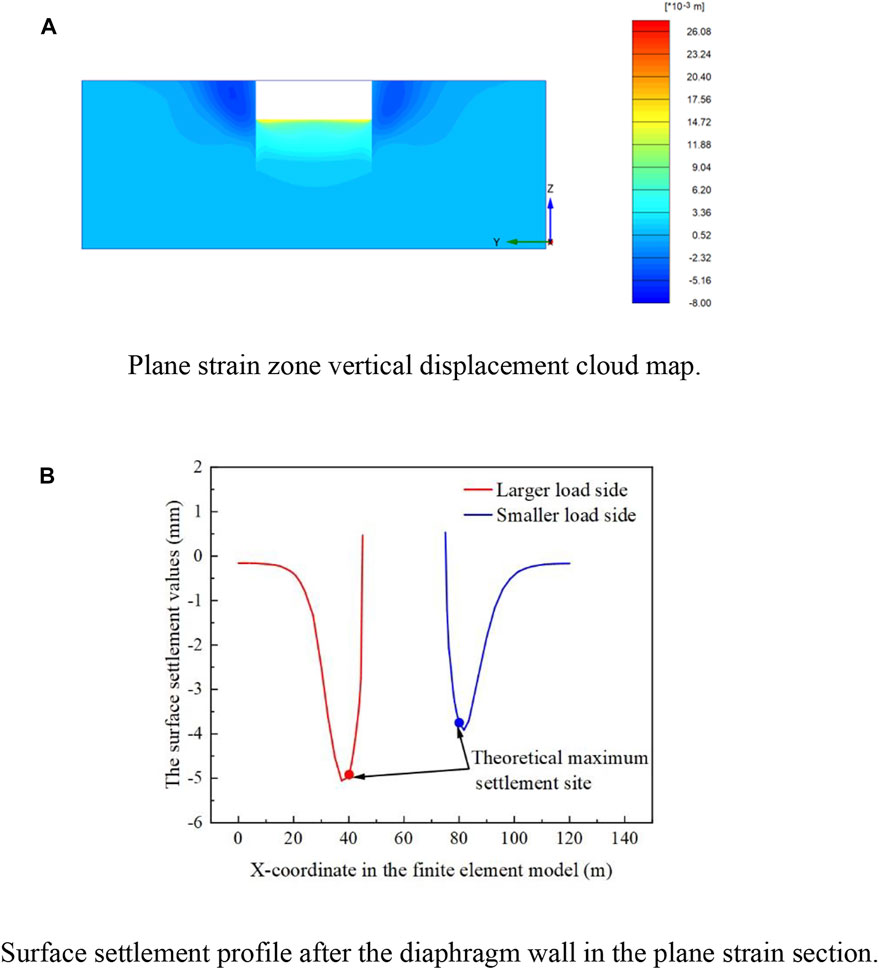
FIGURE 8. Vertical deformation under 0:20 kPa condition. (A) Plane strain zone vertical displacement cloud map. (B) Surface settlement profile after the diaphragm wall in the plane strain section.
Table 4 and Figure 9 show the range at which the spatial effects on the greater side of the foundation pit load and the smaller side of the load under the asymmetric load of the deflection condition. Comparing the influence range of the side with greater loads to that of the side with smaller loads under the same working conditions reveals that the influence range of the side with smaller loads is significantly greater. The development of spatial effects on one side of the foundation pit is determined mostly by the loads on that side.
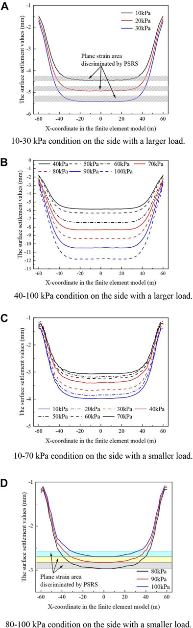
FIGURE 9. Spatial effect influences range when the load is 0 kPa on the smaller side. (A) 10–30 kPa condition on the side with a larger load. (B) 40–100 kPa condition on the side with a larger load. (C) 10–70 kPa condition on the side with a smaller load. (D) 80–100 kPa condition on the side with a smaller load.
With the application of bias pressure on both sides of the foundation pit, the spatial effect influence range sharply decreases on the greater load side of the foundation pit, reaching an interval between 22.96 and 23.63 m. For the ten conditions with asymmetrically applied loads, the spatial effect influence range on the side with greater loads fluctuates in the interval of 22.96–23.63 m. Comparing with the symmetric load conditions corresponding to the load size in Table 3, the spatial effect influence range is significantly reduced for the three conditions with smaller load values. In addition, the difference between the two spatial impacts in the seven situations ranging from 40–100 kpa is negligible. To study the cause of this phenomenon, the symmetric 20 kPa load condition and the asymmetric 0:20 kPa load condition were selected for comparison. The diaphragm wall on the bias side of the latter condition is likewise selected for the study. The horizontal displacement value of the diaphragm wall in the symmetric condition (8 mm) is less than the horizontal displacement value of the ground connection wall of the same size in the asymmetric condition (8.5 mm). This situation may occur when the load is not applied to the smaller side of the load, hence preventing the internal support from maximizing the constraining impact of the deformation on the larger side of the load. This situation makes the soil of the foundation pit wall on the side with the greater load to achieve the limit equilibrium more rapidly, which influences the development of the spatial effects. Therefore, Eq. 7 must be corrected by utilizing the greater side value of the load.
On the side of the foundation pit with less load, the spatial effect of the seven conditions with less load has a comparable influence range. In the three operating circumstances when the load is increased, the spatial effect range expands dramatically. This could be owing to the higher value of bias pressure on both sides of the foundation pit, as well as the fact that the soil of the foundation pit wall on the side with the lighter load is not in ultimate equilibrium. As depicted in Figure 9, the deformation on the side with a smaller load reduces as the load difference increases. The constantly shrinking displacement generates a significant difference between the state of the soil when the load difference is minimal. If the bias rises further, it is expected that the side with less load will approach zero displacements. The support structure may even experience a “push-back displacement” toward the outside of the foundation pit, and the soil behind the wall may cause an elevation. It can be seen that on the side with a smaller load, the load difference between the two sides of the foundation pit is an essential determining factor in addition to the load on that side. It can be seen that the cause for the difference in the influence range of the spatial effect of the foundation pit on the side with the greater load and the side with the smaller load is relatively distinct.
Therefore, the corrections for the side with the bigger load and the side with the smaller load must be evaluated individually in the ensuing work.
5.3 Correction of the spatial effect range under asymmetric loads
In the asymmetric state, the factors that lead to the soil of the foundation wall being in non-limiting equilibrium are distinct. To resolve the dilemma, the spatial consequences on both sides of the asymmetric foundation pit are evaluated independently. On the side of the larger load, introduce the coefficient k2 that considers the load on the larger side of the load, and obtain the following equation for the spatial effect range of the larger side of the load:
On the smaller side of the load, the coefficient k3 that considers the difference of the load on both sides of the foundation pit is introduced, and the following equation is derived for the spatial effect influence range on the smaller side of the load.
Where P1 is the load value on the larger side of the load, P2 is the load value on the smaller side of the load, and Δ is the absolute value of the load difference between the two sides of the foundation pit.
5.3.1 Greater load side equation correction
According to the previous analysis, Eq. 8 is again corrected with the ratio of the load value on that side to the soil weight as the independent variable on the side with greater loads. The form of the correction equation is shown in Eq. 9. Considering the calculation results of Table 4 together, the value of k2 taken in Eq. 9 is fitted, as illustrated in Figure 10A.
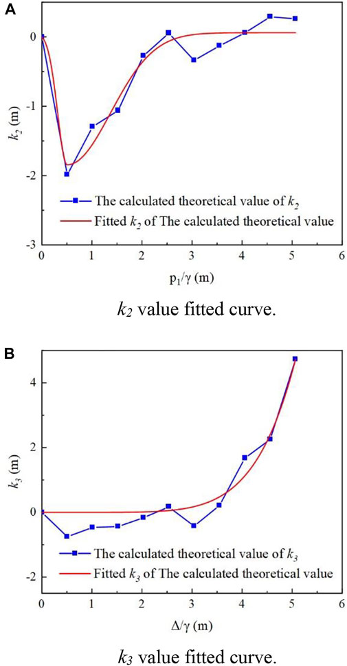
FIGURE 10. The fitting of correction parameters in the asymmetric case. (A) k2 value fitted curve. (B) k3 value fitted curve.
By fitting, it is possible to get the following equation for the influence range of the bigger side spatial effect of the load under asymmetric loads:
Which
5.3.2 Smaller load side equation correction
On the side with a lighter load, the ratio of the load value to the soil weight on this side is the independent variable of the correction factor k1, while the ratio of the load difference between the two sides of the foundation pit and the soil weight is the independent variable of the correction factor k3. Eq. 10 depicts the form of the correction equation. Taking into account the findings of Table 4’s calculations, the value of k3 in Eq. 10 is fitted, as depicted in Figure 10B.
By fitting, it is possible to get the following equation for the influence range of the smaller side spatial effect of the load under asymmetric loads:
Which
5.3.3 Equation validation
Equation. 11 produced by correction on the side with the greater load is plotted to obtain the image depicted by the curve in Figure 11A. For calculation and verification purposes, the load values on the side with the smaller load are 20 kPa and 40 kPa, respectively, while the load values on the side with a larger load are altered. As shown in Figures 11A a total of seven sets of validation data were acquired. The validation data basically match the fitted equation.
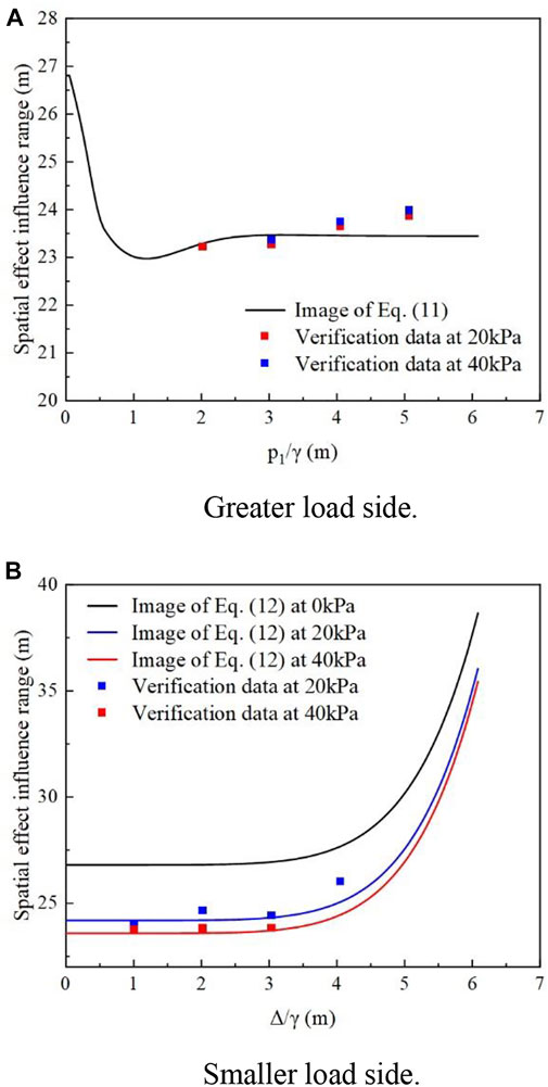
FIGURE 11. Images and validation data of the equation for the influence range of spatial effects under asymmetric loads. (A) Greater load side. (B) smaller load side.
The smaller side of the load is corrected to obtain Eq. 12, and two variables, the load on the smaller side of the load and the absolute value of the load difference between the two sides of the foundation pit, need to be considered. Three curves are plotted according to Eq. 12 for the load on the smaller side as 0 kPa, 20 kPa, and 40 kPa, as shown in Figure 11B. Verification of the data change trend and the magnitude of the value, as well as the results of the equation computation, are essentially the match. This demonstrates the reliability of the fitted equation.
6 Conclusion
This work proposed the equation of the influence range on the spatial effect of the foundation pit considering the load. A series of numerical computation tests were done in order to examine the three-dimensional deformation of the diaphragm wall under various loading conditions. The main conclusions obtained are summarized as follows.
1) This study introduces a “notch-type” soil settlement model as a three-dimensional spatial effect discriminator based on the “plane strain ratio”. The concept of “plane strain ratio assuming maximum surface settlement” is proposed to quantify the development of spatial effects in asymmetric foundation pits.
2) When the load is small (in the case of 0–20 kPa), the spatial effect of the foundation pit is larger. With the increase of the external load value (in the case of 30–100 kPa), the spatial effect of the foundation pit gradually decreases and stabilizes, fluctuating in the range of 23.01–23.84 m. On this basis, the equation of the influence range of the foundation pit spatial effect considering the internal support and the out-of-pit stacking load is modified and fitted.
3) Under the action of the asymmetric load, the load on one side of the foundation pit governs the spatial effects on that side. When the load on both sides of the foundation pit is small (10–30 kPa for the larger side), the spatial effect of the bias side is reduced. When the load difference between the two sides of the foundation pit is significant (80–100 kPa for the larger side), the spatial effect of the smaller side grows rapidly.
4) For verification purposes, the data obtained from the calculation example were modified to fit the equations for the influence range of spatial effect on the side with a larger load and the side with a smaller load and were compared with the validation conditions. Considering the development of spatial effect of foundation pit from the perspective of out-of-pit settlement can serve as a reference point for the interaction between foundation pit and surrounding environment.
The theory presented in this study is only for pure shear 3D failure mode of pit wall soil mass, for tension crack-shear 3D failure mode of pit wail soil mass is still lack of discussion. At the same time, the validation of the proposed formula needs to be further clarified by field monitoring data or experimental studies for its applicability.
Data availability statement
The original contributions presented in the study are included in the article/supplementary material, further inquiries can be directed to the corresponding author.
Author contributions
CX, ZL, and YJ are the main accomplishers of this work and have completed most of the numerical simulation and theoretical work. YS, XF, ZX and YL assisted in the data processing and geotechnical tests.
Funding
This work was supported by National Science Fund for Distinguished Young Scholars (NSFC Grant No. 51725802), National Natural Science Foundation of China (NSFC Grant No. 51878276) and Jiangxi Natural Science Foundation (No.20212BAB204012).
Conflict of interest
The authors declare that the research was conducted in the absence of any commercial or financial relationships that could be construed as a potential conflict of interest.
Publisher’s note
All claims expressed in this article are solely those of the authors and do not necessarily represent those of their affiliated organizations, or those of the publisher, the editors and the reviewers. Any product that may be evaluated in this article, or claim that may be made by its manufacturer, is not guaranteed or endorsed by the publisher.
References
Bai, B., Xu, T., Nie, Q., and Li, P. (2020). Temperature-driven migration of heavy metal Pb2+ along with moisture movement in unsaturated soils. Int. J. Heat Mass Transf. 153119573, 119573. doi:10.1016/j.ijheatmasstransfer.2020.119573
Bai, B., Yang, G., Li, T., and Yang, G. (2019). A thermodynamic constitutive model with temperature effect based on particle rearrangement for geomaterials. Mech. Mater. 139103180, 103180. doi:10.1016/j.mechmat.2019.103180
Bai, B., Zhou, R., Cai, G., Hu, W., and Yang, G. (2021). Coupled thermo-hydro-mechanical mechanism in view of the soil particle rearrangement of granular thermodynamics. Comput. geotechnics 137104272, 104272. doi:10.1016/j.compgeo.2021.104272
Chang, J. X., Yuan, L. X., Hai, H. L., and Feng, M. S. (2013). Influences of vehicle loads on braced excavation in soft clay. Appl. Mech. Mater. 2545, 353–356.
Chang-Yu, O., and Bor-Yuan, S. (1998). Analysis of the corner effect on excavation behaviors. Can. Geotech. J. 35 (3), 532–540. doi:10.1139/t98-013
Chang-Yu, O., Bor-Yuan, S., and I-Wen, W. (2000). Three-dimensional deformation behavior of the Taipei National Enterprise Center (TNEC) excavation case history. Can. Geotech. J. 37 (2), 438–448. doi:10.1139/t00-018
Chang-Yu, O., Dar-Chang, C., and Tzong-Shiann, W. (1996). Three-dimensional finite element analysis of deep excavations. J. Geotech. Engrg. 122 (5), 337–345. doi:10.1061/(asce)0733-9410(1996)122:5(337)
Chen, H., Li, L., Li, J., and Sun, D. (2022). A generic analytical elastic solution for excavation responses of an arbitrarily shaped deep opening under biaxial in situ stresses. Int. J. Geomech. 22 (4). doi:10.1061/(ASCE)GM.1943-5622.0002335
Chen, H., and Mo, P. (2022). An undrained expansion solution of cylindrical cavity in SANICLAY for K0-consolidated clays. J. Rock Mech. Geotechnical Eng. 14 (3), 922–935. doi:10.1016/j.jrmge.2021.10.016
Chen, H., and Zhang, L. (2022). A machine learning-based method for predicting end-bearing capacity of rock-socketed shafts. Rock Mechanics and Rock Engineering. doi:10.1007/S00603-021-02757-9
Chenghua, W., Xiaoxuan, W., Khu, S., Makropoulos, C., and Nield, D. A. (2018). A quantitative analysis of the spatial effects of retaining structure for slender foundation pits. IOP Conf. Ser. Earth Environ. Sci. 189 (2), 022036. doi:10.1088/1755-1315/189/2/022036
Cui, X., Fan, Y., Wang, H., and Huang, S. (2020). Ground environment characteristics during the operation of GWHP considering the particle deposition effect. Energy Build. 206109593, 109593. doi:10.1016/j.enbuild.2019.109593
Fan, X., Phoon, K., Xu, C., and Tang, C. (2021). Closed-form solution for excavation-induced ground settlement profile in clay. Comput. Geotechnics 137104266, 104266. doi:10.1016/j.compgeo.2021.104266
Finno, R. J., Blackburn, J. T., and Roboski, J. F. (2007). Three-dimensional effects for supported excavations in clay. J. Geotech. Geoenviron. Eng. 133133 (1), 301–336. doi:10.1061/(asce)1090-0241(2007)133:1(30)
Guo, P., Gong, X., and Wang, Y. (2019). Displacement and force analyses of braced structure of deep excavation considering unsymmetrical surcharge effect. Comput. Geotechnics 113103102, 103102. doi:10.1016/j.compgeo.2019.103102
Li, D., Tang, D., and Yan, F. M. (2014). Mechanics of deep excavation's spatial effect and soil pressure calculation method considering its influence. J. Zhejiang Univ. Eng. Sci. 48 (09), 1632–1639+1720.
Li, L., Chen, H., Li, J., and Sun, D. (2021). An elastoplastic solution to undrained expansion of a cylindrical cavity in SANICLAY under plane stress condition. Comput. Geotechnics 132, 103990. doi:10.1016/j.compgeo.2020.103990
Li, L. J., and Liang, R. W. (2011). Research on the spatial effect of double row piles structure system in deep foundation. Adv. Mat. Res. 374, 2367. doi:10.4028/www.scientific.net/amr.374-377.2367
Lin, G., Xu, C., and Cai, Y. (2010). Research on characters of retaining structures for deep foundation pit excavation under unbalanced heaped load. Rock Soil Mech. 31 (08), 2592–2598.
Liu, B., Zhang, D., and XI, P. (2019). Influence of vehicle load mode on the response of an asymmetrically-loaded deep excavation. KSCE J. Civ. Eng. 23 (8), 3315–3329. doi:10.1007/s12205-019-0511-6
Luo, Z., Hu, B., Wang, Y., and DI, H. (2018). Effect of spatial variability of soft clays on geotechnical design of braced excavations: A case study of formosa excavation. Comput. Geotechnics 103, 103242–103253. doi:10.1016/j.compgeo.2018.07.020
Mangushev, R. A., Osokin, A. I., and Garnyk, L. V. (2016). Experience in preserving adjacent buildings during excavation of large foundation pits under conditions of dense development. Soil Mech. Found. Eng. 53 (5), 291–297. doi:10.1007/s11204-016-9401-9
Mingfeng, L. P. C. S., Peng, L. M., Shi, C. H., Zhang, Y. L., and Li, W. H. (2011). A simplified calculation method for spatial effect in large-long-deep foundation pit and its analysis. Adv. Mat. Res. 243-249, 2762–2770. doi:10.4028/www.scientific.net/amr.243-249.2762
Ou, X., Zhang, X., Fu, J., Zhang, C., Zhou, X., and Feng, H. (2020). Cause investigation of large deformation of a deep excavation support system subjected to unsymmetrical surface loading. Eng. Fail. Anal. 107104202, 104202. doi:10.1016/j.engfailanal.2019.104202
Pio-Go, H., and Chang-Yu, O. (1998). Shape of ground surface settlement profiles caused by excavation. Can. Geotech. J. 35 (6), 1004–1017. doi:10.1139/t98-056
Roboski, J., and Finno, R. J. (2006). Distributions of ground movements parallel to deep excavations in clay. Can. Geotech. J. 43 (1), 43–58. doi:10.1139/T05-091
Shouhua, L., Junsheng, Y., Jinyang, F., and Xiangcou, Z. (2019). Performance of a deep excavation irregular supporting structure subjected to asymmetric loading. Int. J. Geomech. 19 (7). doi:10.1061/(asce)gm.1943-5622.0001468
Sun, H., Chen, Y., Zhang, J., and Kuang, T. (2019). Analytical investigation of tunnel deformation caused by circular foundation pit excavation. Comput. Geotechnics 106, 106193–106198. doi:10.1016/j.compgeo.2018.11.001
Tanner Blackburn, J., and Finno, R. J. (2007). Three-dimensional responses observed in an internally braced excavation in soft clay. J. Geotech. Geoenviron. Eng. 133133 (11), 136411–141373. doi:10.1061/(asce)1090-0241(2007)133:11(1364)
Wang, K., Li, W., Sun, H., Pan, X., Diao, H., and Hu, B. (2021). Lateral deformation characteristics and control methods of foundation pits subjected to asymmetric loads. Symmetry 13 (3), 476. doi:10.3390/sym13030476
Xu, C., Chen, Q., Wang, Y., Hu, W., and Fang, T. (2016). Dynamic deformation control of retaining structures of a deep excavation. J. Perform. Constr. Facil. 30 (4). doi:10.1061/(asce)cf.1943-5509.0000819
Xu, C. J., Yin, M., and Lin, G. (2013). Characters analysis of the retaining structure of the foundation pit under local load. Appl. Mech. Mater. 477-478, 448–452. doi:10.4028/www.scientific.net/amm.477-478.448
Xu, C., Xu, Y., Sun, H., Chen, Q., and Zhang, X. (2013). Characteristics of braced excavation under asymmetrical loads. Mathematical problems in engineering, 20131–12. doi:10.1155/2013/452534
Yang, X., Liu, Z., and He, S. (1998). Research about spatial effect of deep pit supporting. Chin. J. Geotechnical Eng. 02, 74–78., No.
Yao, A., and Zhang, X. (2011). Influence of asymmetric load on supporting deformation for deep foundation pit. Rock Soil Mech. 32 (S2), 378–382+388.
Zeng, F., Zhang, Z., Wang, J., and Li, M. (2018). Observed performance of two adjacent and concurrently excavated deep foundation pits in soft clay. J. Perform. Constr. Facil. 32 (4), 04018040. doi:10.1061/(ASCE)CF.1943-5509.0001184
Zhang, J., Xie, R., and Zhang, H. (2018). Mechanical response analysis of the buried pipeline due to adjacent foundation pit excavation. Tunn. Undergr. Space Technol. 78, 78135–78145. doi:10.1016/j.tust.2018.04.026
Keywords: asymmetrical foundation pit, ground settlement, spatial effects, 3D FEM, range of influence
Citation: Xu C, Lin Z, Jiang Y, Shi Y, Fan X, Xiong Z and Liu Y (2022) Research on the spatial effect of foundation pit under asymmetric loads. Front. Mater. 9:976696. doi: 10.3389/fmats.2022.976696
Received: 23 June 2022; Accepted: 28 July 2022;
Published: 01 September 2022.
Edited by:
Xianze Cui, China Three Gorges University, ChinaReviewed by:
Lin LI, Chang’an University, ChinaWenbing Wu, China University of Geosciences Wuhan, China
Copyright © 2022 Xu, Lin, Jiang, Shi, Fan, Xiong and Liu. This is an open-access article distributed under the terms of the Creative Commons Attribution License (CC BY). The use, distribution or reproduction in other forums is permitted, provided the original author(s) and the copyright owner(s) are credited and that the original publication in this journal is cited, in accordance with accepted academic practice. No use, distribution or reproduction is permitted which does not comply with these terms.
*Correspondence: Yalong Jiang, eWFsb25namlhbmdAd2h1LmVkdS5jbg==