 Vincent K. Maes
 Arjun Radhakrishnan
 Diego Lombetti2
 James Kratz
- 1Bristol Composites Institute, University of Bristol, Bristol, United Kingdom
- 2Composite Technology Facility, Rolls-Royce Plc, Bristol, United Kingdom
Curing of composite material parts often rely on slow cure cycles to manage exotherms and avoid hot or cold spots in the part. This is especially true for larger, thicker and/or geometrically complex parts, which suffer from unevenness in heating between different regions of the part stemming from thickness variations and made worse by the use of convection heating in ovens and autoclaves. An alternative technology for moulding is using heated tooling, which improves the energy efficiency of the process but can also significantly increase the tooling costs. However, the true power of heated tooling is in the ability to tailor the temperature profile in different regions. By introducing zonal heating, significantly faster process cycles can be achieved, hence improving production rates. Using cure simulation, two identical components are analysed, one part produced using convection heating (i.e., oven) and the second made using direct heating (i.e., heated tooling). The zonal approach was tuned based on numerical models and shows a reduction of 17.5% in terms of cure time and the experimental trials found an approximate 45% reduction in energy consumption.
1 Introduction
Moulding composite materials is an energy-intensive activity, generally relying on ovens and autoclaves, and is required to produce the final shape of the component and achieve the desired material properties. To meet quality requirements, slower heat rates and longer dwells are often used, especially for larger, thicker and/or geometrically complex parts in an attempt to maintain homogenous temperature profiles throughout the part as it cures (i.e., avoid hot or cold spots which result in undesirable cure gradients). This is because ovens and autoclaves, which transfer heat through convection, can leave large and/or complex parts with significant thermal gradients, which in turn lead to residual stresses and potential distortions or even damage in the final cured part if not mitigated. Even with slower heating rates and intermediate dwells introduced to cure cycles, thick and complex parts can often experience huge variations in the rate of cure resulting in some regions transitioning from liquid to glassy before other regions. The cure gradients lead to residual stresses which increase part warpage and can lead to microcracking or delamination (Bogetti and Gillespie, 1991). To resolve this, various studies have looked into using optimization of the cure cycles (i.e., fine-tuning of ramp rates and dwell times and temperatures) to manage the exotherm resulting in more even temperatures and hence cure development throughout the part, though generally at the cost of increased cure times (Struzziero and Skordos, 2017).
Alternatively, a different approach to introducing heat could be used, such as direct conduction in the form of heated tooling (Marsh, 2003; Progoulakis, 2004; Rzgar, 2015). With heated tooling, heat is introduced directly to the tool surfaces or volume through heated fluid circulation (Abdalrahman et al., 2016) or heating elements (Athanasopoulos et al., 2013). While this improves the energy efficiency of the process, it also significantly increases the tooling costs and is hence generally not adopted in the industry for large parts. However, the true power of heated tooling is not in reducing the energy consumed for a standard cure cycle (i.e., as a direct replacement to an oven or autoclave process), but rather in the ability to tailor the temperature profile applied to different regions (Weiland et al., 2017). By introducing zonal heating, significantly faster process cycles can be achieved while reliably meeting the optimal part quality by reaching moulding temperatures quicker and more uniformly (Smith et al., 2013) even for complex parts with thick tooling. A faster cure cycle using heated tooling then brings savings both in reducing the energy bill as well as in allowing greater throughput, hence allowing more parts to be produced using a smaller factory footprint.
This work seeks to demonstrate the ability of zonally heated tooling to produce large thickness variation parts to the same or better quality standards as compared to traditional single zone (i.e., oven and autoclave) curing with faster cure cycles. Quality within the context of this work is measured by the variation in degree of cure within the part through-out the cure cycle, where a more homogeneous development of degree of cure is considered to be indicative of good quality whereas large differences in degree of cure between different regions of the part are considered to imply poor quality. To carry out the work, cure simulations are used to investigate two identical components. One part relied on the oven for heat with a traditional convection heating cycle and the second used electric cartridges with different temperature profiles to achieve an accelerated and zonally defined heating cycle. Experimental parts were then produced to confirm the simulation results and allow for energy measurements to be made. These measurements, taken during both cure set-ups, allows assessment of the gains in terms of energy efficiency when shifting from indirect convection heating in an oven to direct heating with heater mats.
2 Methodology
2.1 Part and tooling material and geometry
The part design was chosen to contain both thick and thin regions, as well some overall geometric complexity that would influence the air flow around it when heated using an oven. The cross-section of the design is shown in Figure 1. The physical part is a 150 mm deep extrusion of this shape. The tooling shown is made from 3 parts of 8 mm thick 304 stainless steel which were bent to shape and finished using CNC machining for exact part dimensions and smooth lay-up surface. Post machining the tool thickness was reduced slightly for the lower part around the corner where thickness was 6 mm. The pieces are brought together to form a two-sided tool and cork is used as shown in to fill gaps on either side of the part. These gaps are introduced to allow a nearly closed mould at the start of cure while also accommodating compaction during cure.
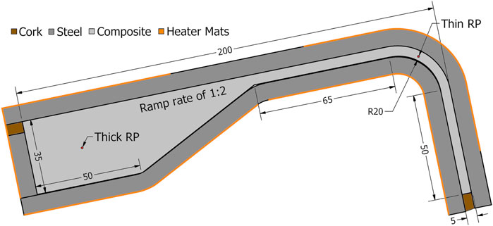
FIGURE 1. 2D cross-sectional view of design, incl. tooling and qualitative indication of heater mat positions, with key part dimensions in millimetres.
The composite material chosen in this work is SHD MTC400, an epoxy resin, which is reinforced with a twill fabric made of T700 carbon fibre of 415 gsm aerial weight and with 38% resin weight content. This material was chosen as an aerospace representative grade system, i.e., it has a glass transition temperature around 200°C, and in part due to its reactivity which makes it challenging to cure thicker parts without incurring significant exotherms that cause an internal overshoot of temperature above the target cure temperature. In extreme cases the heat from the exotherm can result in deterioration of the matrix, but even with minor overshoots can result in elevated internal stresses. For the analysis and prediction of the thermal behaviour during the cure cycle, the key material parameters include the density,
TABLE 1. Thermal properties of composites material, steel, and cork.
The final component required to define the material system is the cure kinetics, defined by the DoC rate function, see Eq. 4, and the total heat of reaction, H, which is taken as 543 J/g (Gaska, 2021). The coefficients of the cure kinetics are given in Table 2.
TABLE 2. Cure kinetic parameters for MTC 400 resin system (Gaska, 2021).
2.2 Numerical model and cure cycle selection
The numerical model used to run the cure simulations was set up using the heat transfer analysis in ABAQUS, a simplified 2D cross-sectional approach was used relying on the width of the part being sufficient to allow the part to be approximated by its midplane. Meshing was done using a mixture of quadrilateral and triangular elements and a target element edge length of 1 mm, to ensure sufficient elements in the thinner region to capture any through thickness gradients, see Figure 2. The analysis was transient with an initial homogeneous temperature 20°C and initial time stepping of 30 s and a constraint on the maximum change in temperature in any material point of 2°C for any single time step. This was needed to ensure any exotherms were sufficiently time resolved. The ABAQUS solver was allowed to adjust the time steps down to meet the target maximum temperature change but was prevented from taking time steps greater than 30 s.
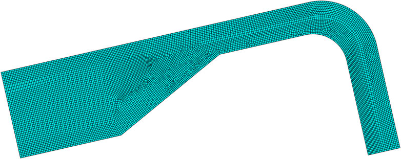
FIGURE 2. Mesh used for cure simulation in ABAQUS.
For the oven cure simulation, the entire outer edge of the tooling and cork was simulated as having convection heating using the surface film interaction condition. The heat transfer coefficient was set to 10 W/(m2·K) and the sink temperature was set to be the air temperature profile as programmed into the oven controller and confirmed via thermocouple. For the heated tooling assisted cure, the same boundary edges were divided into three regions, two of which correspond to regions with different target temperature profiles and the third correspond to gaps between the heater mats where a convection boundary condition was applied using the same heat transfer coefficient of 10 W/(m2·K) but now using a sink temperature of 20°C, simulating room temperature heat leakage. The first of the heater mat regions contained the boundaries of the thick and ramped regions and the second heater mat region contained the boundaries of the thin and corner regions. Figure 3 shows the part prior to bagging, showing the placement of the heaters and the gaps.
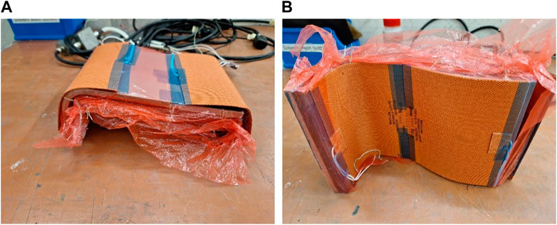
FIGURE 3. Part, pre-bagging, with heater mats on top surface (A) and bottom surface (B), showing placement and gaps.
For each of these set-ups, a two-stage cure cycle was manually tuned to limit the exotherm occurring in the thick region to be around the target final cure temperature of 120°C. For the heated tooling model, the zonal heating was further used to target a more even heat up rate and DoC development throughout the composite material volume. To check these metrics, two reference points (RP) were used to extract the local temperature and DoC throughout the cycle in the centre of the thick region, Thick RP, and in the centre of the corner, Thin RP, as indicated in Figure 1.
2.3 Manufacturing and experimental set-up
The lay-up surface was treated with 5 coats of release agent before each part was manufactured. In addition, release film was used between the lay-up surface and the first ply. The pre-preg material, with a nominal cured ply thickness of 0.43 mm, was cut to size by hand. For the thick region a total of 82 plies were used and for the thin region a total of 12 plies were used, resulting in a theoretical cured thickness of 35.26 and 5.16 mm in these regions, respectively. During lay-up, cold de-bulks were used at regular intervals to reduce thickness build up. In the middle of the stack, thermocouples were introduced at the approximate location matching the RPs, as identified in Figure 1, to allow comparison of thermal profiles between the simulation and the experiments. The thermal profile was combined with the cure kinetics model to predict the cure development in these regions for the manufactured parts.
Thermocouples were also added on the outer surface of the tooling to track the boundary condition. In the case of the zonal heating experiment, an additional set of thermocouples were needed on the outside surface of the tool as input to the controller units. The entire tool part assembly, including heater mats for the zonally heated experiment, was then bagged and a final thermocouple was added externally to the bag to track ambient air temperature. Bag integrity was checked with no drop in vacuum observed within 10 min of disconnecting the vacuum hose. Both oven and heater mat experiments took place in a Carbolite oven, in the case of the heater mat experiment the oven served as a heat proof chamber and was turned off. Vacuum was maintained using an external vacuum pump that remained on at maximum vacuum, indicated on the pump’s gauge at 30 mHg, throughout the cure cycle. For the oven cured part, the oven temperature set point was controlled using the in-built controller, while for the zonally heated cured part the four heater mats were each managed by a separate external Watlow PID controller which was fed by a single power unit.
For both curing cycles, an Energy Logger (TinyLogger) was used to monitor the average current drawn by either the oven or the central power unit used to power all the heater mats, at an interval of 30 s. The TinyLogger was also plugged into the lab main circuit to allow monitoring of the voltage and hence allow computation of the power used. As the TinyLogger used can only measure a single power output it was not possible to measure the heater mats individually. An affordable system for parallel power measurements is being developed to allow future studies to capture readings of individual heater mats. The thermocouples were monitored using a datalogger (PicoLogger) at the same interval of 30 s. However, as the ovens/heater mat controllers, PicoLogger Laptop, and TinyLogger were not connected the data sets are not time synchronised as they are manually started one at a time. However, the data is synchronised post-manufacturing using timestamps as the different devices were within 10 s of one another which is considered acceptable given the multi-hour nature of the cure cycle.
3 Results
3.1 Cure cycle design
The baseline cure cycle for this material for standard thickness laminates is a single hold cure at a temperature anywhere between 80°C and 135°C, with a hold time of 16 h for the low temperature cure and only 1 h at the higher temperature. Due to the reactivity of the material and the thickness of the chosen part, however, the higher hold temperature is not viable due to the exothermic peak of up to 235°C that would be generated, according to the model, in such a scenario. For this reason, an intermediate dwell at 90°C was introduced. At this temperature the material begins to react, and the thick region experiences a mild exotherm that brings this region up to around 120°C, the targeted final cure temperature. The second ramp then brings the rest of the part to this temperature for the final hold and cure.
The final cure cycles are given in Figure 4, where the initial ramp rate and hold temperature are identical for both the single zone and the dual zone cure cycles. Ramp rates were kept to 2°C/min to ensure even heating in both scenarios. While both the oven and heater mats are capable of heating faster, this can cause thermal gradients within the oven or across the heater mats that are undesirable when attempting to create a more homogeneous temperature profile within the part. For the single zone (i.e., oven) scenario, the second ramp is delayed allowing thick region exotherm to pass before additional heat is added to the system which would otherwise worsen the peak temperature caused by the exotherm. On the other hand, the dual zone (i.e., heater mat) scenario allows the second ramp to initiate earlier in the thin region only. This separation of the regions also allows the overall cure cycle to be reduced by 17.5% while ensuring uniform final DoC throughout the part. In the single zone cure, due to the delay in ramping up to the final temperature, the thin region lags in cure development requiring the overall cure cycle to be extended in order to allow it to catch up and achieve a part with roughly even cure throughout at the end of the final dwell.
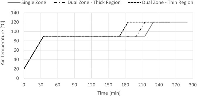
FIGURE 4. Air temperature profiles for single and dual zones.
3.2 Exotherm and degree of cure
Using the selected cure cycles, single zone and dual zone simulations were carried out and parts were made using an oven and heater mats for experimental validation. The thermal profiles at the selected RPs for the single zone oven cure are as shown in Figure 5 for both simulation and experiment. The figure also shows the oven air temperature and tool temperature above the thick RP as well as power measurements. The experimental thermal profiles for the tool for the thin region and simulation results are not included as no discernible differences were found between them and the corresponding RP thermal profiles.
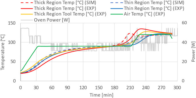
FIGURE 5. Temperature as simulated and experimentally measured at mid-thickness in thick and thin region for single zone cure, accompanied by the power usage of the oven as measured.
These temperature profiles show the significant difference in temperature between the thick and thin regions, which is present both in the simulations and the experimental measurements. In the simulation the maximum difference is around 20°C, while for the experiments it was around 34°C. The experimental data shows an additional delay in the temperature and consequently an elevated exotherm. From previous experience it is known that the effective heat transfer in the oven is variable and hence it is expected the difference stems from the heat transfer being lower during the experimental trial than simulated. Thermal lag between the air, tool, and thick region is also highlighted by the experimental temperature profiles. From the power data it can be seen that there is a spike in energy usage both during the initial and secondary ramps.
For the dual zone heater mat approach, as shown in Figure 6, the differences between the thick and thin regions in both simulation and experimental profiles are smaller. For the simulation, the thick and thin region have a closely matching temperature profile. In the experiment, the thin region was found to follow the simulated response closely, but the thick region experienced an exotherm of roughly 20°C which was not predicted by the simulation. The thick region also shows a thermal lag not found in the simulation. The tool temperature thermocouples, which are directly under the heater mat, show no lag and hence confirm the heater mats are following the target cure cycles well. For thin section, the tool temperature shows a decent match to the RP. Finally, the air temperature shows a rise from 20°C to around 40°C, exemplifying the passive heat loss within this set-up. It is evident from the power data that the heater mats require less energy to achieve the required cure cycle.
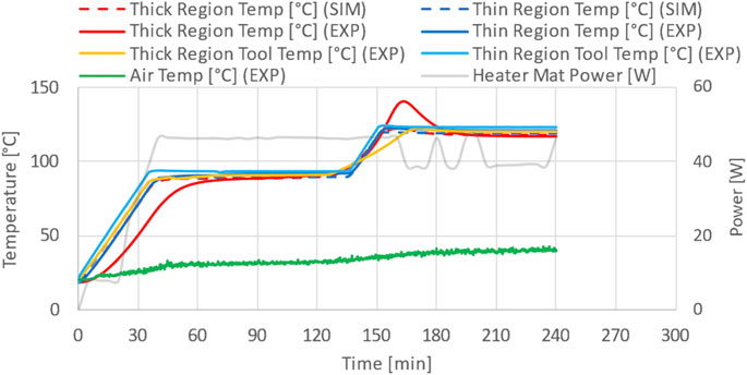
FIGURE 6. Temperature as simulated and experimentally measured at mid-thickness in thick and thin region for dual zone cure, accompanied by the power usage of the heater mats as measured.
The differences in the thermal profiles result in a difference in the cure development. For the single cure zone, the degree of cure development, calculated by feeding the simulated and measured temperature profiles to the cure kinetics model is shown in Figure 7. For the simulation, the maximum difference in DoC between the thick and thin region, occurring just after the exothermic peak, is around 0.3, with the thick region surpassing a DoC of 0.9 while the thin region is still below 0.6 (gel point). Such a large DoC variation implies that the polymer in the thick region will begin to gel and carry load while the thin region is still in liquid form. Combined with the thermal gradient this can result in internal thermal stresses and potential distortions and/or micro-cracking. For the experimental data, the degree of cure profiles are still similar, appearing mostly to be shifted in time. The overall comparison between the thick and thin region still shows a large difference in degree of cure development, with a maximum delta of 0.43.
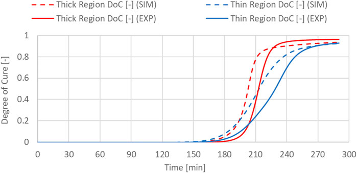
FIGURE 7. Degree of Cure calculated using simulated and measured temperature data at mid-thickness in thick and thin region for single zone cure.
For the dual zone heater mat approach, the degree of cure development as computed using the temperature profiles are shown in Figure 8. From these it can be observed that the difference in degree of cure development between thick and thin region are reduced for both the simulation and experimental data. This validates the ability of zonal heating to avoid some of the complications cause by using the oven as the separate thermal control for the thin and thick regions can create a better match in DoC development in both regions. In the dual zone approach, the maximum difference in DoC is reduced to below 0.05 which occurs well before gelation with the DoC being effectively identical from 0.2 onwards for the simulated data. For the experimental data the match is not as close but is still improved significantly compared to the oven cure, with the maximum difference in DoC being reduced to 0.18 and showing a very close match beyond the gel point.
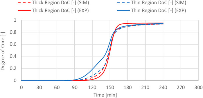
FIGURE 8. Degree of Cure calculated using simulated and measured temperature data at mid-thickness in thick and thin region for dual zone cure.
Overall, it can be observed that the dual zone heating approach allows very close match in thermal history and DoC development even though the thickness ratio is 1:7 with the thick region exotherming which the thin region does not do. This close match in DoC development is taken to be indicative of superior quality as DoC gradients have been linked to residual stresses (Bogetti and Gillespie, 1991). Even though the match is not as close as predicted by the simulation, the experiments still show the dual zone approach to achieve better cure development homogeneity.
3.3 Energy usage
Integrating the power measurements taken during the two cure approaches by the TinyLogger, it is possible to compare the overall energy usage of single zone oven curing and dual zone heater mat curing. For the single zone part the total energy consumption was 0.278 kWh, while for the dual zone curing to total energy consumption was measured as only 0.154 kWh. This represents an energy saving of around 45%. This value is affected by both the size and efficiency of the oven as well as the exothermic nature of the part. It is also worth noting that for the zonal heated part, where the oven was off, the ambient air temperature inside the oven was observed to increase to around 40°C from 20°C.
4 Discussion
The key observations from the numerical and experimental trials relate to the improved efficiency, both in terms of time and energy consumed, and the improved part quality, in terms of closer match in DoC development throughout the part. In reality, these changes are the compound effect of both the switch to direct heating and multi-zonal heating. A more nuanced analysis, which separates these two effects would require an additional part to be made using the heater mats with a single zone thermal profile. As this part is missing, the energy savings cannot be accurately split between the two factors. However, the changes in part quality through improved homogeneity of the cure development can be attributed solely to the use of dual zone heating.
The gains observed for the multi-zone, direct heated part were initially predicted from the simulations and then largely confirmed in the experiments. However, the experiments did show a noticeable exotherm not predicted by the simulations. This can be attributed to several approximations involved in the model. The first approximations are the thermal properties of the composite materials, which were not characterised in this study but based on previous studies on similar systems. Characterisation of the conductivity properties of this specific system could refine these properties and hence improve predictions. The second set of approximations, is expected to contribute significantly to the thermal lag and subsequent exothermic peak, is the heat loss to the ambient air. This approximation is fed by two aspects; the 2D nature of the simulation and the heat transfer coefficient. The oven heat transfer coefficient is naturally low due to the slow air circulation speed and ambient pressure. It is furthermore dependent on the ambient air conditions as the oven used is not a perfectly sealed system (i.e., access ports through which the wires of the thermo-couples and heater mats are passed). This makes it difficult to accurately characterise the heat transfer between the oven air and the part, especially in the case of the dual zone heater mat cured part as for this the oven is turned off and hence there is even less air circulation. The difference in actual heat transfer during the cure cycle and the approximated heat transfer coefficient used in the simulation can easily differ enough to obtain the observed increase in the exotherm of 15.1°C overshoot for single zone oven curing and 20.4°C overshoot for the dual zone heater mat based curing as the temperature overshoot is very sensitive to the efficiency with which the heat generated can be shed to the air. Improved prediction could be possible using a 3D model as it can capture heat transfer across the sides of the part, which would be a source of heat gain in the oven model and heat loss in the heater mat model. There will, likely, always be a limit to the accuracy of the simulations. Therefore improved robustness of the cure cycle and management of the exotherm could be achieved by using machine learning techniques such as those developed by Humfeld et al. (2021) to adaptively control the set points of the heater mats based on the thermocouple data and the numerical model.
Alternatively, the behaviour of the dual zone approach could be improved by using a closed system using a liquid heat exchanger. This would allow an equally efficient heat addition and extraction rather than efficient heat addition from the heater mats and inefficient heat extraction from convection to the ambient oven air. Use of a liquid heat exchanger would then also allow better insulation of the part, which would likely result in further energy savings. However, such a system is more complex, expensive, and space consuming, than using heater mats.
5 Conclusion
In this study a thick and complex part was simulated to evaluate the ability of zonally controlled heated tooling to better manage the exotherm and allow for a more even thermal and cure development profile. Numerical simulations were used to design both the single and dual zone cure cycles. The predictions were experimentally checked using trial parts with embedded thermocouples. The experimental results showed an exotherm not predicted by the simulation. This difference is expected to stem from approximations used for the thermal properties of the composite material, the low and variable heat transfer in the oven, which is difficult to characterise and simulate, and the use of a 2D model instead of a full 3D simulation.
However, the experimental trials confirmed the improvements in matching DoC development as was predicted by the simulations. Large spatial gradients in vicinity of the gelation are known to result in larger residual stresses that are detrimental to part quality and performance. The dual zone approach reduced such spatial gradients in temperature and DoC. This reduction can be attributed to the independent thermal control (tuning) of the thick and thin zones, leading to similar thermal history and cure development, without worsening the exotherm from added heat.
Furthermore, compared to single zone oven, dual zone heater mat approach was able to reduce the cycle time by 17.5% with experimental measurements showing a reduction of 45% in energy consumption. The reduced energy consumption is achieved through the combination of reduced cycle time and the shift to more efficient direct heating of the tool surface.
In future work, more advanced direct heating systems are of interest for improved control. This will then allow cure cycles that use heating, active cooling, and reheating (Kim and Lee, 1997). Combined with the zonal approach demonstrated here, this is expected to further improve the management of the exotherm and reduce the cure cycle time while matching thermal history and DoC development throughout the part.
Data availability statement
The raw data supporting the conclusion of this article will be made available by the authors, without undue reservation.
Author contributions
VM: conceptualization, data curation, formal analysis, funding acquisition, investigation, methodology, project administration, visualization, writing—original draft, writing—review and editing. AR: conceptualization, funding acquisition, investigation, methodology, writing—review and editing. DL: conceptualisation, funding acquisition, supervision, writing—review and editing. JK: conceptualisation, funding acquisition, methodology, project administration, supervision, writing—review and editing.
Funding
This work was supported through the Bristol Impact Acceleration Account under the EPSRC grant EP/R511663/1 as well as by the Future Composites Manufacturing Research Hub under the EPSRC grant EP/P006701/1. The support is gratefully acknowledged.
Acknowledgments
This work was carried out at the Bristol Composite Institute under the supervision and with the assistance of the technical staff. Their input is gratefully acknowledged.
Conflict of interest
Author DL was employed by the company Rolls-Royce Plc.
The remaining authors declare that the research was conducted in the absence of any commercial or financial relationships that could be construed as a potential conflict of interest.
Publisher’s note
All claims expressed in this article are solely those of the authors and do not necessarily represent those of their affiliated organizations, or those of the publisher, the editors and the reviewers. Any product that may be evaluated in this article, or claim that may be made by its manufacturer, is not guaranteed or endorsed by the publisher.
References
Abdalrahman, R., Grove, S., Kyte, A., and Rizvi, M. J. (2016). Numerical simulation and experimental verification of heating performance of an integrally water-heated tool. J. Reinf. Plastics Compos. 35 (8), 671–687. doi:10.1177/0731684415626804
Ashby, M., Shercliff, H., and Cebon, D. (2018). “Appendix A: Data for engineering materials,” in Materials: Engineering, science, processing and design. 4th ed. (Butterworth-Heinemann).
Athanasopoulos, N., Koutsoukis, G., Vlachos, D., and Kostopoulos, V. (2013). Temperature uniformity analysis and development of open lightweight composite molds using carbon fibers as heating elements. Compos. Part B Eng. 50, 279–289. doi:10.1016/j.compositesb.2013.02.038
Bogetti, T. A., and Gillespie, J. W. (1991). Two-dimensional cure simulation of thick thermosetting composites. J. Compos. Mater. 25 (3), 239–273. doi:10.1177/002199839102500302
Humfeld, K. D., Gu, D., Butler, G. A., Nelson, K., and Zobeiry, N. (2021). A machine learning framework for real-time inverse modeling and multi-objective process optimization of composites for active manufacturing control. Compos. Part B Eng. 223, 109150. doi:10.1016/j.compositesb.2021.109150
Kim, J. S., and Lee, D. G. (1997). Development of an autoclave cure cycle with cooling and reheating steps for thick thermoset composite laminates. J. Compos. Mater. 31 (22), 2264–2282. doi:10.1177/002199839703102203
Lewis, J. R. (1977). “Chapter 19: Physical properties of stainless steels,” in Handbook of stainless steels. Editors D. Peckner, and I. M. Bernstein (New York: McGraw-Hill).
Progoulakis, I. (2004). Heated tooling for aerospace composites manufacture. University of Plymouth.
Rzgar, A. (2015). Integrally- heated tooling for polymer composites. University of Plymouth Research Theses.
Smith, A. W., Goyette, K., Kazanas, C., and Hubert, P. (2013). Development of a heated tooling solution to improve process flexibility for out-of-autoclave prepregs in Proceeding of the International SAMPE Technical Conference.
Struzziero, G., and Skordos, A. A. (2017). Multi-objective optimisation of the cure of thick components. Compos. Part A Appl. Sci. Manuf. 93, 126–136. doi:10.1016/j.compositesa.2016.11.014
Keywords: moulding, zonally heated tooling, tapered composites, energy efficiency, cure simulation
Citation: Maes VK, Radhakrishnan A, Lombetti D and Kratz J (2023) Zonally heated tooling for moulding complex and highly tapered composite parts. Front. Mater. 10:1126932. doi: 10.3389/fmats.2023.1126932
Received: 18 December 2022; Accepted: 24 February 2023;
Published: 09 March 2023.
Edited by:
Lode Daelemans, Ghent University, BelgiumReviewed by:
Marco Gigliotti, École Nationale Supérieure de Mécanique et d'Aérotechnique, FranceQuentin Govignon, IMT Mines Albi-Carmaux, France
Copyright © 2023 Maes, Radhakrishnan, Lombetti and Kratz. This is an open-access article distributed under the terms of the Creative Commons Attribution License (CC BY). The use, distribution or reproduction in other forums is permitted, provided the original author(s) and the copyright owner(s) are credited and that the original publication in this journal is cited, in accordance with accepted academic practice. No use, distribution or reproduction is permitted which does not comply with these terms.
*Correspondence: Vincent K. Maes, dmluY2VudC5tYWVzQGJyaXN0b2wuYWMudWs=