 Yutao Wu
 Yongxin Wang
 Yue Li1,3
- 1Laboratory of Marine New Materials and Related Technology, Zhejiang Key Laboratory of Marine Materials and Protection Technology, Ningbo Institute of Material Technology and Engineering, Chinese Academy of Sciences, Ningbo, China
- 2University of Chinese Academy of Sciences, Beijing, China
- 3School of Materials Science and Engineering, Jiangsu Collaborative Innovation Center for Photovoltic Science and Engineering, Jiangsu Province Cultivation Base for State Key Laboratory of Photovoltaic Science and Technology, Changzhou, China
Polyimide (PI) is widely utilized in the modern industry because of its excellent heat resistance, dielectric properties, radiation resistance and chemical stability. However, PI will appear wear failure due to different working environments in the application of various friction components. In order to ensure the normal function of Pi-based parts and reduce the wear of PI materials, it is necessary to deposit amorphous carbon film with high adhesion strength and wear resistance on PI substrate. In this experiment, we treated polyimide surfaces with carbon plasma to prepare the amorphous carbon films with in situ transition layers. The microstructure, mechanical properties and tribological properties of the amorphous carbon films were studied. The results showed that the hardness and wear resistance of the PI surface were greatly improved by the amorphous carbon film with in situ transition layer. More importantly, the in situ transition endowed the film high adhesion strength on the PI substrate. The roles of the carbon plasma in the deposition process of the amorphous carbon, namely, the deposition effect, and the induction effect, referring to the effect on the top layer of PI substrate, were systematically analyzed. This work realizes the purpose of protecting the PI surface with the amorphous carbon film with high adhesion strength, and also provides a new idea for improving the adhesion between hard coating and flexible substrate.
1 Introduction
Polyimide (PI) is widely utilized in many fields such as aerospace and microelectronics due to its excellent heat resistance, dielectric properties, radiation resistance and chemical stability (Zhang et al., 2006; Zhang et al., 2012). However, when the PI was rubbed against hard objects, its surface is easy to scratch or wear due to its low hardness and low wear resistance (Abbas et al., 2005). Considering that the friction and wear of the material mainly occur on its surface or subsurface, it is necessary to modify surface of the PI. Recently, researchers have found that the deposition of the amorphous carbon films may be an effective way for the protection of flexible substrates (Nakahigashi et al., 2004; Love et al., 2013). The amorphous carbon films are often used as protective coatings for metals, ceramics and polymers due to their excellent properties, such as high hardness, chemical inertness, low friction coefficient and good biocompatibility (Ding et al., 2002; Cuong et al., 2003; Khatir et al., 2014). However, the difference in physical properties such as hardness, thermal expansion coefficient, and toughness between the hard coating and the flexible substrate is likely to result in poor adhesion. The film is easy to crack or peel off under large stress loads, and it is easy to produce an “eggshell effect” (Michler et al., 1998).
Two methods were mainly used to solve this problem. One was to build the gradient layer between the substrate and working surface of the film, the other was to fabricate the composite microstructure of film with low internal stress (Voevodin et al., 1997; Wang et al., 2007; Cai et al., 2013). Since the composite microstructure still could not solve the mismatch between the polymer substrate and amorphous carbon film, the gradient layer was more useful and helpful. It had been demonstrated that the pre-treatment with plasma, which mainly bombards the polymer with high-energy plasma to remove pollutants, would change the physical and chemical properties of the surface (Guo and Chau-Nan Hong, 2003; Raffaele-Addamo et al., 2003). This method provided the way to build the gradient layer from the inner of the top polymer layer, suggesting a good approach to achieve amorphous carbon film on polymer substrate. Cuong et al. used RF plasma enhanced chemical vapor deposition to deposit diamond-like carbon films on polycarbonate surfaces. Polycarbonate was pretreated with argon plasma to remove pollutants. Under the bombardment of argon plasma, the collision between the excited particles and the surface molecules causes the C–C or C–H bond to break, generating free radicals, which then combine with the amorphous carbon film (Cuong et al., 2003). Son et al. studied liquid crystal orientation by ion beam irradiation of PI surface, and the results showed that hydrogenated amorphous carbon structure with a short main chain and high anisotropy was produced on PI surface under ion beam irradiation (Son et al., 2009). He et al. prepared a-C films with transition layers on plasma treated UHMWPE substrates by closed field unbalanced magnetron sputtering. The results show that the plasma treatment results in the improvement of wettability and the obvious change of surface morphology, and a transition layer is formed between the substrate and the amorphous carbon film (He et al., 2016). Theoretically, the amorphous carbon is next to the polymer carbon in the phase diagram (Ferrari and Robertson, 2000; Casiraghi et al., 2007), and the transformation of the polymer carbon structure to the inorganic amorphous carbonaceous structure is possible when appropriate plasma energy is introduced. The team at the University of Coblenz-Landau prepared a-C films on polymers such as high-density polyethylene (HDPE), polyformaldehyde (POM) and polyethylene terephthalate (PET) using radio frequency plasma enhanced chemical Vapor deposition system (RF-PECVD). The results show that a mixed intermediate layer can be formed between the polymer substrate and the carbon film under the induction of plasma, and the amorphous carbon film can be grown epitaxial (Catena et al., 2016a; Catena et al., 2016b; Boeva et al., 2017; Catena et al., 2017). Although some studies have reported the preparation of the amorphous carbon film on polymer materials (Bull et al., 1994; Freeman and Harding, 1994; Mccabe et al., 1994; Puertolas et al., 2010; Ray et al., 2017; Lee et al., 2020), few studies have understood the growth mechanism of these processes. In our previous studies, we have found that the polymer carbon structure in EPC, terylene, UHMWPE and PEEK after plasma treatment can realize the transformation to inorganic amorphous carbon structure and attempted to investigate the growth mechanism (Guan et al., 2020; Dang et al., 2021; Su et al., 2021; Wang et al., 2022).
In this study, the amorphous carbon films with in situ transition layers were successfully prepared on the surface of PI, and the microstructure, chemical composition, mechanical properties and tribological properties of the samples were characterized. The main object was to achieve the in situ growth of amorphous carbon film on PI substrate and to obtain the hard protective amorphous carbon film with good tribological properties and high adhesion strength on soft PI substrate.
2 Experimental method
2.1 Fabrication
PI with a surface roughness of 0.200 ± 0.010 μm was selected as the substrate material, which was cut into blocks with dimensions of 15 × 15 × 2 mm, and the amorphous carbon films were prepared on the surface of PI by a magnetron sputtering system. Before the experiment, the PI was ultrasonically cleaned in ethanol solution for 15 min to remove the remaining stains on the surface of the substrate. After drying in air, the samples were fixed on the sample holder of the magnetron sputtering system equipped with an ion beam source and two magnetron graphite targets (purity >99.99wt%). The ion beam source was used to generate argon plasma. The graphite targets were used to generate carbon plasma. When the vacuum degree of the chamber was pumped to the value lower than 7 × 10⁻³ Pa, the high-purity argon gas was introduced with a flow of 30 sccm, and the sample was cleaned by argon plasma under the bias voltage of −400 V and the ion beam voltage of −800 V for 15 min to remove impurities. After that, the carbon plasma worked with bias voltage −150 V, argon flow rate of 60 sccm and different graphite target current including 1.0 A, 1.5 A, 2.0 A, 2.5 A, and 3.0 A, respectively. The treating time of the carbon plasma on substrate in each process was 4 h. During the treatment of the carbon plasma, the sample holder was rotated at a fixed angular velocity to obtain a highly uniform amorphous carbon film. For convenience, the sample labeled “0.0 A″ in the figure represents the raw PI without carbon plasma treatment. Detailed parameters of carbon plasma treatment are shown in Table 1.
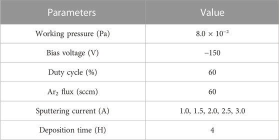
TABLE 1. Depositing parameters for the amorphous carbon films.
2.2 Characterization
The surface morphologies were characterized by a field emission scanning electron microscope (SEM S4800, Hitachi, Japan)) using an accelerating voltage of 8 KV. The cross-section morphologies of the amorphous carbon films were characterized by Focus ion beam scanning electron microscopy (FIB-SEM, Thermo scientific, Waltham, MA, United States). To improve the conductivity of the sample and reduce the charging effect, platinum was deposited for 180 s before the experiment. The chemical structures were determined by ATR-FTIR (cary660 + 620, Agilent, Santa Clara, CA, United States), and each spectrum was recorded with 32 repeated scans in the spectral range of 4000–400 cm−1. A Raman spectrometer (Renishaw invia Reflex, London, United Kingdom) with laser wavelength of 325 nm was used to characterize the bonding structure of the film. The chemical composition and biding states were analyzed by X-ray spectroscopy (XPS, AXISULTRA, Kratos, Manchester, United Kingdom) using Al Kα radiation as the excitation source. Under the continuous stiffness measurement mode, the nanoindenter with a Berkovich indenter was used to measure the hardness (H) and elastic modulus (E) of the amorphous carbon films. To reduce the experimental error, eight different locations on the sample surface were selected for measurement. The tribological properties of the amorphous carbon films were tested by reciprocating tribometer (UMT-3, Instruments, United States) in ambient air. All tribological measurements were performed under following conditions: the sliding distance of 5 mm, the sliding frequency of 5 Hz and the total test duration of 1,800 s. Two normal loads including 2 N and 8 N were used in tribological tests. In addition, the pair of grinding pairs was 316 L steel balls with a diameter of 6 mm. After the friction test, the field emission scanning electron microscope (SEM S4800, Hitachi, Japan) was used to observe the surface morphology of the wear track and the 316 L steel balls. The three-dimensional micrographs and the cross-section profiles of the worn track were measured by the scanning white-light interfering profilometer (UPLambda2, Rtec Instruments, United States) and the contact surface profilometer (Alpha - Step IQ, United States), respectively. Use the following formula to calculate the wear rate:
Where V is the wear volume, F is the normal load (2 N or 8 N) and S is the sliding distance.
3 Results and discussion
3.1 Microstructure
Raman spectroscopy was popularly used to study the structure of carbonaceous materials due to its sensitivity to the bonding structure and domain sizes (Yong et al., 2016). Different carbon materials have unique spectral characteristics, such as peak positions, full width at half maximum, and intensity ratios. The changes of peak position, FWHM and peak strength in Raman spectrum were important information for the analysis of chemical composition and structure of carbon films. Raman results of PI surfaces treated by carbon plasma with different graphite target currents are shown in Figure 1. After peak fitting in Gaussian deconvolution procedures, D peak at 1,420 cm−1 and G peak at 1,580 cm−1 were obtained in Figure 1A. The D peak is generated by the breathing mode of the sp2 sites in the six-fold rings, while the G peak is produced by stretching vibration of all pairs of sp2 carbon atoms in the rings and chains (Robertson, 2002; Cui et al., 2010). Theoretically, the intensity ratio of the D peak and the G peak (ID/IG) is closely related to the content of sp2 C-C and sp3 C-C in the system. Larger ID/IG values indicate the presence of more sp2 C-C in the amorphous carbon films. Table 2 presents the position and FWHM of the D and G peaks, as well as the ID/IG ratio of substrates treated by carbon plasma with different graphite target currents. With the increase of the graphite target current, the ID/IG ratio decreases first and then increases. The results show that the content of sp2 C-C in amorphous carbon films decreases first and then increases with the increase of the graphite target current. After Gaussian fitting, G peak widened and moved to lower wave number, which might be due to the increase of bond angle disorder in sp2 C-C or the increase of sp3 C-C content.
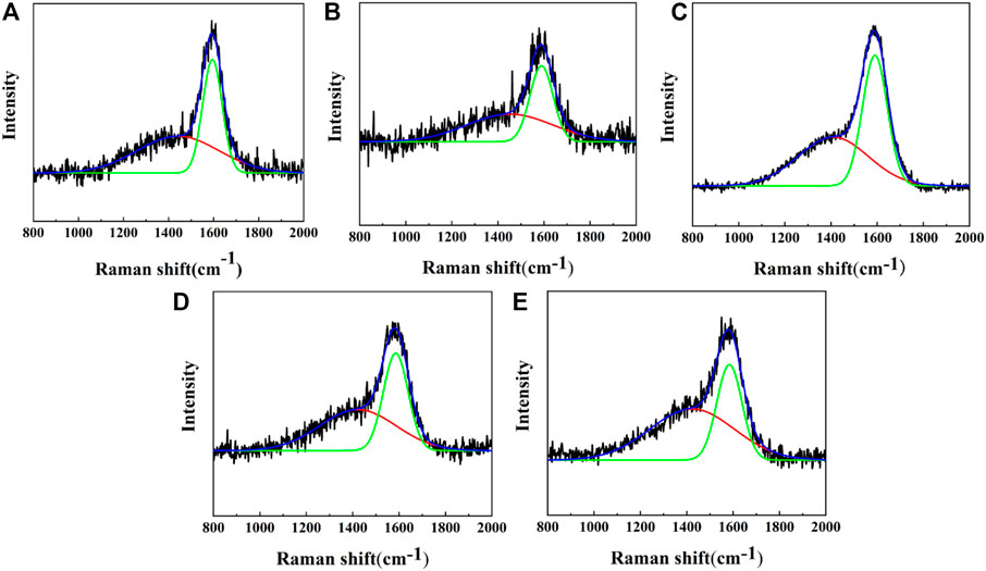
FIGURE 1. Raman results of PI surfaces treated by carbon plasma with different graphite target currents: (A) 1.0A; (B) 1.5A; (C) 2.0A; (D) 2.5A; (E) 3.0A.
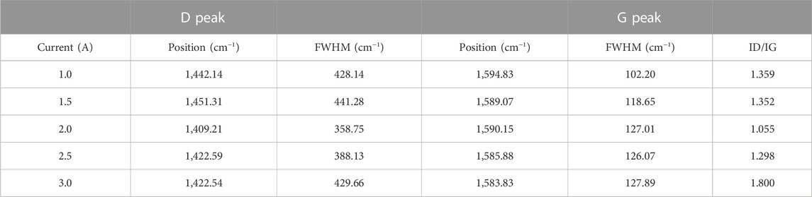
TABLE 2. The position, FHWM of the D peak and G peak, and ID/IG ratio of PI substrates treated with different sputtering currents.
X-ray photoelectron spectroscopy was used to analyze the elemental composition and chemical bond types of carbon films. Figure 2 shows the XPS spectra of PI substrates treated by carbon plasma with different graphite target currents. According to the Figure 2A, the XPS spectra for the amorphous carbon film showed the peaks of C 1s at 284.0 eV, O 1s at 532.0 eV. Using CasaXPS software, the C1s spectrum was fitted to four peaks at around 284.6 eV, 285.3 eV, 286.7 eV, and 288.6 eV, which are assigned to sp2 C–C, sp3 C–C, C–O and C=O (Dang et al., 2021; Wu et al., 2021), respectively, as shown in Figure 2B. As shown in Figure 2C, the content of sp2 C-C in the amorphous carbon film decreases first and then increases with the increase of graphite target current, which is consistent with the Raman results. According to the subplantation model of amorphous carbon film growth, the energy of incident carbon atoms is the key factor to determine the film structure. When the current of graphite target is low, the atoms with low energy cannot penetrate the surface and adhere to the substrate surface. When the current of graphite target increases, atoms with high energy penetrate the surface layer and inject into the sub surface, resulting in deformation and compressive stress of the film. The compressive stress will cause the diamond phase with the pressure and temperature in the film in the phase diagram, and finally the atomic clusters will stably form the sp3 C-C. When the current of graphite target continues to increase, the energy of incident ions will further increase, and the thermal peak effect of ion implantation will cause structural relaxation of the film and tend to sp2 C-C.
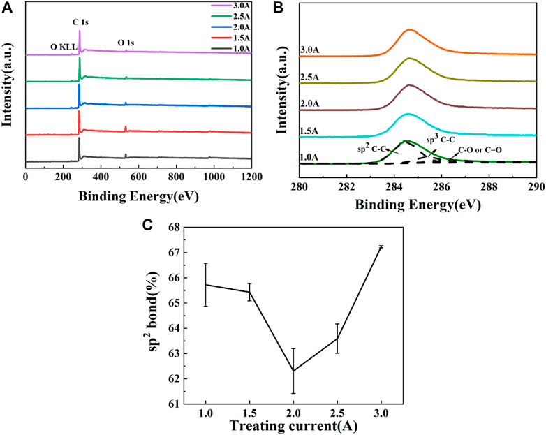
FIGURE 2. XPS of PI substrates treated by carbon plasma with different graphite target currents: (A) full spectra (B) C1s spectra (C) the content of sp2 bond.
Figure 3 shows the surface and cross-sectional morphologies of PI treated by carbon plasma with different graphite target currents. According to the surface morphologies, it could be seen that the surface of the amorphous carbon film presents an island structure with fragments in local areas. Carbon plasma adsorbed on the PI surface will diffuse, migrate, collide and form atomic clusters. When the number of atoms reaches a certain number, a stable nucleus will be formed. Amorphous carbon films will be grown on PI substrate in island growth mode (Maheswaran et al., 2011). The higher the current of graphite target, the more obvious the island structure. This is because the energy of carbon plasma increases with the increase of graphite current, which improves the mobility of particles on the surface and fills the gap between clusters. Seen from the cross-sectional morphologies, the thickness of amorphous carbon film fabricated with graphite target current 1.0, 1.5, 2.0, 2.5 and 3.0A were about 0.320 ± 0.015 um, 0.570 ± 0.010 um, 0.820 ± 0.010 um, 0.965 ± 0.010 um and 1.250 ± 0.050 um, respectively. With the increase of graphite target current, the thickness of the amorphous carbon film increases. It should be noted that there were hole defects at the interface between the film and the substrate when the graphite target current was 1.0 and 1.5 A. When the graphite target current increased to 2.0 A, the defect disappears. When the graphite target current further increased to 2.5 or 3.0 A, an obvious intermediate layer appeared between the surface of the PI and the amorphous carbon film. It seemed that the intermediate layer formed from the inner of PI which in situ transformed from surface microstructures of substrates. Carbon plasma may play an inductive role in it. Plasma bombardment helps to remove pollutants on the polymer surface, destroy molecular chains, increase etching and chemical functionalization (Bui et al., 2009; Boeva et al., 2017). Continuous plasma bombardment induces the transformation of organic carbon structure in PI into inorganic carbon structure in amorphous carbon films. Current is one of the most important parameters affecting the growth process. At low currents, the energy of carbon plasma is not enough, and the bombardment effect on the substrate is weak, mainly the deposition effect of the amorphous carbon film. The higher the sputtering current is, the higher the carbon plasma energy is. It is conducive to breaking the polymer chain and inducing the organic carbon structure in PI to change into an inorganic carbon structure. This induced transformation effect makes no structural mutation between the substrate and the film, which can effectively reduce the defects in the deposition process and improve the bonding strength between the film and the substrate.

FIGURE 3. Surface and cross-sectional morphologies of PI surface treated by carbon plasma with different graphite target currents: (A) 1.0 A; (B) 1.5 A; (C) 2.0 A; (D) 2.5 A; (E) 3.0 A.
Figure 4 shows the infrared spectrum curves of PI surface treated by carbon plasma with different graphite target currents. The main characteristic peaks of PI are 716, 1,364, 1,709 and 1,775 cm−1, respectively, which correspond to the bending vibration of C=O in the imide ring, the stretching vibration of C-N-C in the imide ring, and the symmetric and asymmetric stretching vibration of C=O in the imide ring (Li et al., 1998). In addition, compared with the original PI, the peak intensity of the samples treated by carbon plasma with different graphite target currents is weakened, and the peak location is shifted towards the lower wave number. It may be that the interaction between atoms in the conjugated system changes the density of the electron cloud, causing the absorption peak to redshift. After the graphite target current treatment, the intensity of the C-H stretching vibration absorption peak at 2,972 cm−1 was weakened until completely disappeared. The molecular chain on PI surface may be broken due to the bombardment effect of plasma.
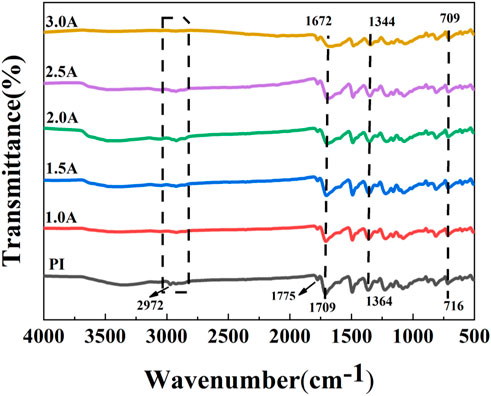
FIGURE 4. Fourier infrared spectroscopy of PI surface treated by carbon plasma with different graphite target currents.
In the magnetron sputtering system, the electrons in the magnetic field could collide with argon atoms, ionizing argon into ions and new electrons. Under the action of the electric field, argon ions are accelerated to the graphite target and bombard the target surface, generating carbon plasma rich in a large number of energetic particles including atoms, electrons and free radicals. The energy of the carbon plasma is related to the current of the graphite target. The higher the graphite target current is, the higher the carbon plasma energy is generated and the stronger the impact effect on PI surface is. The carbon plasma was easy to impact the fragile C-N, C-O-C, C-H bonds in the polyimide molecular chain, inducing active polymer chains with different molecular weights by randomly broken bonds. Under the continuous bombardment of carbon plasma, the active polymer chain segments were possible to overflow from the surface or subsurface of the polyimide matrix. Consequently, the cross-linking reactions between active polymer chains occurred. When the cross-linking reactions reached a certain degree, a three-dimensional network structure would be formed at the top of the polymer substrate, which contained new polymer carbonaceous structure different substrate and effectively inhibited the active polymer chain segments from continuing to spill out. Meantime, the active polymer chain reacted with carbon free radicals as well, forming composite structures consisting of inorganic chains and organic chains inside the three-dimensional network. After that, carbon plasma continuously interacted with each other on the fresh surface, then a pure amorphous carbon layer was formed by “epitaxial growth” on the surface of a mixed interlayer, i.e., the three-dimensional network at the top of PI substrate composed of the new polymer carbonaceous structure different to the substrate and the inorganic carbonaceous structure perhaps the amorphous carbon. This kind of mixed interlayer was in situ transformed from the inner of the polymer substrate by the treatment of carbon plasma, therefore it was called the in situ transition layer induced by carbon plasma. According to Figure 3, the in situ transition layers were observed when the graphite target current increased to 2.5 and 3.0 A. When the thickness of the amorphous carbon layer increased continuously, and the amorphous carbon layer further inhibited the active polymer chain segment from overflowing outward. Finally, the amorphous carbon films grown on the surface of PI substrate, containing an in situ transition layer and a pure amorphous carbon layer.
3.2 Mechanical properties
The bonding strength of the film and the substrate is an important factor determining the stability, service life and comprehensive performance of the film. The insufficient bonding strength will lead to wrinkling, cracking and even peeling of the film. Figure 5 shows the optical images of scratch tracks of PI surface by carbon plasma with different graphite target currents. When the loading force is small, there is no obvious transverse crack on the sample surface. With the increase of load, the surface of amorphous carbon film appears dense crack areas, but the film will not peel off from the substrate surface. In the figure, we have marked the position where the first transverse crack occurs perpendicular to the scratch direction. It can be found that the larger the graphite target currents are, the greater the coordinate value of this position is. In general, the critical load value Lc can be determined from the acoustic emission signal of hard coating cracking. Figure 6 shows the acoustic emission signal detected by the scratch test system. From the AE value of the acoustic emission signal, it can be determined that Lc is approximately 5.7 N and 7.5 N.
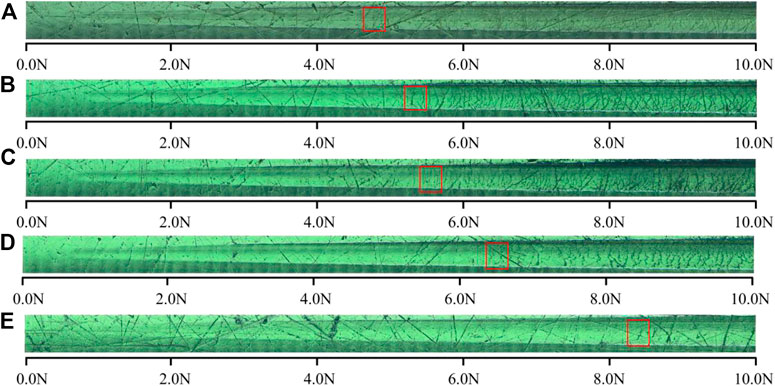
FIGURE 5. The optical images of scratch tracks of PI surface treated by carbon plasma with different graphite target currents: (A) 1.0 A (B) 1.5 A (C) 2.0 A (D) 2.5 A (E) 3.0 A.
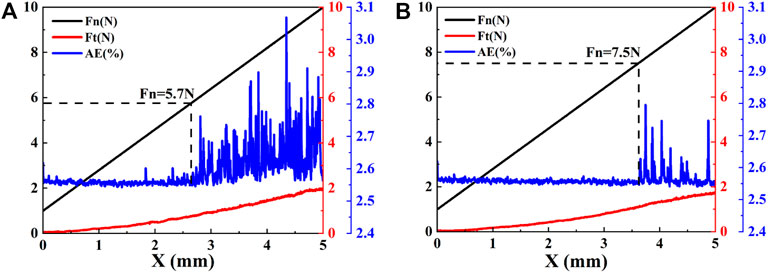
FIGURE 6. The scratch data of PI surface treated by carbon plasma with different graphite target currents: (A)2.5 A (B)3.0 A.
Hardness and elastic modulus are important parameters for evaluating the mechanical properties and wear resistance of thin films. The changes in microhardness (H), elastic modulus (E), H/E and H3/E2 of PI surface treated by carbon plasma with different graphite target currents are shown in Figure 7. The microhardness and elastic modulus increase with the increase of graphite target currents. The microhardness of the samples at 3.0A (4.778 GPa) becomes more than 34 times that of the original PI (0.138 GPa), and the elastic modulus of the samples (33.104 GPa) at this current becomes nearly 15 times that of the original PI (2.099 GPa). In the process of carbon plasma treatment, energy dissipation leads to cross-linking between adjacent polymer chains, forming a network structure. The graphite-like and carbon-rich amorphous structures in the network can improve the hardness and the elastic modulus. Theoretically, the values of H/E and H3/E2 are related to the durability and plastic deformation resistance of the film. The larger values of H/E and H3/E2 indicate that the samples have better bearing capacity and better wear resistance (Dang et al., 2016). As shown in the illustration, with the increase of sputtering current, the values of H/E and H3/E2 both increase first and then tend to be stable. From the point of view of wear resistance, there may be an optimal parameter within this current range, which is also the reason why the sample was not treated with a larger sputtering current in this study.
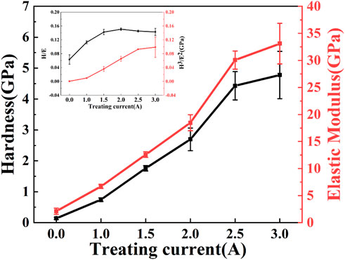
FIGURE 7. The microhardness and the elastic modulus of PI surface treated with different graphite target currents.
3.3 Tribological performance
Figure 8 shows the friction coefficient of the PI substrates treated with different graphite target currents sliding against 316 stainless steel balls in ambient air with a 2 N load. As shown in Figure 8A, the friction coefficient of the samples treated with carbon plasma is significantly lower than that of pristine PI, and the friction coefficient decreases with the increase of sputtering current. It is worth noting that the friction coefficients of the samples treated with 1.0 A, 1.5 A and 2.0 A currents gradually increased in the initial stage, and the curves showed obvious fluctuations after stabilization. For the samples treated with 2.5 A or 3.0 A current, after a short running-in period, the friction curve is relatively stable. To search the small differences of the friction behaviors, the average friction coefficient and the wear rate were calculated, as shown in Figure 8B, and the steady-state friction coefficients of the films are as follows: 0.5244 (PI), 0.4695 (1.0 A),0.4622 (1.5 A), 0.4426 (2.0 A), 0.2041 (2.5 A) and 0.1681 (3.0 A). The wear rate are about 1.88 × 10⁻⁶ mm3/Nm (PI), 6.22 × 10⁻⁶ mm3/Nm (1.0 A), 8.05 × 10⁻⁶ mm3/Nm (1.5 A), 7.88 × 10⁻⁶ mm3/Nm (2.0 A), 3.36 × 10⁻⁶ mm3/Nm (2.5 A), 2.06 × 10⁻⁶ mm3/Nm (3.0 A).

FIGURE 8. The friction coefficient of the PI substrates treated with different graphite target currents with a 2N load: (A) the friction coefficient curve (B) the average friction coefficient and the wear rate.
To further study the wear mechanism, we investigated the morphologies of the wear tracks and grinding balls. As shown in Figure 9, the narrow and dense furrows parallel to the friction direction appeared on the original PI surface after friction, and the middle sag is strip-like and the edge part is raised. In addition, the width of the wear track is the largest, and the grinding ball is adhered to the abrasive. The wear mechanism is the coexistence of abrasive wear and adhesive wear. The amorphous carbon films prepared at low current (1.0 A, 1.5 A or 2.0 A) also show gullies after friction, the spacing between gullies becomes larger, and many microcracks, local concave holes and spalling appear on the surface of the wear scars. The detached amorphous carbon film is sandwiched between the PI matrix and the matching ball to form three-body wear, which is extremely unstable and also explains the reason for the sharp fluctuation of the friction curve. Correspondingly, the detached amorphous carbon film was observed on the surface of the mill ball. The morphology of wear track shows that the amorphous carbon film has been severely worn during the friction process and has lost its protective effect on the PI surface. Figure 10 shows the 3D micrographs and the cross-section profiles of the wear tracks of the PI substrates treated with different graphite target currents. It can be observed that the wear depth of the failed amorphous carbon film increases from 1.903 um to 3.732 um, which is much higher than the wear depth of the original PI. This may be related to the hardness, shape and size of the abrasive. Generally speaking, the higher the hardness, the larger the size and the more irregular the shape of the abrasive, the greater the wear of the material. Hard and brittle films are more likely to form sharp and angular abrasives. Once the protective effect of the amorphous carbon film fails, the abrasives will continuously cut on the plastic surface, causing severe wear on the substrate. For samples treated with 2.5 A or 3.0 A current, the wear track is smooth and flat, the width of the wear track is significantly reduced, and there is almost no amorphous carbon film falling off on the grinding ball. The wear depth was also greatly reduced, which were 0.894 um and 0.708 um, respectively, which did not exceed the deposition thickness of the amorphous carbon film.
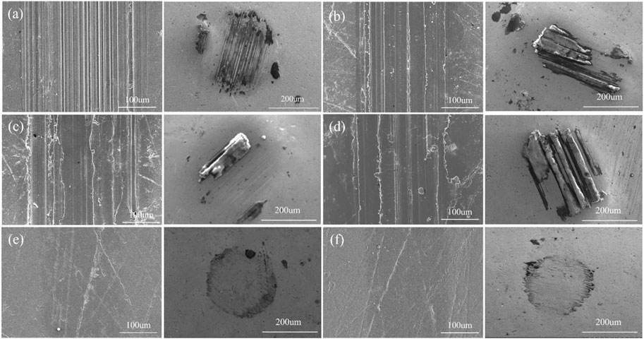
FIGURE 9. Wear tracks and wear scars of the PI substrates treated with different graphite target currents: (A) 0.0 A (B) 1.0 A (C) 1.5 A (D) 2.0 A (E)2.5 A (F) 3.0 A.
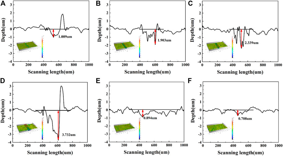
FIGURE 10. 3D micrographs and the cross-section profiles of the wear tracks of the PI substrates treated with different graphite target currents: (A) 0.0 A (B) 1.0 A (C) 1.5 A (D) 2.0 A (E) 2.5 A (F) 3.0 A.
To further explore the wear resistance of the samples treated with different currents, we increased the load to 8 N. As shown in Figure 11, the steady-state friction coefficients of the films are as follows: 0.3922 (PI), 0.4118 (2.5 A) and 0.1665 (3.0 A). The wear rates are about: 6.68 × 10⁻⁶ mm3/Nm (PI), 8.72 × 10⁻⁶ mm3/Nm (2.5 A), 1.08 × 10⁻⁶ mm3/Nm (3.0 A). As can be seen from the data in Figure 12, when the load increases, the wear depth and wear rate of PI and the samples treated with 2.5 A graphite target current increase greatly. The amorphous carbon films with sputtering current of 3.0 A show the best tribological properties in ambient air. For samples treated with 3.0 A current, the lower friction coefficient is due to the presence of is due to the presence of graphite-like microstructure, a transfer film on the surface of the ball and an in situ transition layer. Raman spectra show that higher sp2 C-C content and ID/IG value mean higher graphitization degree and effective solid lubrication, which is beneficial to reduce the friction coefficient and stabilize the friction process. Figure 13 shows the Raman spectra of the grinding ball with samples treated with 3.0 A current, indicating that the transfer layer on the wear scar is carbon film. At the same time, from the point of view of the bonding strength between hard film and soft substrate, plasma-induced in situ transition layer makes the bonding between amorphous carbon film and PI more tightly and more like a whole. It is the enhancement of bonding strength that promotes the realization of good tribological properties.
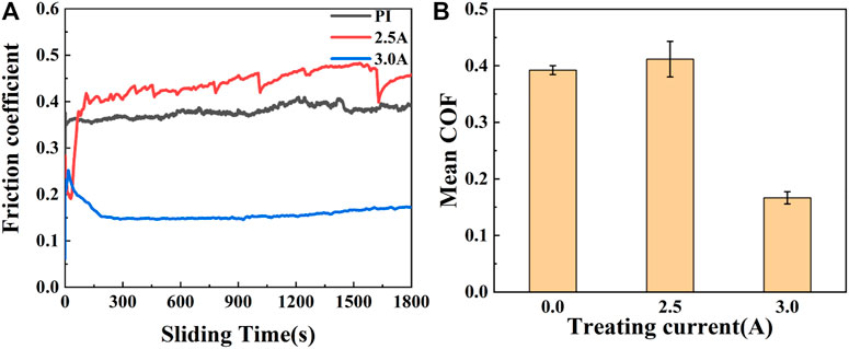
FIGURE 11. The friction coefficient of the PI substrates treated with different graphite target currents with loads of 8N: (A) the friction coefficient curve (B)the average friction coefficient and the wear rate.

FIGURE 12. The cross-section profiles of the wear tracks of the PI substrates treated with different graphite target currents: (A) 0.0 A (B) 2.5 A (C) 3.0 A.
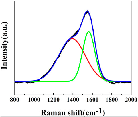
FIGURE 13. Raman spectra of the grinding ball with samples treated with 3.0 A current under 8 N.
4 Conclusion
The amorphous carbon films with in situ transition layer have been successfully prepared on PI surface by adjusting the sputtering current. The results show that the microstructure, chemical composition, mechanical properties and tribological properties of amorphous carbon films are highly dependent on the carbon plasma energy. With the increase of carbon plasma energy, the density and hardness of the films are improved, and the content of sp2 C-C also decreased first and then increased. The changes of microstructure, chemical composition and mechanical properties affect the tribological properties of the films. At the same time, the presence of the in situ transition layer makes the bonding between amorphous carbon film and PI more tightly and more like a whole. This structure is conducive to improving the integrated bearing capacity of the film and substrate. The amorphous carbon films deposited at 3.0 A exhibit low friction and wear and high load-carrying capacity in ambient air. On this basis, we also discussed the influence of carbon plasma energy on the in situ transition layer. The results show that carbon plasma plays two roles in the growth of amorphous carbon films, one is deposition effect, the other is induction effect. Sputtering current is the key factor affecting the in situ growth mechanism. At low current, the energy of carbon plasma is small, and the induction effect is weak. When the sputtering current exceeds a certain value, the carbon plasma can induce the formation of an in situ transition layer on the PI surface, which is accompanied by the deposition effect of the film.
Data availability statement
The original contributions presented in the study are included in the article/supplementary material, further inquiries can be directed to the corresponding author.
Author contributions
YuW: Conceptualization, Methodology, Validation, Investigation, Data curation, writing—original draft, writing—review & editing. YoW: Resources, Supervision, Project administration, Funding acquisition, writing—review & editing. YL: Investigation.
Acknowledgments
The authors are thankful for the financial support of the National Natural Science Foundation of China (Grant No. 51975563), the Science and Technology Service Network Initiative CAS-Dongguan (Grant No. 20201600200092) and the Key R & D Programs in Zhejiang Province (Grant No. 2020C03102).
Conflict of interest
The authors declare that the research was conducted in the absence of any commercial or financial relationships that could be construed as a potential conflict of interest.
Publisher’s note
All claims expressed in this article are solely those of the authors and do not necessarily represent those of their affiliated organizations, or those of the publisher, the editors and the reviewers. Any product that may be evaluated in this article, or claim that may be made by its manufacturer, is not guaranteed or endorsed by the publisher.
References
Abbas, G. A., Roy, S. S., Papakonstantinou, P., and McLaughlin, J. A. (2005). Structural investigation and gas barrier performance of diamond-like carbon based films on polymer substrates. Carbon 43, 303–309. doi:10.1016/j.carbon.2004.09.016
Boeva, Z. A., Catena, A., Höfler, L., Wehner, S., Fischer, C. B., and Lindfors, T. (2017). Improved water barrier properties of polylactic acid films with an amorphous hydrogenated carbon (a-C:H) coating. Carbon 120, 157–164. doi:10.1016/j.carbon.2017.05.005
Bui, X. L., Pei, Y. T., Mulder, E. D. G., and De Hosson, J. Th. M. (2009). Adhesion improvement of hydrogenated diamond-like carbon thin films by pre-deposition plasma treatment of rubber substrate. Surf. Coatings Technol. 203, 1964–1970. doi:10.1016/j.surfcoat.2009.01.027
Bull, S., Mccabe, A., and Jones, A. (1994). Mechanical and tribological performance of ion-beam deposited diamond-like carbon on polymers. Surf. Coat. Technol. 64, 87–91. doi:10.1016/S0257-8972(09)90008-1
Cai, J. B., Wang, X. L., Bai, W. Q., Zhao, X. Y., Wang, T. Q., and Tu, J. P. (2013). Bias-graded deposition and tribological properties of Ti-contained a-C gradient composite film on Ti6Al4V alloy. Appl. Surf. Sci. 279, 450–457. doi:10.1016/j.apsusc.2013.04.136
Casiraghi, C., Robertson, J., and Ferrari, A. C. (2007). Diamond-like carbon for data and beer storage. Mater. Today 10, 44–53. doi:10.1016/S1369-7021(06)71791-6
Catena, A., Agnello, S., Cannas, M., Gelardi, F. M., Wehner, S., and Fischer, C. B. (2017). Evolution of the sp2 content and revealed multilayer growth of amorphous hydrogenated carbon (a-C:H) films on selected thermoplastic materials. Carbon 117, 351–359. doi:10.1016/j.carbon.2017.02.093
Catena, A., Agnello, S., Rösken, L. M., Bergen, H., Recktenwald, E., Bernsmann, F., et al. (2016a). Characteristics of industrially manufactured amorphous hydrogenated carbon (a-C:H) depositions on high-density polyethylene. Carbon 96, 661–671. doi:10.1016/j.carbon.2015.09.101
Catena, A., Guo, Q., Kunze, M. R., Agnello, S., Gelardi, F. M., Wehner, S., et al. (2016b). Morphological and chemical evolution of gradually deposited diamond-like carbon films on polyethylene terephthalate: From subplantation Processes to structural reorganization by intrinsic stress release phenomena. ACS Appl. Mater. Interfaces 8, 10636–10646. doi:10.1021/acsami.6b02113
Cui, W. G., Lai, Q. B., Zhang, L., and Wang, F. M. (2010). Quantitative measurements of sp3 content in DLC films with Raman spectroscopy. Surf. Coatings Technol. 205, 1995–1999. doi:10.1016/j.surfcoat.2010.08.093
Cuong, N. K., Tahara, M., Yamauchi, N., and Sone, T. (2003). Diamond-like carbon films deposited on polymers by plasma-enhanced chemical vapor deposition. Surf. Coatings Technol. 174–175, 1024–1028. doi:10.1016/S0257-8972(03)00360-8
Dang, C., Li, J., Wang, Y., and Chen, J. (2016). Structure, mechanical and tribological properties of self-toughening TiSiN/Ag multilayer coatings on Ti6Al4V prepared by arc ion plating. Appl. Surf. Sci. 386, 224–233. doi:10.1016/j.apsusc.2016.06.024
Dang, R., Ma, L., Zhou, S., Pan, D., and Xia, B. (2021). Achieving good protection on ultra-high molecular weight polythene by in situ growth of amorphous carbon film. Coatings 11, 584. doi:10.3390/coatings11050584
Ding, X., Tay, B. K., Lau, S. P., Zhang, P., and Zeng, X. T. (2002). Structural and mechanical properties of Ti-containing diamond-like carbon films deposited by filtered cathodic vacuum arc. Thin Solid Films 408, 183–187. doi:10.1016/S0040-6090(02)00145-1
Ferrari, A. C., and Robertson, J. (2000). Interpretation of Raman spectra of disordered and amorphous carbon. Phys. Rev. B 61, 14095–14107. doi:10.1103/PhysRevB.61.14095
Freeman, M., and Harding, D. (1994). Plasma-enhanced deposition of diamond-like carbon-films on high-temperature tolerant polymers. J. Polym. Sci. Pt. B-Polym. Phys. 32, 1377–1388. doi:10.1002/polb.1994.090320809
Guan, W., Wang, Y., Fischer, C. B., Wehner, S., Wang, Z., Li, J., et al. (2020). Novel strategy to improve the tribological property of polymer: In-situ growing amorphous carbon coating on the surface. Appl. Surf. Sci. 505, 144626. doi:10.1016/j.apsusc.2019.144626
Guo, Y.-B., and Chau-Nan Hong, F. (2003). Adhesion improvements for diamond-like carbon films on polycarbonate and polymethylmethacrylate substrates by ion plating with inductively coupled plasma. Diam. Relat. Mater. 12, 946–952. doi:10.1016/S0925-9635(02)00320-5
He, F. F., Bai, W. Q., Li, L. L., Wang, X. L., Xie, Y. J., Jin, G., et al. (2016). Enhancement of adhesion by a transition layer: Deposition of a-C film on ultrahigh molecular weight polyethylene (UHMWPE) by magnetron sputtering. Appl. Surf. Sci. 364, 280–287. doi:10.1016/j.apsusc.2015.12.150
Khatir, S., Hirose, A., and Xiao, C. (2014). Coating diamond-like carbon films on polymer substrates by inductively coupled plasma assisted sputtering. Surf. Coatings Technol. 253, 96–99. doi:10.1016/j.surfcoat.2014.05.020
Lee, J.-A., Lin, C.-R., Pan, P.-C., Liu, C.-W., and Sun, A. Y. T. (2020). Dramatically enhanced mechanical properties of diamond-like carbon films on polymer substrate for flexible display devices via argon plasma pretreatment. Chem. Phys. 529, 110551. doi:10.1016/j.chemphys.2019.110551
Li, W. S., Shen, Z. X., Zheng, J. Z., and Tang, S. H. (1998). FT-IR study of the imidization process of photosensitive polyimide PMDA/ODA. Appl. Spectrosc. 52, 985–989. doi:10.1366/0003702981944625
Love, C. A., Cook, R. B., Harvey, T. J., Dearnley, P. A., and Wood, R. J. K. (2013). Diamond like carbon coatings for potential application in biological implants—A review. Tribol. Int. 63, 141–150. doi:10.1016/j.triboint.2012.09.006
Maheswaran, R., Ramaswamy, S., Thiruvadigal, D. J., and Gopalakrishnan, C. (2011). Systematic study of various stages during the growth process of diamond-like carbon film by atomic force microscopy. J. Non-Crystalline Solids 357, 1710–1715. doi:10.1016/j.jnoncrysol.2011.02.012
Mccabe, A., Jones, A., and Bull, S. (1994). Mechanical-properties of ion-beam deposited diamond-like carbon on polymers. Diam. Relat. Mat. 3, 205–209. doi:10.1016/0925-9635(94)90081-7
Michler, T., Grischke, M., Bewilogua, K., and Dimigen, H. (1998). Properties of duplex coatings prepared by plasma nitriding and PVD Ti–C:H deposition on X20Cr13 ferritic stainless steel. Thin Solid Films 322, 206–212. doi:10.1016/S0040-6090(97)00959-0
Nakahigashi, T., Tanaka, Y., Miyake, K., and Oohara, H. (2004). Properties of flexible DLC film deposited by amplitude-modulated RF P-CVD. Tribol. Int. 37, 907–912. doi:10.1016/j.triboint.2004.07.007
Puertolas, J. A., Martinez-Nogues, V., Martinez-Morlanes, M. J., Mariscal, M. D., Medel, F. J., Lopez-Santos, C., et al. (2010). Improved wear performance of ultra high molecular weight polyethylene coated with hydrogenated diamond like carbon. Wear 269, 458–465. doi:10.1016/j.wear.2010.04.033
Raffaele-Addamo, A., Riccardi, C., Selli, E., Barni, R., Piselli, M., Poletti, G., et al. (2003). Characterization of plasma processing for polymers. Surf. Coatings Technol. 174–175, 886–890. doi:10.1016/S0257-8972(03)00364-5
Ray, S. C., Mukherjee, D., Sarma, S., Bhattacharya, G., Mathur, A., Roy, S. S., et al. (2017). Functional diamond like carbon (DLC) coatings on polymer for improved gas barrier performance. Diam. Relat. Mat. 80, 59–63. doi:10.1016/j.diamond.2017.09.001
Robertson, J. (2002). Diamond-like amorphous carbon. Mater. Sci. Eng. R Rep. 37, 129–281. doi:10.1016/S0927-796X(02)00005-0
Son, P. K., Park, J. H., Jo, B. K., Lee, S. P., Lee, J. H., Kim, J. C., et al. (2009). Anisotropy and Raman absorption of the polyimide surface irradiated by the ion beam for liquid crystal alignment. Thin Solid Films 517, 1803–1806. doi:10.1016/j.tsf.2008.09.084
Su, Y., Wang, Y., Wang, C., Li, J., Guan, W., Guo, W., et al. (2021). In-situ growing amorphous carbon film with attractive mechanical and tribological adaptability on PEEK via continuous plasma-induced process. Vacuum 187, 110147. doi:10.1016/j.vacuum.2021.110147
Voevodin, A. A., Capano, M. A., Laube, S. J. P., Donley, M. S., and Zabinski, J. S. (1997). Design of a Ti/TiC/DLC functionally gradient coating based on studies of structural transitions in Ti–C thin films. Thin Solid Films 298, 107–115. doi:10.1016/S0040-6090(96)09145-6
Wang, P., Wang, X., Xu, T., Liu, W., and Zhang, J. (2007). Comparing internal stress in diamond-like carbon films with different structure. Thin Solid Films 515, 6899–6903. doi:10.1016/j.tsf.2007.02.069
Wang, Y., Li, Y., Wang, Y., Dang, R., Wang, C., and Guo, W. (2022). Fabrication and performance of flexible a-C films on terylene. Vacuum 196, 110766. doi:10.1016/j.vacuum.2021.110766
Wu, Y., Zhao, W., Lu, Z., and Wang, L. (2021). Fluorinated graphene film for corrosion control on copper: Experimental and theoretical studies. Carbon 179, 445–457. doi:10.1016/j.carbon.2021.04.040
Yong, Q.-S., Ma, G.-Z., Wang, H.-D., Chen, S.-Y., and Xu, B.-S. (2016). Structure and properties of GLC films deposited by PEMS. Surf. Eng. 32, 853–860. doi:10.1080/02670844.2016.1190138
Zhang, J., Zhao, H., Ji, T., Wu, G.-L., and Kou, K. (2012). Microhardness and tribological properties of polyimide composites modified by 200keV Ar ion implantation. Surf. Coatings Technol. 213, 21–25. doi:10.1016/j.surfcoat.2012.10.005
Keywords: polyimide, a-C film, in situ transformation, tribological performance, carbon plasma energy
Citation: Wu Y, Wang Y and Li Y (2023) Combining the good tribological properties with the high adhesion strength of the amorphous carbon films in situ grown on PI. Front. Mater. 10:1138854. doi: 10.3389/fmats.2023.1138854
Received: 06 January 2023; Accepted: 10 February 2023;
Published: 20 February 2023.
Edited by:
Guosong Wu, Hohai University, ChinaReviewed by:
Gennady G. Bondarenko, National Research University Higher School of Economics, RussiaKamalan Kirubaharan Amirtharaj Mosas, Alexander Dubcek University in Trencin, Slovakia
Copyright © 2023 Wu, Wang and Li. This is an open-access article distributed under the terms of the Creative Commons Attribution License (CC BY). The use, distribution or reproduction in other forums is permitted, provided the original author(s) and the copyright owner(s) are credited and that the original publication in this journal is cited, in accordance with accepted academic practice. No use, distribution or reproduction is permitted which does not comply with these terms.
*Correspondence: Yongxin Wang, eXh3YW5nQG5pbXRlLmFjLmNu