 Young T. Choi
 Byungseok Yoo†
 Norman M. Wereley
- Department of Aerospace Engineering, University of Maryland, College Park, MD, United States
Emerging additive manufacturing (or 3D printing) can be advantageous for developing magnetorheological fluid (MRF)-based vibration isolators (MRVIs) because their designs can be easily and efficiently customized and also in-situ fabrication and repairing can be possible. In this study, a simple and compact adaptive MRVI was fabricated by using a 3D printing method. A masked stereolithography (MSLA) 3D printer was used for the fabrication of the rubber bellow and plastic lid parts of the MRVI. The electromagnet was mounted onto the lid, the reservoir was filled with an MRF, and the lid was simply assembled with the reservoir using a 3D-printed large thread without traditionally machined components. Using a material testing machine, the damper forces of the 3D-printed MRVI were measured under a constant velocity loading condition for different magnetic fields. From these tests, the magnetic field-controllable performances of the MRVI such as the MR yield force, the dynamic force range, the dissipated energy, and the secant stiffness were obtained. For the evaluation of the long-term performance reliability of the MRVI due to the MRF sedimentation, its magnetic field-controllable performances were tracked for 156 days with the variable testing intervals. Finally, the feasibility of the 3D-printed MRVI was experimentally confirmed.
1 Introduction
Recent increased demands for human comfort, safety, and health have driven vibration isolation into becoming very essential design factor for developing engineering devices and systems used both in daily life and industries. Especially, in aerospace and construction industries, many devices and systems are inevitably operated in harsh vibration environments and thus must be designed to survive high levels of vibration. An effective vibration isolation strategy is to isolate payloads and occupants from vibration sources by installing vibration isolators (VIs) into the vibration transmission paths. There are mainly three types of VIs: passive, semi-active (or adaptive), and active methods. Passive VIs such as rubber and hydraulic VIs are the most common and have been widely used in the industries because of simple configuration, ease of installation, and low cost (Kaul, 2021). But, passive VIs have limited vibration isolation performance because they can be only tuned to a specific vibration spectrum. If the design point shifts, passive VIs rapidly lose their vibration isolation effectiveness. In contrast, adaptive VIs (York et al., 2016; Priyandoko et al., 2021; Choi and Wereley, 2022; Shen et al., 2022) using magnetorheological fluids (MRFs) and magnetorheological elastomers (MREs) can continuously adapt to changing vibration spectra by adjusting the magnetic field with an appropriate control algorithm. Active VIs (Wang et al., 2022; Yang et al., 2022) using electromagnets and piezoelectric materials have been also developed to cope with such changing vibration spectra. Since active VIs provide external energies to a target vibration system, they can cancel the vibration by generating an opposite force. Thus, for achieving better vibration isolation performance, active VIs require higher power consumption, delicate control algorithms, and relatively expensive sensors. But, different from active VIs, adaptive VIs have low power consumption, less expense, and no control instability.
Typically, MRF-based vibration isolators (MRVIs) have been configured by injecting an MRF into the reservoir enclosed by a metal cylinder and a rubber top part (Brigley et al., 2008; Brigley et al., 2007) or a movable metal piston with the rod (Choi et al., 2005). Traditional fabrication methods using subtractive manufacturing and injection rubber molding have been used to develop MRVIs. But, these traditional fabrication methods are economical only when large numbers are produced, which precludes customizing VIs for a specific available jitter space, natural frequency, or static displacement. Recently, the advent of additive manufacturing (i.e., 3D printing) can open a new approach for developing MRVIs. 3D printing is a computer-controlled manufacturing process that creates physical objects by stacking successive layers of material from digital information. Thus, 3D printing can be advantageous for developing MRVIs because their designs can be easily and efficiently customized, and also in-situ fabrication and repairing can be possible. But, the majority of 3D printing studies (Wang et al., 2018; Bond et al., 2020; Dunaj et al., 2020; Ude, 2020; Zolfagharian et al., 2022) of VIs reported so far have been focused on developing soft plastic-based passive VIs for structural damping, which cannot contain an operating hydraulic fluid and thus have low damping capability. A study of 3D-printed VIs that can produce a substantial adaptive damping range such as hydraulic VIs and MRVIs is seldom found in reported literature. Therefore, in this study, a 3D printing technique was used to construct an adaptive MRVI and its magnetic field-controllable performances were experimentally evaluated. Using a material testing machine, a single constant rate loading test of the 3D-printed MRVI under different magnetic fields was conducted and the force-displacement curves were experimentally obtained. Based on the measured data, the magnetic field-controllable performances of the MRVI such as the MR yield force, the dynamic force range, the dissipated energy, and the secant stiffness were determined. For the evaluation of the long-term performance reliability of the MRVI due to the MRF sedimentation, its magnetic field-controllable performances were tracked for 156 days with the variable testing intervals. Finally, the feasibility of the adaptive 3D-printed MRVI was experimentally confirmed.
2 Adaptive 3D-Printed MRVI
Figure 1 presents the schematic of the 3D-printed MRVI proposed in this study. The MRVI consisted of a rubber bellow, a plastic lid, an electromagnet (i.e., electromagnetic coil with the ferromagnetic bobbin), and an MRF. The electromagnet was attached to the top plastic lid using an M3 bolt. The bottom rubber bellow works as the container of an MRF and its wall can contract or expand to accommodate the vertical motion during vibration. The top lid was simply assembled with the bottom rubber bellow using a 3D-printed large thread without traditionally machined components. The total size of the MRVI was compact and can be applied to the vibration isolation of avionics or small-sized precision devices. The working fluid mode of this MRVI is squeeze-mode and thus an MRF was only filled so that the bottom portion of the electromagnet keeps being sufficiently submerged in the fluid during the vertical motion. The initial vertical fluid gap between the bottom of the electromagnet and the rubber bellow was 1 mm and the initial radial gap was 2 mm. When the electromagnet is moved by the vertical vibration, the MRF pushed by the electromagnet will be squeezed out from the vertical flow gap. Such a fluid flow produces a viscous damper force in the absence of a magnetic field. But, when the electromagnet is activated by an applied current, the MRF can make particle chains or columns at the vertical flow gap along the magnetic flux lines produced by the electromagnet. Such particle chains resist the squeezed fluid flow and cause the MRVI to produce additional MR yield force in the presence of a magnetic field. Also, this MR yield force can be continuously and rapidly controlled by a current input.
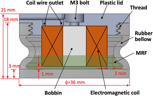
FIGURE 1. Schematic of the 3D-printed MRVI.
Figure 2 presents the photograph of the fabricated 3D-printed MRVI. The rubber bellow and the plastic lid were rapidly fabricated by using a masked stereolithography (MSLA) 3D printer (Elegoo, Mars 2 Pro, 405 nm UV (ultraviolet) light source). The top lid material was a hard (84D Shore hardness) UV photopolymer rapid resin (Elegoo, standard resin), but the rubber bellow material was an elastic (50–60A Shore hardness) UV photoresin (Resione, F80) so as to sufficiently accumulate the vertical motion. It is worth noting that many flexible photoresin-printed parts show hard rubber characteristics with low flexibility and slow rebound at room temperature. Such rubber characteristics are improved when the operating temperature becomes above 35°C. But, the F80 material has low-temperature resistance, fast rebound, and good flexibility. Thus, the F80-based rubber bellow behaves like a general silicone rubber material over the operating temperature range of 20°C–35°C, and can remain flexible even at temperatures as cold as 10°C, but begins to soften at temperatures above
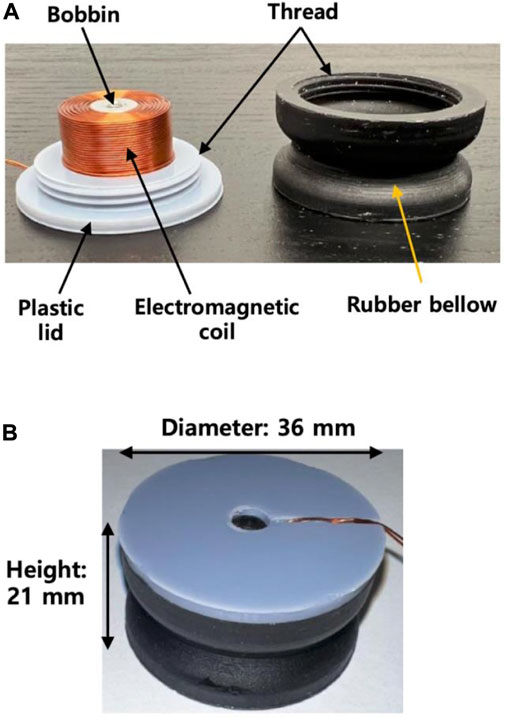
FIGURE 2. Photograph of the fabricated 3D-printed MRVI. (A) Parts. (B) Assembly.
3 Experimental
3.1 Testing setup
Figure 3 presents the experimental setup for the damper force measurement of the 3D-printed MRVI. For these tests, Instron material testing machine (DynaMight 8841) was used. The 3D-printed MRVI was placed between the top and bottom discs. The bottom steel disc was fixed to the stationary load cell and the top non-steel (aluminum) disc was connected to the hydraulic actuator of the testing machine. By using the top disc, the MRVI was compressed by 0.8 mm and was returned back to the initial position with a constant speed of 0.5 mm/s. At this time, the current input applied to the MRVI was varied from 0 to 1.5 A with an increment of 0.25 A. Here, 1.5 A was selected by a maximum current sufficient not to burn out the coil wire during testing. On the other hand, when the top disc of the MRVI was compressed by the hydraulic actuator of the Instron material testing machine, the MRF was squeezed out from the fluid gaps and produced a resisting force. This resisting force was transmitted to the bottom disk and the load cell connected to the bottom disc measured the transmitted resisting force.
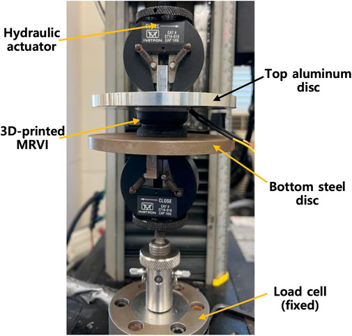
FIGURE 3. Experimental setup for the damper force measurement of the 3D-printed MRVI (the bottom steel disc configuration case).
3.2 Results
Figure 4 presents the measured magnetic field at the bobbin center of the 3D-printed MRVI. In this case, two different measurement configurations were considered: one is the MRVI between the top non-steel disc and the bottom steel disc (refer to Figure 3) and the other is the MRVI between the top and bottom non-steel discs. The magnetic fields at the bobbin center of the MRVI with respect to the current inputs were measured by using the gauss/teslameter (F.W. Bell, 5080). As seen in this figure, the magnetic field curve behaviors for both configurations were almost the same, which were almost linearly proportional to the applied current input up to 1.5 A. But, the bottom steel disc configuration case showed a 21% larger magnetic field magnitude at 1.5 A than the bottom non-steel disc configuration case because the bottom steel disc worked as the magnetic return guide for the electromagnet inside the MRVI. Thus, the bottom steel disc configuration was used for the damper force testing of the 3D-printed MRVI in this study.
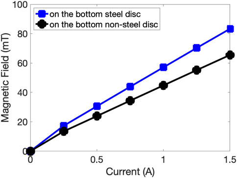
FIGURE 4. Measured magnetic field at the bobbin center of the 3D-printed MRVI.
Figure 5 presents the magnetic field-controllable performances of the 3D-printed MRVI at the initial testing day. In this case, the damper force of the MRVI was measured right away after the MRF was filled into the MRVI. As seen in Figure 5A, both the damper force magnitudes and hysteretic loops of the MRVI increased as the applied current increased. The increase in the damper force magnitude physically implies the increased stiffness of the MRVI, and the increased area of the hysteretic loop means the increased damping capability of the MRVI. The maximum damper force of the MRVI at the initial testing day was Fd,on = 53 N at a current input of 1.5 A and a displacement of 0.8 mm. Here, Fd,on is the field-on damper force. The MR yield force in the compression direction of the MRVI with respect to applied current inputs was presented in Figure 5B. Here, the MR yield force, FMR, was defined by
where, Fd,off is the field-off (i.e., viscous) damper force of the MRVI. The MR yield force, FMR, physically implies the additional damper force due to the yield stress of MRFs. As seen in this figure, the MR yield force continuously increased with the applied current input and was also strongly dependent on the displacement. Since the vertical flow gap between the bottom of the electromagnet and the rubber bellow of the MRVI decreased with the increased displacement, the MR yield force significantly increased as the displacement increased. The maximum MR yield force of the MRVI at the initial testing day was FMR = 40 N at a current input of 1.5 A. The dynamic range in the compression direction of the MRVI was presented in Figure 5C. Here, the dynamic range, DR, was the force ratio defined by
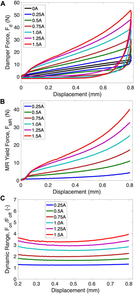
FIGURE 5. Magnetic field-controllable performances of the 3D-printed MRVI at the initial testing day. (A) Fd. (B) FMR in compression direction. (C) DR in compression direction.
The dynamic range of the MRVI in Figure 5C also continuously increased with the increased applied current input. But, different from the MR yield force behavior in Figure 5B, the dynamic range was much less dependent on the displacement. The maximum dynamic range of the MRVI at the onset of initial testing occurred at around 0.8 mm, that was DR = 4.0 at a current input of 1.5 A. By considering the typical desired dynamic range of many MRVIs (that is DR ≥ 2), such a DR = 4.0 implies that the 3D-printed MRVI used in this study can produce a sufficiently large controllable damper force.
Figure 6 presents the magnetic field-controllable performances of the 3D-printed MRVI after 156 days. In this case, 156 days do not mean the downtime of the MRVI but the elapsed time of the MRF after being filled in the MRVI. During the elapsed time of 156 days, the downtime was varied and the maximum downtime was 35 days. It should be noted that, once the MRF was filled in the MRVI, the sedimentation process of the Fe particles in the MRF started because of the significant density difference between the Fe particles (about 7.9 g mL−1) and the carrier fluid (about 1 g mL−1). Generally, the sedimentation of fluids can be evaluated by the particle settling velocity, and the particle settling velocity is inversely proportional to the particle concentration because of the hindering of the particles. Based on our previous MRF sedimentation studies (Choi et al., 2016; Chambers and Wereley, 2017; Wen et al., 2019), the sedimentation of the MRF (35 vol% Fe particles) used in this study was expected to be low since the particle settling velocity of an MRF with over 25 vol% Fe particles became significantly low. Compared with the results at the initial testing day in Figure 5, both the damper force magnitudes and hysteretic loops of the MRVI significantly increased after 156 days. This phenomenon results from the fact that Fe particles of the MRF settled down toward the bottom of the MRVI by the sedimentation process. This may make the effective flow gap of the MRVI smaller and thus both the field-off and field-on damper forces increased after 156 days. But, the increase in the field-on damper force of the MRVI due to the fluid sedimentation was larger than the increase in its field-off damper force. It is also well known that MRF sedimentation tends to reduce both the field-off and field-on performances of typical MRF-based dampers and devices operating by flow-mode (Zhang et al., 2019; Aruna et al., 2020) or shear-mode (Thakur and Sarkar, 2021) because the effective particle concentration of the MRFs goes down. But, interestingly, the squeeze-mode design proposed in this study improved the magnetic field-controllable performances of the MRVI against the MRF sedimentation rather than deteriorated them. The maximum damper force of the MRVI after 156 days became Fd,on = 112 N at a current input of 1.5 A and a displacement of 0.8 mm. Thus, the maximum MR yield force of the MRVI became FMR = 89 N at a current input of 1.5 A, which was about 122% larger than that at the initial test day. Also, the maximum dynamic range of the MRVI became DR = 4.8 at a current input of 1.5 A after 156 days, which was 20% larger than that at the initial test day.
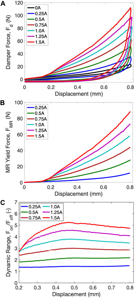
FIGURE 6. Magnetic field-controllable performances of the 3D-printed MRVI after 156 days. (A) Fd. (B) FMR in compression direction. (C) DR in compression direction.
Figure 7 presents the long-term history of the magnetic field-controllable performances of the 3D-printed MRVI for 156 days. In this figure, the dissipated energy, Wd was determined by
Here, x is the displacement. The dissipated energy, Wd implies the damping capability of the MRVI. Also, to evaluate the stiffness increment of the MRVI, the secant stiffness, Ks, was calculated at the maximum displacement, xmax, during loading as follows:
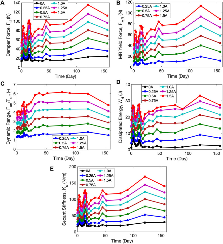
FIGURE 7. Long-term history of the magnetic field-controllable performances of the 3D-printed MRVI. (A) Fd. (B) FMR. (C) DR. (D) Wd. (E) Ks.
The secant stiffness evaluation is a linearization technique to approximate the non-linear behavior with a quasi-linear elastic model. The secant stiffness implies the quantity of the resistance at a displacement. The testing intervals (i.e., downtimes) were varied. From the initial test day to the 17th day, the testing interval was 1 day. The longest testing interval was 35 days at the 156th day. As seen in this figure, the magnetic field-controllable performances of the MRVI considerably fluctuated with the time when the testing interval was 1 day. This may imply that the displacement applied to the MRVI at the testing interval of 1 day could remix the MRF to a certain level and thus the effective flow gap size of the MRVI could also fluctuate. But, when the testing interval was longer than 10 days, its magnetic field-controllable performances were continuously improved until 121 days. After 121 days, the controllable performance started to decrease. The maximum damper force and MR yield force of the MRVI occurred at 121 days, those were Fd,on = 135 N and FMR = 113 N at a current input of 1.5 A. The maximum secant stiffness of the MRVI also occurred at 121 days. At the initial day, the secant stiffness was Ks,off = 17 N/m at no current input and Ks,on = 67 N/m at a current input of 1.5 A. After 121 days, the secant stiffness became Ks,off = 28 N at no current input and Ks,on = 169 N/m at a current input.
It should be noted that the fluctuation in the damper performances of the MRVI will be not desirable if the MRVI will be used as a passive actuator without a control algorithm. But, if this MRVI will be used as an adaptive actuator with a feedback control algorithm, such a fluctuation may be not an issue because the control algorithm will compensate for the performance variation. Instead, their performance deterioration by the sedimentation will be more problematic because the actuator cannot produce the desired damper force determined by the control algorithm.
Figure 8 presents the power consumption of the 3D-printed MRVI. As expected, the power consumption increased exponentially as the current input. But, the maximum power consumption of the adaptive 3D-printed MRVI was as small as 10.5 W at a current input of 1.5 A.
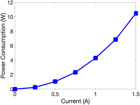
FIGURE 8. Power consumption of the 3D-printed MRVI.
4 Conclusion
The design and performance of an adaptive 3D-printed magnetorheological fluid (MRF)-based vibration isolator (MRVI) were presented in this study. To this end, a simple and compact adaptive MRVI design was proposed and successfully fabricated by using a masked stereolithography (MSLA) 3D printer. Different from previously reported studies on 3D-printed VIs, the 3D-printed MRVI in this study could contain an MRF and be operated under the squeeze fluid mode where the MRF was squeezed out from the fluid gaps. Using the Instron material testing machine, the damper forces of the 3D-printed MRVI with respect to applied current inputs were measured during loading-unloading compression motions. From the measured damper forces, the magnetic field-controllable performances of the 3D-printed MRVI such as MR yield force, dynamic force range, dissipated energy, and secant stiffness were experimentally presented. At the initial testing day, the damper force of the 3D-printed MRVI increased from Fd,off = 13 N at no current input to Fd,on = 53 N at a current input of 1.5 A and a displacement of 0.8 mm. Thus, the dynamic range of the 3D-printed MRVI at the initial testing day was DR = 4.0 at a current input of 1.5 A. These results imply that the 3D-printed MRVI proposed in this study could sufficiently produce the typical desired magnetic field-controllable performance (i.e., DR ≥ 2). On the other hand, for the evaluation of the long-term performance reliability of the 3D-printed MRVI due to the MRF sedimentation, its magnetic field-controllable performances were tracked for 156 days with variable testing intervals. After 156 days, the damper force of the 3D-printed MRVI became Fd,off = 23 N at no current input and Fd,on = 112 N at a current input of 1.5 A and a displacement of 0.8 mm. Thus, the dynamic range of the 3D-printed MRVI after 153 days became DR = 4.8 at a current input of 1.5 A. These magnetic field-controllable performances were improved with the MRF sedimentation. Such a performance improvement of the MRVI in this study was different from the typical behaviors of many MRF-based dampers and devices operating by flow or shear fluid modes. These sedimentation test results indicate that the 3D-printed MRVI operated by the squeeze mode could exhibit good performance reliability against the MRF sedimentation. In future works, the durability test of a 3D-printed MRVI will be conducted. Also, an adaptive 3D-printed MRVI will be applied to a specific target vibration system and its vibration isolation performance in the frequency domain will be evaluated.
Data availability statement
The raw data supporting the conclusion of this article will be made available by the authors, without undue reservation.
Author contributions
All authors listed have made a substantial, direct, and intellectual contribution to the work and approved it for publication.
Conflict of interest
The authors declare that the research was conducted in the absence of any commercial or financial relationships that could be construed as a potential conflict of interest.
Publisher’s note
All claims expressed in this article are solely those of the authors and do not necessarily represent those of their affiliated organizations, or those of the publisher, the editors and the reviewers. Any product that may be evaluated in this article, or claim that may be made by its manufacturer, is not guaranteed or endorsed by the publisher.
Footnotes
1Elegoo, https://www.elegoo.com/products/elegoo-standard-resin
2Resione, https://www.resione.com/products/f80-dental-gum-color-elastic-resin-3d-printer-resin
References
Aruna, M. N., Rahman, M. R., Joladarashi, S., and Kumar, H. (2020). Investigation of sedimentation, rheological, and damping force characteristics of carbonyl iron magnetorheological fluid with/without additives. J. Braz. Soc. Mech. Sci. 42 (5), 228. doi:10.1007/s40430-020-02322-5
Bond, A., Bottenfield, B. D., Dean, R. N., Adams, M. L., Zhao, J., Li, X., et al. (2020). “3D printed MEMS-scale vibration isolators,” in Proc. The ASME 2020 IMECE2020 (virtual, online). doi:10.1115/IMECE2020-24357
Brigley, M., Choi, Y.-T., Wereley, N. M., and Choi, S.-B. (2007). Magnetorheological isolators using multiple fluid modes. J. Intell. Mater. Syst. Struct. 18, 1143–1148. doi:10.1177/1045389X07083129
Brigley, M., Choi, Y.-T., and Wereley, N. M. (2008). Experimental and theoretical development of multiple fluid mode magnetorheological isolators. J. Guid. Control Dyn. 31, 449–459. doi:10.2514/1.32969
Chambers, J. M., and Wereley, N. M. (2017). Vertical axis inductance monitoring system to measure stratification in a column of magnetorheological fluid. IEEE Trans. Magn. 53, 1–5. doi:10.1109/TMAG.2016.2606345
Choi, Y.-T., Wereley, N. M., and Jeon, Y. S. (2005). Semi-active vibration isolation using magnetorheological isolators. J. Aircr. 42, 1244–1251. doi:10.2514/1.7919
Choi, Y.-T., Xie, L., and Wereley, N. M. (2016). Testing and analysis of magnetorheological fluid sedimentation in a column using a vertical axis inductance monitoring system. Smart Mater. Struct. 25 (4), 04LT01. doi:10.1088/0964-1726/25/4/04LT01
Choi, Y., and Wereley, N. (2022). Vibration isolation performance of an adaptive magnetorheological elastomer-based dynamic vibration absorber. Actuators 11 (6), 157. doi:10.3390/act11060157
Dunaj, P., Berczynski, S., Miadlicki, K., Irska, I., and Niesterowicz, B. (2020). Increasing damping of thin-walled structures using additively manufactured vibration eliminators. Materials 13 (9), 2125. doi:10.3390/ma13092125
Kaul, S. (2021). Modeling and analysis of passive vibration isolation systems. Elsevier. 1 edn. doi:10.1016/C2019-0-00013-1
Priyandoko, G., Sunwandono, P., Ismail, N., Utomo, W., and Ubaidillah, U. (2021). Development of vibration isolator magnetorheological elastomer based. J. Phys. Conf. Ser. 1908, 012020. doi:10.1088/1742-6596/1908/1/012020
Shen, C., Li, W.-H., and Du, J.-G. (2022). Hybrid isolation system with wire-rope isolators and magnetorheological dampers for the isolation of blast-induced vibration. Struct. Control Health Monit. 29 (9). doi:10.1002/stc.2996
Thakur, M. K., and Sarkar, C. (2021). Effect of sedimentation on torque transmission in the larger radius magnetorheological clutch. Int. J. Mater. Metall. Eng. 15, 192–196.
Ude, C. O. (2020). Experimental study of segmented constrained layer damping in rectangular and sinusoidal beams. M.S. thesis (College Park, Maryland: University of Maryland). doi:10.13016/vcuq-trvd
Wang, M., Liao, S., Fang, X., and Fu, S. (2022). “Active vibration suppression based on piezoelectric actuator,” in Piezoelectric actuators. Editors T. Cheng, and J. Li (Rijeka: IntechOpen). chap. 7. doi:10.5772/intechopen.103725
Wang, R., Shang, J., Li, X., Luo, Z., and Wu, W. (2018). Vibration and damping characteristics of 3D printed Kagome lattice with viscoelastic material filling. Sci. Rep. 8, 9604. doi:10.1038/s41598-018-27963-4
Wen, M., Chamber, J. M., Sherman, S. G., and Wereley, N. M. (2019). Monitoring sedimentation of magnetorheological fluids using a vertical axis monitoring system with a low aspect ratio sensor coil. Smart Mater. Struct. 28, 025039. doi:10.1088/1361-665X/aaf757
Yang, K., Tong, W., Lin, L., Yurchenko, D., and Wang, J. (2022). Active vibration isolation performance of the bistable nonlinear electromagnetic actuator with the elastic boundary. J. Sound. Vib. 520, 116588. doi:10.1016/j.jsv.2021.116588
York, D., Wang, X., and Gordaninejad, F. (2016). A new MR fluid-elastomer vibration isolator. J. Intell. Mater. Sys. Struct. 18, 1221–1225. doi:10.1177/1045389x07083622
Zhang, P., Kamezaki, M., Otsuki, K., He, Z., Sakamotor, H., and Sugano, S. (2019). “Development of anti-sedimentation magnetorheological fluids and its implementation to MR damper,” in Proc. The 2019 IEEE/ASME int. Conf. On advanced intelligent mechatronics Hong Kong, China. doi:10.1109/AIM.2019.8868739
Keywords: magnetorheology, magnetorheological fluids, vibration isolation, additive manufacturing, adaptive isolator
Citation: Choi YT, Yoo B, Park J, Pines DJ and Wereley NM (2023) Design and performance of a 3D-Printed magnetorheological fluid-based adaptive vibration isolator. Front. Mater. 10:1142590. doi: 10.3389/fmats.2023.1142590
Received: 11 January 2023; Accepted: 06 March 2023;
Published: 28 March 2023.
Edited by:
Ilkwon Oh, Korea Advanced Institute of Science and Technology (KAIST), Republic of KoreaReviewed by:
Gi-Woo Kim, Inha University, Republic of KoreaMartin Vašina, Tomas Bata University in Zlín, Czechia
Jiong Wang, Nanjing University of Science and Technology, China
Copyright © 2023 Choi, Yoo, Park, Pines and Wereley. This is an open-access article distributed under the terms of the Creative Commons Attribution License (CC BY). The use, distribution or reproduction in other forums is permitted, provided the original author(s) and the copyright owner(s) are credited and that the original publication in this journal is cited, in accordance with accepted academic practice. No use, distribution or reproduction is permitted which does not comply with these terms.
*Correspondence: Norman M. Wereley, d2VyZWxleUB1bWQuZWR1
†These authors have contributed equally to this work