 Chenyang Du1,2
 Xiaowei Li
- 1China Special Equipment Inspection and Research Institute, Beijing, China
- 2Technology Innovation Center of Risk Prevention and Control of Refining and Chemical Equipment for State Market Regulation, Beijing, China
Ethylene pyrolysis furnace is a key equipment in the ethylene production industry with the pyrolysis furnace tube being the core component of the system. The tube operates at high temperature (950°C–1,100°C) and hydrocarbon medium for a long time, and the Cr35Ni45Nb centrifugal casting alloy material is often chosen as the material of the tube. Due to its harsh working conditions, its common failure issues include carburization, high-temperature creep cracking, thermal shock and thermal fatigue, overheating, creep expansion, bending, etc. Among them, carburization is the main cause of furnace tube failure. In this work, based on the characteristics of HP series (ASTM HP grade) furnace tube material, which is transformed from paramagnetic material to ferromagnetic material following carburization, the cracking furnace tube with different carburization layer thickness has been prepared, and the coercivity of furnace tube with different thickness of carburization layer is tested by magnetic analyzer. The relationship curve between carburization layer thickness and coercivity is subsequently studied to find a means to test the carburization layer thickness in engineering. By fitting the experimental data, the fitting rate reached 97%, which in turn verified the validity and accuracy of the method.
1 Introduction
Ethylene is generally produced in pyrolysis furnaces, with the furnace tube being the core component of the system. Due to the long-term service and high temperature (950°C–1,100°C) and carburizing medium conditions, the operating conditions are harsh, and the furnace tube is also subjected to internal pressure. Self-weight, temperature difference, fatigue and thermal shock caused by the opening and closing of the complex stress, result in common forms of failure such a and carburizing, high temperature creep cracking, corrosion thinning (high temperature sulfur corrosion, high temperature oxidation and scouring), thermal shock and thermal fatigue, overheating, creep expansion The failure of the pyrolysis furnace is rather common. Of all the mentioned causes, carburization becomes the main cause of pyrolysis furnace tube failure. Carburization triggers the increase in the number of carbides in the carburized area of the furnace tube material, with the particles becoming large and lumpy, and the carbides at the grain boundaries become chain-like, etc. The precipitation of these brittle phases of carbides and the change in their morphology lead to changes in the composition of the furnace tube material, which eventually lead to material embrittlement and cracking. At the same time, as the thickness of the carburized layer increases, the minimum creep rate and lasting fracture elongation of the material decreases, and the ability to resist creep decreases. According to statistics, the percentage of embrittlement and cracking failure of furnace tube materials caused by carburization damage reaches nearly 50% (You, 2007; Wu, 2013; Zhang and Ren, 2015; Jin and Shen, 2016)
Due to their good corrosion resistance and creep resistance above 1,000°C, HP series of austenitic heat-resistant steel materials are widely used in ethylene pyrolysis furnace tubes. These austenitic heat-resistant steel materials are paramagnetic, and during high temperature (950°C–1,100°C) service, the Cr and C reactions in the furnace tube matrix are consumed due to the carburizing effect, resulting in a relative increase in the Fe and Ni content of the matrix thereby chnaging the property of the matrix material from paramagnetic to ferromagnetic (Takahashi et al., 2004). At the same time, the Cr content in the austenitic matrix is reduced, which lowers the high temperature resistance and creep resistance of the material, and the internal carburization causes the material to become brittle, which greatly increases the possibility of failure of the furnace tube.
Based on the ferromagnetic characteristics of furnace tubes following high-temperature carburization, relevant non-destructive testing techniques have been studied and developed in recent years to ensure the safe operation of furnace tubes. Kasai et al. (2010) (Stevens and Trompette, 2004; Hasegawa et al., 2012) investigated the feasibility of eddy current detection of furnace tube carburization based on magnetic flux, and detected the degree of carburization by using an eddy current detection system composed of a probe and a DC magnetizer. Lian et al. (2016) studied the approximate correspondence between the magnetic induction intensity of Cr25Ni35Nb material and the thickness of the furnace tube carburization layer. Their work, however, focused on outlininga trend, and lacked any precise quantitative relationship determination Heidar Khodamorad and Haghshenas. (2012) studied a robot for furnace tube carburization layer detection based on ferromagnetic properties, and the method was used to determine the embrittlement and failure in parts of the furnace tube by carburization and ellipticity sensors Saijiro Y oshioka et al. (2019) proposed a method to detect the depth of the carburized layer by electromagnetic detection. Li et al. (2022) used magnetic field distortion (MFD) and magnetic attraction force (MAF) measurements to non-destructively assess the depth of carburized layer in furnace tubes. In the above cited literature references, for the electromagnetic-based detection methods of carburization layer, the instrumentation and operational discrimination are mostly complicated, and the lack of accurate quantitative measurements does not facilitate the application of on-site inspection and evaluation of ethylene pyrolysis furnace tubes. Also, there is only little research on the detecting carburization in Cr35Ni45Nb material, which is currently used predominantly in ethylene plants.
In this study, a new non-destructive testing instrument for furnace tubes, precisely a portable magnetic analyzer, has been be used to test the coercivity of furnace tubes in different states, based on the principle that carburization leads to carbide precipitation and the increase of dislocation, This, in turn, becomes a pegging point for the movement of magnetic domains and hinders their movement, resulting in the increase of coercivity (Zhang, 2016).The relationship between carburization layer thickness and coercivity is used toinvestigate how the coercivity value can be used to characterize the carburization layer thickness of the furnace tubeand to determine the effectiveness of this instrument in the inspection of the furnace tube. The method is simple and easy to operate, and the accuracy is very high, so it has good promotion value.
2 Materials and methods
Table 1 lists the details of the furnace tubes used in this study. Two furnaces denoted as #1 and #2 have been used here. Furnace tube #1 has not been in service, whereas furnace #2 has been in service for 3 years.
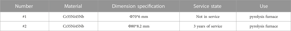
TABLE 1. Raw materials.
In order to get the closest specimenin terms of the actual carburizing damage in the field, for testing, the low-pressure carburizing-vacuum diffusion pulse process is used to carburize the furnace tube. This process is different from the general carburizing process, because it is warmed up under vacuum, thereby effectively reducing the influence of impurities and oxidation process, and excluding the hinderance on the carburizing process resulting from surface oxidation layer.This method can simulate the influence of pure carburizing factors on the organization. At the same time, the carburizing method is conducive to the adsorption process of carbon atoms on the surface of the specimen, and the carburizing rate is fast and efficient.
The vacuum diffusion pulse technique is used to achieve low-pressure carburization of the furnace tube. A double-chamber vacuum carburization furnace is used for the experiments, where the maximum vacuum degree of the heating chamber is 0.4 Pa. The carburization temperature is set to 1,100°C to match the service temperature of the material. The pulse carburization technique involves multiple carburizations and diffusion processes, as shown in Figure 1. At Stage A, acetylene is introduced as a carburizing gas to generate a pressure of 800 Pa. Vacuum is then pumped to Stage B, so that the carbon atoms diffuse into the sample. This process is repeatedly carried out in a pulsating manner, wherein the pulse time is increased until the end of the carburization phase.
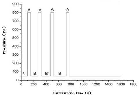
FIGURE 1. Schematic of low-pressure and vacuum carburization technique (A = low-pressure carburization stage, B = vacuum carburization stage, C = vacuum stage, pressure, carburization time).
Carburized layers with different thicknesses can be obtained using the vacuum diffusion pulse technique. The distribution of each element in the carburized area is determined by line scan and surface scan of the electron probe, which is further combined with microhardness and other means to determine the thickness of the carburized layer.
A portable magnetic analyzer is used to investigate the coercivity of each furnace tube at 10 mm, 150 mm, and 290 mm along the longitudinal direction. The furnace tube is circumferentially divided into several regions based on the diameter of the tube, as shown in Figure 2. This is done to test the circumferential and axial coercivity. Since the thickness of the carburizing layer measured by this instrument is the sum of the total thickness of the carburizing layer on the inner and outer walls of the furnace tube, and the carburization often occurs on the inner wall of the furnace tube in actual working circumstances, the outer wall of the furnace tube is turned by 2 mm to remove the carburizing layer on it, and only the carburizing layer on the inner wall is retained. The coercivity test is subsequently conducted again by the same method. The correlation between the thickness of different carburizing layers and the coercivity of the inner wall of the furnace tube is obtained. After collection and analysis of a large volume of experimental data, the relationship between carburized layer thickness and coercivity of the furnace tube is determined.
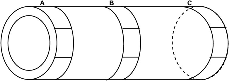
FIGURE 2. Schematic of the coercivity of the test area. (A) 10 mm position of furnace tube. (B) 150 mm position of furnace tube. (C) 290 mm position of furnace tube.
3 Results and analysis
3.1 Coercivity of #1 furnace tube
After being subject to low-pressure and high-temperature carburization at different times, the coercivities of different thicknesses of the strong carburized layer are obtained for furnace tube #1 (Cr35Ni45Nb, Φ 70*6 mm), as listed in Table 2. Due to the formation of different structures on the inner and outer walls during the casting process of the furnace tube, the outer wall is protected by “bayberry” particles. After the experiment, the inner wall has a thicker strong carburized layer as compared to the outer wall. This is to be expected as the furnace tube operates under a high-temperature carburization atmosphere for a long time, and carburization occurs in the inner wall.
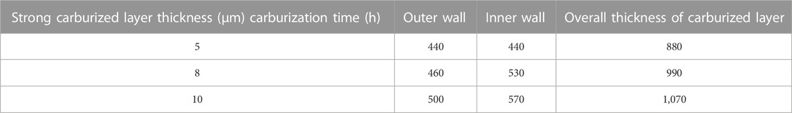
TABLE 2. Results of the thickness of the strong carburized layer in #1 furnace tube after different carburization times.
A portable magnetic analyzer is used to measure the coercivity of furnace tube #1 after being subject to carburization for different durations. The coercivity test is conducted at five uniform areas along the circumferential direction of each furnace tube at 10 mm, 150 mm, and 290 mm, and the coercivity of different areas in each period is plotted in Figure 3 to observe the uniformity of the carburized layer in the furnace tube. It can be observed that the coercivity increases significantly with the overall thickness of the carburized layer in the furnace tube. It has alsobeen found that coercivity in the middle of the furnace tube is larger in comparison to the edge, and the axial coercivity is larger than circumferential coercivity.
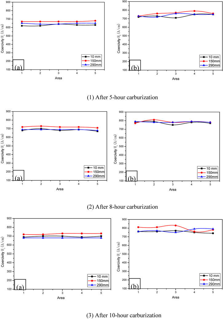
FIGURE 3. (A) Circumferential and (B) axial coercivities in different areas of #1 furnace tube after being subject to different carburization times. (1) After 5-h carburization. (2) After 8-h carburization. (3) After 10-hour carburization.
After the outer wall of the carburized furnace tube is turned by 2 mm, only the carburized layer in the inner wall remains in the furnace tube. The coercivity test is again conducted on the processed tube. As shown in Figure 4, the turning process decreases the overall carburized layer in the furnace tube and causes a significant reduction in the corresponding coercivity. After turning, the coercivity of different axial and circumferential regions of the furnace tube do not show significant fluctuations. This indicates that uniform carburization has occurred on the inner wall, and the carburized layer has a good correspondence with coercivity. Similar to the pristine tube before turning, the coercivity of the center of the turned furnace tube is greater than that of the edge, and the axial coercivity of the furnace tube is greater than the circumferential coercivity.
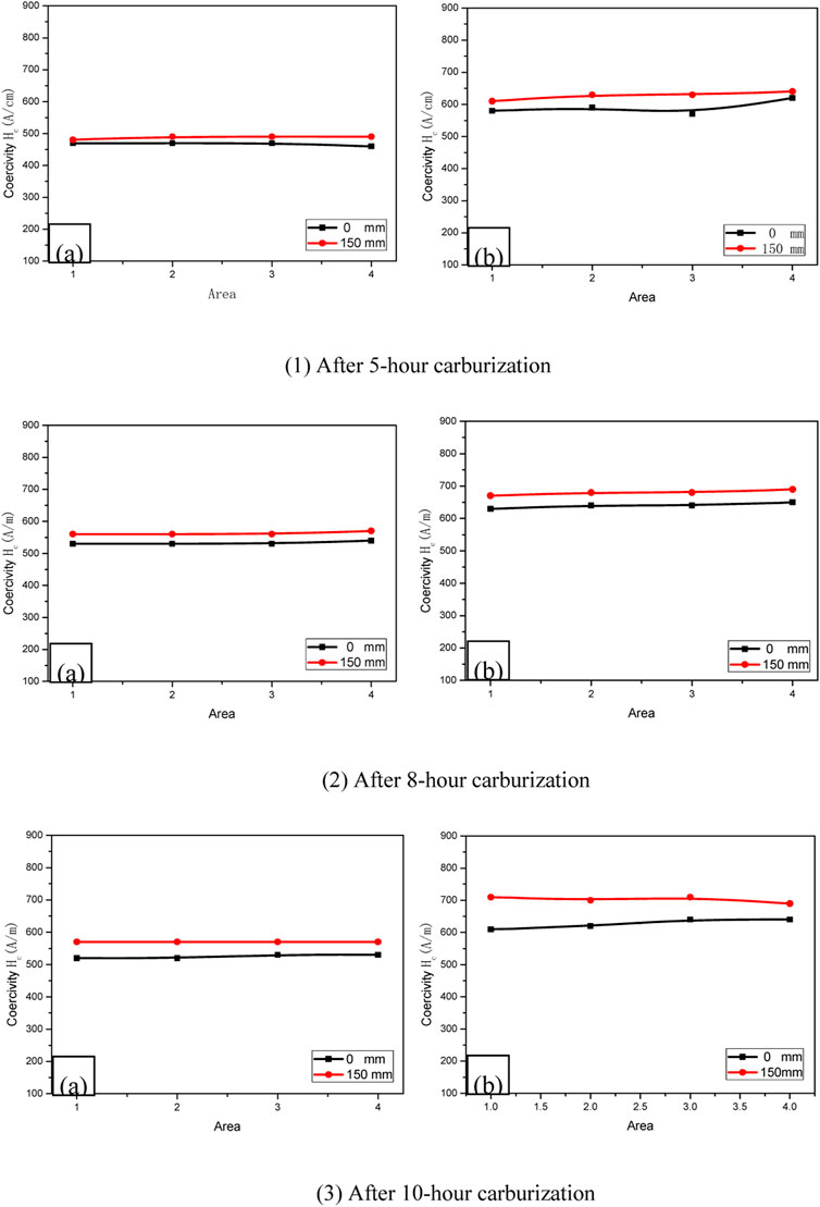
FIGURE 4. (A) Circumferential and (B) axial coercivities in different areas on the outer wall of #1 furnace tube after being turned 2 mm and subject to different carburization times.
The coercivity of the furnace tube, measured by the portable tester, accounts for the overall thickness of the carburized layer in the furnace tube, which takes into account the overall thickness of the inner and outer walls of the carburized layer. Results of the average circumferential and axial coercivity corresponding to the thickness of the strong carburized layer on the inner wall of furnace tube and the overall thickness of the strong carburized layer in the furnace tube prior to turning have been listed in Table 3, and the corresponding relationship has been shown in Figure 5. The coercivity increases with an increase in the thickness of the strong carburized layer in the furnace tube, while the slope exhibits a gradual decline. The experimental data of carburized layer thickness and coercivity presented in Table 3 is subject to polynomial curve fitting and the results have been shown in Figure 5. It can be seen that the fitting curve shows a good agreement with the experimental results. The fitting equation can be obtained as follows:
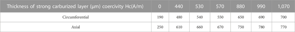
TABLE 3. Thickness of carburized layer in #1 furnace tube corresponding to the coercivity.
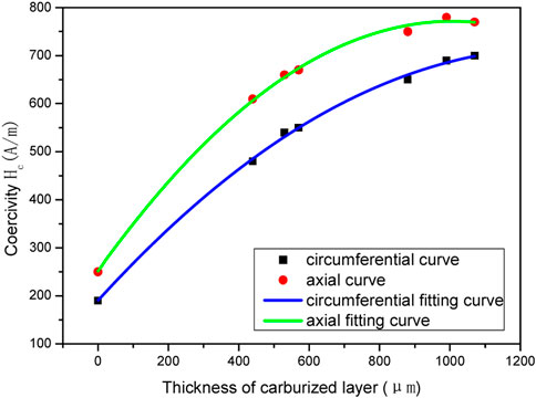
FIGURE 5. Thickness of carburized layer in #1 furnace tube and the relationship between the coercivity (circumferential curve, axial curve, circumferential fitting curve, axial fitting curve).
Circumferential fitting equation:
Axial fitting equation:
Where, y is the coercivity, A/m; x is carburized layer thickness, μm.
Eqs 1, 2 indicate that the experimental data confirms to a quadratic equation of the form,
In the case of furnace tube #2 (Cr35Ni45Nb, Φ80* 8.2 mm), it was observed that 3 years of service caused the inner wall to be severely coked, with the loose coke layer peeling off, resulting in a accumulation of large amount of coke powder in the furnace tube. Before conducting the low-pressure and vacuum experiments, the coke layer of the inner wall of furnace tube is removed, and the inner wall is turned by 0.5 mm to remove the oxidized layer from the inner wall, which is beneficial to the carburization. The carburization of this furnace tube is similar to the process described for furnace #1, wherein low-pressure and vacuum carburization is conducted at 1,100°C for 5 h, 8 h and 10 h to obtain different strong carburized layer thicknesses, as listed in Table 4. The outer wall of the furnace tube has red bayberry particles and is not exposed to the carburization environment during service. Hence it has no carburization layer, whereas the inner wall has a thick carburized layer before being subjected to low-pressure and carburization process. In the experiments involving low-pressure vacuum carburization, both the inner and outer walls are exposed to the carburization environment. As a result, a strong carburized layer also appears upon the outer wall of the furnace tube after the experiment, although the thickness is significantly lower than that of the inner wall. Additionally, thickness of the strong carburized layer on the inner wall increases slightly after carburization.
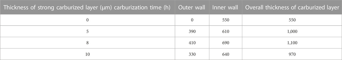
TABLE 4. Results of thickness of strong carburized layer in #2 furnace tube before and after carburization.
The process of testing the coercivity furnace tube #2 with the portable magnetic analyzer is identical to that of furnace #1 described earlier. The relationship of coercivity in different regions has been shown in Figure 6. Since this furnace tube had been in service for nearly 3 years, a carburized layer is present on the inner wall, and the corresponding coercivity is larger than that of the furnace tube #1, which was not in service. Although the thickness of the strong carburized layer on the inner wall does not increase significantly following carburization, there is still an increase in the coercivity. Furthermore, the axial coercivity is higher than the circumferential coercivity owing to the existence of a strong carburized layer on the outer wall.
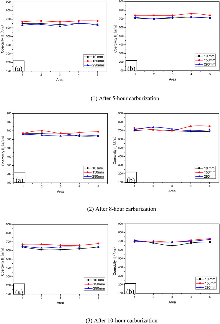
FIGURE 6. (A) Circumferential and (B) axial coercivities in different areas of #2 furnace tube after being subject to different carburization times. (1) After 5-hour carburization. (2) After 8-hour carburization. (3) After 10-hour carburization.
Similar to the process adopted in the study of furnace tube #1, the outer wall of furnace tube is turned by 2 mm after carburization and the coercivity tests are carried out. The relationship of coercivity in each region has been shown in Figure 7, where it can be observed that the coercivity is significantly reduced after turning. Furthermore, the thickness of the carburized layer on the inner wall does not significantly change following carburization, nevertheless, the coercivity still shows significant changes. This result establishes that the device has a high sensitivity to the existence of carburized layer. The absence of any significant fluctuations in coercivity in different regions, regardless of whether it is circumferential or axial, indicates uniform carburization on the inner wall. When the overall carburized layer in the furnace tube undergoes thinning, the coercivity decreases accordingly.
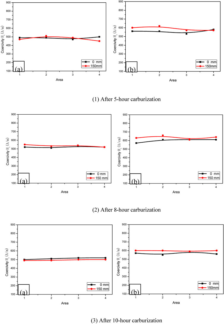
FIGURE 7. (A) Circumferential and (B) axial coercivities of different areas on the outer wall of #2 furnace tube after being turned 2 mm and subject to different carburization times. (1) After 5-hour carburization. (2) After 8-hour carburization. (3) After 10-hour carburization.
The coercivity of the furnace tube measured by portable coercivity tester is aimed at the carburized layer thickness in the overall wall thickness of the furnace tube, which is the sum of inner and outer wall carburized layer thickness. Since furnace tube #2 has been in service for nearly 3 years, there is a 550 μm carburized layer in the inner wall. Because the coke layer is loose, spalling occurs during sample cutting and experimental process. The metallographic structure of samples was investigated by Scanning electron microscopy. The average circumferential and axial coercivity corresponding to the thickness of strong carburized layer on the inner wall of furnace tube and the overall thickness of strong carburized layer in the furnace tube before turning were recorded and have been listed in Table 5, whereas the corresponding relationships have been shown in Figure 8. The coercivity is observed to increase with an increase in the thickness of the strong carburized layer in the furnace tube, whereas the slope shows a gradually decreasing trend. After carburization, the thickness of the strong carburized layer on the inner wall increases slightly, whereas minor changes can be observed in the corresponding coercivity. However, carburization leads to the formation of a carburized layer on the outer wall of the furnace tube, thus increasing the overall thickness of the carburized layer in the furnace tube. As a result, the coercivity increases accordingly, indicating good correlation of coercivity and carburized layer thickness.
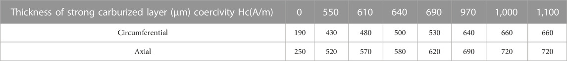
TABLE 5. Thickness of carburized layer in #2 furnace tube and its coercivity.
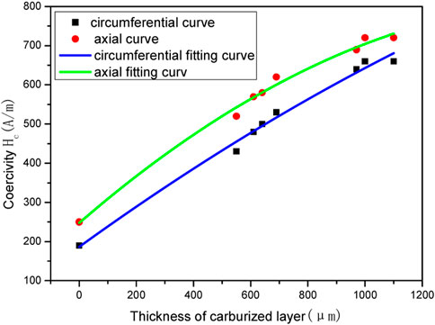
FIGURE 8. Coercivity as a function of thickness of carburized layer in furnace tube #2 (circumferential curve, axial curve, circumferential fitting curve, axial fitting curve).
It is assumed that the coercivity of furnace tube #2 when not in service is the same as that of #1 furnace tube for the carburized layer thickness of 0 mm. Curve fitting is conducted for experimental data corresponding to carburized layer thickness and permeability and the data has been listed in Table 5, whereas the fitting results have been shown in Figure 8. It can be seen that the fitting curve has a good agreement with the experimental results, which proves that the hypothesis is valid. The fitting equation is obtained as follows:
Circumferential fitting equation:
Axial fitting equation:
Where, y refers to the coercivity, A/m; x refers to the thickness of carburized layer, μm.
Similar to the fitting results obtained in the case of furnace tube #1, the experimental data curve confirms to the quadratic equation:
3.2 Comprehensive analysis
Based on the experimental results of different types of furnace tubes and the curve fitting data, it can be concluded that the coercivity essentially depends on the overall thickness of the carburized layer in the furnace tube, and is not affected by the diameter, wall thickness, and axial/circumferential nature of furnace tube. The various carburized layer thicknesses and the corresponding coercivities have been compiled in Table 6. The corresponding experimental data along with the curve fitting has been shown in Figure 9, wherein a fitting accuracy of 97% is achieved, indicating an excellent fit of the experimental results. The fitting equation can be obtained by:
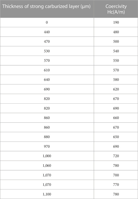
TABLE 6. Thickness of carburized layer vs. coercivity.
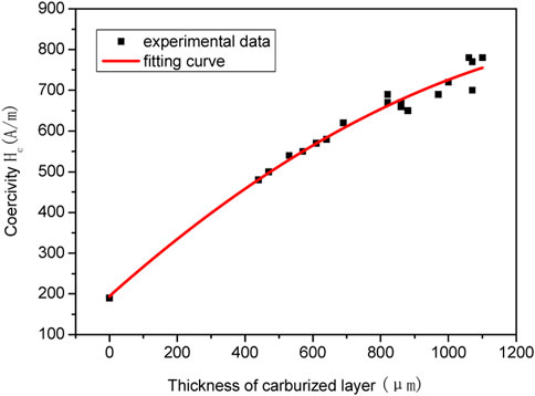
FIGURE 9. Fitting curves of the thickness of carburized layer and coercivity (experimental data, fitting curve).
Where, y refers to the coercivity A/m; x refers to the carburized layer thickness, μm.
Since the maximum thickness of carburized layer in furnace tube is 1 mm in this experiment, based on the experimental data and correlation analysis, it can be ascertained that the coercivity and carburized layer thickness obey Eq. 5 for x < 1 mm, and the corresponding error is less than 100 A/m. As the thickness of the carburized layer is increased, the coercivity shows a flattening trend. This quadratic relationship is generalizable since it is obtained on the basis of experiments performed on pristine and in-service pyrolysis furnace tubes.
4 Discussion
4.1 Organizational changes after carburization
Figure 10 shows the macrostructure of the unserviced Cr35Ni45Nb material, which shows an obvious as-cast tissue shape. The dendrites near the inner wall are coarse and irregularly arranged, and as they move to the outer side, the dendritic tissue becomes increasingly obvious.The orientation is also obvious, with a certain directionality.
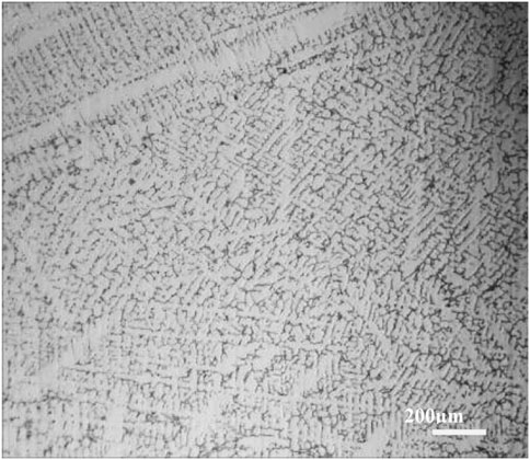
FIGURE 10. Macrostructure of unserviced Cr35Ni45Nb furnace tube.
Unserviced Cr35Ni45Nb material cast state basic organization is composed of almost no precipitation phase of austenite matrix and a skeleton-like and mesh-like eutectic organization, mostly distributed between the dendrites. For the furnace tube material in the centrifugal casting process, the cooling rate is very high, a large amount of carbon is in the form of supersaturated solid solution in austenite, whereas the rest of the carbon is precipitated in the form of interdendritic primary carbides at grain boundaries. At equilibrium cooling of the cast state, precipitation of austenite and M7C3 occurs along with some Nb, Si and other trace elements carbides of the co-crystal as shown in Figure 11A. The tissue morphology of the furnace tube in service for 3 years, following 5, 8 and 10 h of vacuum carburization, has been shown in Figures 11B–D. It can be seen that with the increase of carburization time, the carbide of interdigitated chromium grows significantly and transforms; the skeletal M7C3 carbide transforms to massive striped M23C6; while the white niobium skeletal carbide gradually disappears and transforms to massive, and the diffuse distribution of secondary carbide precipitates asa crystal, which accumulates at the grain boundary.
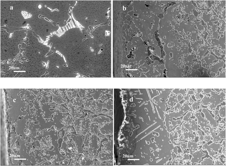
FIGURE 11. Original microstructure of Cr35Ni45Nb furnace tube and the change of organization after carburization [(A) is the original tissue without service, (B) is the tissue shape after 3 years of service and 5 h of vacuum carburization, (C) is the tissue shape after 3 years of service and 8 h of vacuum carburization, (D) is the tissue shape after 3 years of service and 10 h of vacuum carburization].
4.2 Data fitting of coercivity corresponding to carburizing layer thickness
In this experiment, the low-pressure vacuum carburization process was used to investigate the furnace tubes that were not in service and those that had been in service for 3 years. To better simulate the actual furnace tube condition, the tube was first subjected to low-pressure vacuum carburization at different times, and then the outer carburization layer of the tube was turned, whereasonly the inner carburization layer was tested for axial and circumferential coercivity. The test results showed that as the thickness of the carburization layer increased, the corresponding coercivity increased significantly, and there was a good correspondence between the carburization layer and the coercivity.
4.3 Next research direction
First, since the maximum thickness of the carburized layer is only about 1 mm, the fitting equation is only applicable within 1 mm, and in case the carburized layer is larger than 1 mm, it has to be improved in the subsequent experiments to verify the applicability and accuracy of the fitting equation for a carburized thickness of the full tube diameter. Secondly, it was found that the coercivity test was performed after carburization for both the tubes that were not in service and the tubes that were in service for 3 years, and the results showed that the coercivity in the middle of the tubes was larger than that at the two ends.
5 Conclusion
A magnetic analyzer device is introduced for measuring the thickness of carburized layers in pristine and in-service pyrolysis furnace tubes. The furnace tubes are subject to a range of carburization durations to obtain various carburization layer thicknesses. Coercivity measurements are performed for each of the layer thicknesses for both furnaces. Curve fitting results obtained for coercivity as a function of the thickness of carburized layer reveal a quadratic relationship with good fitting accuracy, indicating that coercivity can be employed to characterize carburized layer thickness for pyrolysis furnace tubes. Based on the experimental data pertaining to furnace tube under different conditions, it can be concluded that the coercivity is only determined by the thickness of carburized layer in furnace tube. Furthermore, the coercivity is not directly related to the diameter, wall thickness, and service duration of the furnace tube. A fitting accuracy of 97% and error less than 100 A/m establishes that coercivity is a reliable metric for estimating the thickness of carburization layers in furnaces, irrespective of whether they are pristine or have been in service. Since the maximum thickness of the carburized layer in a furnace tube is 1 mm in this study, the obtained coercivity and the corresponding quadratic equation of carburized layer thickness are fully applicable within a thickness of 1 mm. The method proposed in this study has great industrial potential for monitoring the integrity of pyrolysis furnace tubes and preventing potential failures.
Data availability statement
The original contributions presented in the study are included in the article/supplementary material, further inquiries can be directed to the corresponding author.
Author contributions
CD: writing—original draft preparation; CL: writing and data curation; XL: writing—review and editing; BL: supervision; JL: supervision—review and editing; XT: validation; CS: validation. All authors have agreed to submit the manuscript.
Conflict of interest
The authors declare that the research was conducted in the absence of any commercial or financial relationships that could be construed as a potential conflict of interest.
Publisher’s note
All claims expressed in this article are solely those of the authors and do not necessarily represent those of their affiliated organizations, or those of the publisher, the editors and the reviewers. Any product that may be evaluated in this article, or claim that may be made by its manufacturer, is not guaranteed or endorsed by the publisher.
References
Hasegawa, K., Oikawa, T., and Kasai, N. (2012). Development of an eddy current inspection technique with surface magnetization to evaluate the carburization thickness of ethylene pyrolysis furnace tubes. J. Nondestruct Eval. 31, 349–356. doi:10.1007/s10921-012-0146-8
Heidar Khodamorad, S., and Haghshenas, D. F. (2012). Inspection of carburization and ovalness in ethylene cracking tubes by using a semi-robot. Eng. Fail. Anal. 25, 81–88. doi:10.1016/j.engfailanal.2012.04.006
Jin, P., and Shen, L. (2016). Analysis of failure causes and types of ethylene pyrolysis furnace tubes. Chem. Eng. Mach. 43 (3), 263∼267.
Kasai, N., Owaga, S., Oikawa, T., Sekine, K., and Hasegawa, K. (2010). Detection of carburization in ethylene pyrolysis furnace tubes by a C core probe with Magnetization. J. Nondestruct Eval. 29, 175–180. doi:10.1007/s10921-010-0075-3
Li, H., Wu, B., Tang, R., Wang, Y., Liu, X., and He, C. (2022). Nondestructive evaluation of carburized layer depth in furnace tubes of Cr35Ni45NbMA using magnetic field distortion and magnetic attraction force measurement methods. Measurement 191 (191), 110845. doi:10.1016/j.measurement.2022.110845
Lian, X., Chen, X., and Li, Y. (2016). Study on detection of pyrolysis furnace tubes carburization based on magnetic flux intensity. Press. Vessel Technol. 33 (5), 56∼61.
oshioka, S. Y., Marumoto, T., and Gotoh, Y. (2019). Electromagnetic inspection method of carburization depth inside and outside of heating furnace steel tube. Int. J. Appl. Electromagn. Mech. 59 (59), 1283–1290. doi:10.3233/jae-171112
Stevens, K. J., and Trompette, W. J. (2004). Calibration of eddy current carburization measurements in ethylene production tubes using ion beam analysis. J. Phys. D. Appl. Phys. 37, 501–509. doi:10.1088/0022-3727/37/3/031
Takahashi, S., Sato, Y., Kamada, Y., and Abe, T. (2004). Study of chromium depletion by magnetic method in Ni-based alloys. J. Magnetism Magnetic Mater. 269 (2), 139–149. doi:10.1016/s0304-8853(03)00584-5
Wu, J. (2013). Cause analysis and countermeasure of the failure of the radiant tube in ethylene pyrolysis furnace. Petro Chem. Equip. 16 (8), 30∼33.
You, Z. (2007). Failure analysis of the tubes of ethylene pyrolysis furnaces. Chem. Eng. Mach. 34 (6), 346∼348.
Zhang, S. (2016). Detection of microstructural daamages and defects using electromagnetic testing and ultrasonic guided waves [D]. Shanghai, China: East China University of Science and Technology.
Keywords: pyrolysis furnace tube, magnetic analyzer, coercivity, detection of carburization layer, fitting equation
Citation: Du C, Liu C, Li X, Liu B, Lu J, Tan X and Song C (2023) Application of magnetic analyzers for detecting carburization of pyrolysis furnace tubes. Front. Mater. 10:1147125. doi: 10.3389/fmats.2023.1147125
Received: 18 January 2023; Accepted: 03 March 2023;
Published: 15 March 2023.
Edited by:
Ahmed Abdel Nazeer, National Research Centre, EgyptReviewed by:
Vaibhav Kathavate, North Carolina State University, United StatesKhaled M. Chahrour, Karabük University, Türkiye
Copyright © 2023 Du, Liu, Li, Liu, Lu, Tan and Song. This is an open-access article distributed under the terms of the Creative Commons Attribution License (CC BY). The use, distribution or reproduction in other forums is permitted, provided the original author(s) and the copyright owner(s) are credited and that the original publication in this journal is cited, in accordance with accepted academic practice. No use, distribution or reproduction is permitted which does not comply with these terms.
*Correspondence: Xiaowei Li, bGl4aWFvd2VpY2dAMTYzLmNvbQ==