 Joyce Kamau
 Joseph Podolsky
 R. Christopher Williams
- 1Graduate Research Assistant, Department of Civil Construction and Environmental Engineering, Iowa State University, Ames, IA, Unites States
- 2MnROAD Research Implementation Engineer, Minnesota Department of Transportation Office of Material and Road Research, Maplewood, MN, Unites States
- 3Department of Civil Construction and Environmental Engineering, Iowa State University, Ames, IA, Unites States
Longitudinal joint cracking in Hot Mix Asphalt (HMA) pavements is a major issue that occurs because high density (low air voids) is not easily achieved during construction as compared to the mat away from the joints. High air voids allow water infiltration, which results in moisture-induced damage to the pavement and reduced pavement service life. The use of a Void Reducing Asphalt Membrane (VRAM) has been recommended and used at longitudinal joints of asphalt pavements as a preventative treatment to achieve good performance and increase density/reduce air void content at the longitudinal joint. The Void Reducing Asphalt Membrane material is sprayed on top of a tack coat at the longitudinal joint, 9 inches on each side of the joint below the Hot Mix Asphalt surface overlay, and is expected to migrate upward into the Hot Mix Asphalt overlay, filling 50%–70% of the air voids. This study evaluated and compared the performance of longitudinal joints constructed with Void Reducing Asphalt Membrane to that of a joint without Void Reducing Asphalt Membrane (control). Field cores were collected from 1) a section containing Void Reducing Asphalt Membrane and 2) a section without Void Reducing Asphalt Membrane that was paved for this research. Falling head permeability was carried out to determine the permeability coefficient of the specimen. Disk Compact Tension (DCT) and Semi-Circular Bend (SCB) tests were used to evaluate the cracking performance at low temperatures. A push-pull test was used to evaluate the improvement in adhesion between the top and bottom Hot Mix Asphalt layers at the intermediate temperature. The VRAM-containing samples show high values of fracture energy (Gf) and surface and joint bond energies as compared to the control sections. High surface and joint bond energies indicate that longitudinal cracking at the joints will be delayed as more energy is required to initiate cracks. Additionally, the VRAM-containing samples have a lower permeability coefficient compared to the control section. This indicates that the Void Reducing Asphalt Membrane reduces the possibility of water infiltration. The elastomeric polymer in the Void Reducing Asphalt Membrane increases the cohesion in the mixture, which increases the resistance to deformation and improves the bond strength of the joint Additionally, the Void Reducing Asphalt Membrane enhances the elasticity of the binder, thus increasing the cracking resistance of the joint.
Introduction
The quality of longitudinal joints is critical for the long-term performance of Hot-Mix Asphalt (HMA) pavements. On the other hand, during construction, the longitudinal joint often does not achieve the target compaction compared to the mat, leading to a high air void content or low-density joint. The high air voids will increase the possibility of void interconnection, resulting in a more permeable asphalt mixture. Permeability exposes the pavement to water and air infiltration, which in turn can cause premature pavement failure (Williams et al., 2009). Water causes moisture-related damage, while oxygen accelerates binder hardening through oxidation, resulting in a more brittle asphalt mix. Brittle asphalt mixes are more susceptible to cracking.
The need to keep the road accessible to traffic during construction, the availability of construction equipment, and operational efficiency lead to the paving of lanes in a single pass (e.g., 12 ft wide). During the second pass of paving, there is a hot and cold asphalt mixture at the joint, as shown in Figure 1. The longitudinal butt joint is mostly used in HMA pavement construction. The hot and cold mixtures always compromise the bonding of the mixture at the joint, often resulting in high air voids. Additionally, the lane constructed first has an unconfined joint that will flow laterally during compaction and thus usually has higher air voids at the edge (Circular and Transportation Research BoardNational Academies of SciencesEngineeringMedicine, 2006; Williams, 2011; Buncher, 2012).
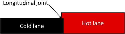
FIGURE 1. Construction technique for longitudinal butt joints.
Different longitudinal joint construction techniques have been used in the United States to achieve longitudinal densities that provide long-term performance equivalent to the center of the roadway mat. These construction techniques are echelon/tandem paving, joint types (butt, tapered, and notched wedge), edge restraining, infrared joint heaters, joint adhesives, cutting wheels, various rolling patterns, hot overlap, and joint sealants (Williams, 2011), (Buncher, 2012). In addition to construction techniques, both physical properties and aggregate gradation play an important role in achieving the required air voids for better performance.
Aggregate gradation is one of the characteristics that is relied upon by the asphalt mixture to carry loads. Variability in aggregate gradation in an HMA mix can result from quarry production, mixing, placement, and compaction. To control the variability, the range of aggregates to be used for a design is determined during design. Numerical simulations are also used to limit the variability of the aggregate gradation (Fang et al., 2019). Fine and coarse aggregates compact differently and thus affect the number of air voids and how they interconnect in the pavement, as they have different particle packing in the structure. Different materials have also been used as joint adhesives and sealants (Mcdonald, 2018), (Montgomery and Haddock, 2018). The primary intent is to prevent the infiltration of air and water into the pavement, thereby preserving the integrity of the joint (Williams, 2011).
Void Reducing Asphalt Membrane, VRAM, also known as Longitudinal Joint Sealant (LJS), is a composite material that comprises an asphalt binder, an elastomeric polymer, and a wax modifier. It may further consist of either fumed silica or fumed alumina, or a saponified fatty acid and a resin acid gelling compound. VRAM is applied either below the HMA layer at the longitudinal joint or on the vertical face of the first pass (Kriech et al., 2016). A spray truck is used to apply the asphalt membrane as a heavy fluid membrane. The VRAM is believed to migrate upward into the HMA overlay during placement and compaction, filling 50%–70% of the air voids (Figure 2) and thus reducing the interconnectivity of the air voids, hence reducing permeability and increasing the density of the pavement system (Heritage research group, 2018), (Transportation and Conference, 2016). This can be used to mitigate the typically higher air void structure that is usually located within ± nine inches of the longitudinal joint and to make the pavement system more structurally sound. During the construction of the joint sealant evaluation for the Indiana DOT, VRAM migration was observed to be approximately 13 mm. This is less than 50% migration for a surface mixture that is 32 mm, which is slightly less than the minimum value of the desired 50%–75% migration (Montgomery and Haddock, 2018).
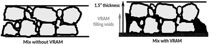
FIGURE 2. Illustration of the migration of VRAM into the asphalt mixture (Thomas and Zahrn, 2022).
The VRAM is placed on the existing surface of the pavement in sufficient amounts to allow migration into the new overlay. The wax modifier at elevated temperatures reduces the viscosity of the composition, allowing it to migrate. The composition is also modified to ensure that it does not flow before the placement of the HMA. Once applied, the composition quickly loses its tackiness, allowing construction traffic to drive over within 15–30 min of placement. The composition migrates to fill some of the air voids in the HMA overlay placed over it. VRAM can be applied under the HMA or on the vertical face of a constructed asphalt pavement mat (Kriech et al., 2016).
A study in the State of Illinois concluded that LJS extended the performance of the joint area by approximately 3–5 years, with a realized benefit of three to five times the initial cost of using the LJS. Additionally, increased crack resistance and decreased permeability were observed in the laboratory testing of the cores of the mix near the joint with LJS (Trepanier et al., 2021). Indiana, Minnesota, and Illinois are some of the states that have implemented the use of VRAM as a material approach to preserve the longitudinal joint (Transportation and Conference, 2016; Thomas and Zahrn, 2022).
Implementing a longitudinal joint specification has been recommended as a method to improve pavement performance. According to researchers from Purdue, in 2011, only 12 state departments of transportation (DOTs) in the United States had specifications that included a longitudinal joint density requirement. The specification should allow contractors some flexibility. However, implementing these specifications requires some means of testing the quality of the joint. Density near the joint has been used as a measure of pavement performance (McDaniel et al., 2012). Other performance tests, such as joint crack resistance and bonding, have not been explored, especially in regions experiencing low-temperature climates.
Materials and methods
Materials
Field cores were obtained from TH22 in Mankato, Minnesota, between Knewtson Soy Products LLP and 1 mile north of Decoria Cemetery. The pavement had a 1 ½” to 2″ HMA overlay containing a PG58H-34 binder over an existing asphalt surface. Cores were obtained from two one-mile sections of the pavement: A control section and a VRAM-containing section, both constructed in 2018. Prior to paving the VRAM-containing section, an 18” width of VRAM was applied where the overlay centerline construction joint would be placed using a spray truck. Both sections were constructed using the traditional joint construction method, commonly referred to as a butt joint. VRAM is a composite material that comprises an asphalt binder, an elastomeric polymer, and a wax modifier.
For each test, six field cores were collected from each section of the pavement: three from the longitudinal joint and three from the mat away from the VRAM application area. For the VRAM sections, cores were taken at the longitudinal joints, while for the control section, they were obtained next to the longitudinal joint (as per the MnDOT specifications). All cores were 150 mm in diameter, except for those used for surface bond energy testing, which were 100 mm in diameter. VRAM-containing cores were frozen, and then the smeared VRAM was scraped from the outside of the cores before any further sample preparation.
Methods
Falling head permeability test
Laboratory tests were conducted on field-obtained core specimens to measure the permeability of asphalt mixtures. The Florida DOT falling head permeability test method was used. Cores were obtained by cutting just below the interface. A falling head permeability test was carried out on the full samples, which included the core with both the existing layer and the overlay. Subsequently, each specimen was sawed in half, as shown in Figure 3. A falling head permeability test was again conducted on each sample’s top and bottom halves.
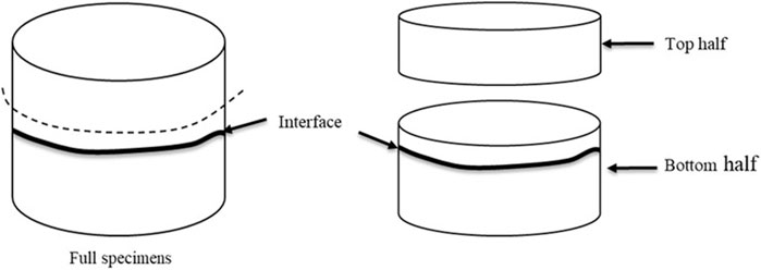
FIGURE 3. Falling head permeability samples.
Cracking resistance test
A low-temperature directional bend test, similar to the single-edge notch test, was performed to measure cracking at low temperatures (Wagoner et al., 2005) Click or tap here to enter text. The specimen had similar geometry to the specimen used in AASHTO TP 105–13. Cores were cut 40 mm below the interface and then cut into a rectangular shape, as shown in Figure 4. Consequently, a notch was cut within 5 mm of the interface. The prepared samples were then conditioned at the test temperature for a minimum of 2 h before testing. The test was performed at run travel speed and temperature using current Minnesota DOT practices.
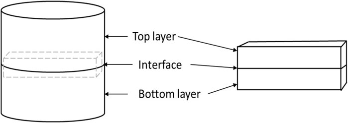
FIGURE 4. SCB specimen preparation.
Bond energy tests
Two test methods were used to measure interface bond energy: The first to measure bond energy at the surface, and the second to measure bond energy at the joint. The joint bond energy was used to evaluate the bond between the two adjacent lanes that were paved at different times, hence having a cold mixture from the lane paved first and a hot mix while the second lane was being paved. Surface bond energy is the bond between the existing surface and the overlay. The method used to measure bond energy at the surface is similar to the viscoelastic continuum damage (VECD) approach, except that the test specimen was tested in direct tension mode at a constant rate of 0.5 mm/min instead of testing in push-pull mode with a uniaxially-sized specimen (100 mm diameter by 150 mm height). Cores were cut 5 mm below the interface to perform the surface bond energy tests. AMPT/UTM was performed in direct tension mode, 4°C, 0.5 mm/min, as shown in Figure 5.
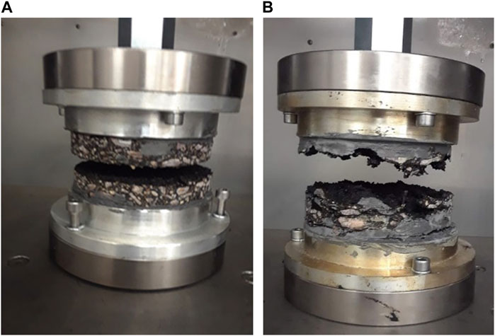
FIGURE 5. Bond surface energy testing in AMPT; (A) control sample with a normal bonding material (B) sample with VRAM layer.
The method used to evaluate the bond energy at the joint is the Disk-shaped Compact Tension (DCT) test, a test used to characterize low-temperature cracking of asphalt mixtures. Cores were cut ∼ 5 mm below the interface, and samples were prepared similarly to the DCT test configuration. The samples were then conditioned at the test temperature for a minimum of 2 h before testing. The DC(T) test apparatus was used to perform the test, which was conducted at −12°C and a crack opening rate of 1 mm/min. The work of fracture is calculated as the area under the load versus the load line displacement curve. This is plotted from the load and crack opening data. The work of fracture is then divided by the crack area to calculate the energy required, which includes both the bond energy and the fracture energy.
Results and discussion
Table 1 shows the coefficient of permeability values obtained by running the falling head permeability test for the entire specimen (overlay and existing layer core) and both the top and bottom halves, as per Figure 3. The falling head permeability coefficient result shows that the VRAM reduced the permeability coefficient of the pavement. For the full specimen, the VRAM-containing specimen at the joint had a zero permeability coefficient on average. A 9 mm drop in the head of water was observed for the VRAM-containing sample for the first 10 min. It was insignificant after calculation, but it showed that the top layer still had sufficient air void content; however, these may not be connected. The height of the water remained stagnant for the rest of the test time. There was no water flowing through the specimen, as no water was observed flowing through the outlet. This shows that the VRAM layer either sealed the air voids or the sample acted as a waterproofing agent. The result shows that the bottom half of the specimen for the VRAM-containing specimen at the joint has a coefficient of permeability value of zero because it is the half that had the VRAM layer. The top half of the same sample had a coefficient of permeability value of 1.5*10−5 cm/s, which is much lower compared to the other specimen, indicating that the VRAM had migrated into the overlay and reduced the number of interconnected air voids, thus reducing the permeability of the joint.
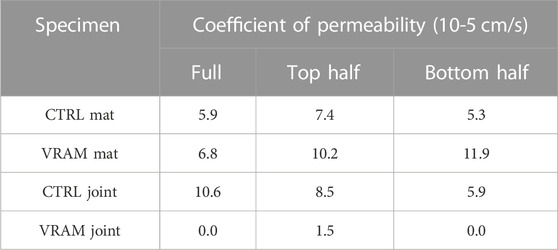
TABLE 1. Average permeability results from the whole, top, and bottom halves of specimens.
Figure 6 and Figure 7 also show that the bond energy decreased as the temperature dropped from −12 to −24°C, and the error bars are shown on the bar graphs This can be attributed to the asphalt mixture becoming more brittle as the temperature decreased and the binder component of the mixture also becoming more fragile and thus more prone to cracking. The VRAM-containing section was more affected, as the joint bond energy decreased by a factor of 2.04 as compared to a factor of 1.46 for the control.
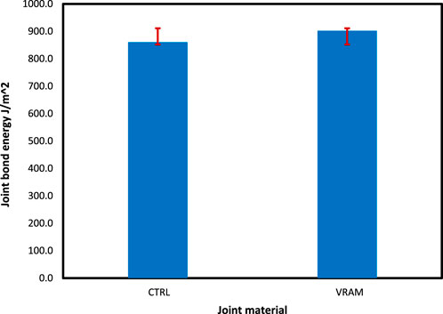
FIGURE 6. Bond energy at the joint results at -24°C.
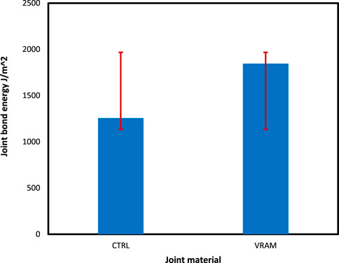
FIGURE 7. Bond energy at the joint results at −12°C.
At −24°C, the VRAM sample exhibited a joint bond energy of 902.5 J/m2 compared to the control with a mean of 860.6 J/m2. With an increase in temperature to −12°C, the mean for the VRAM sample was 1845.4 J/m2 compared to 1256 J/m2 for the control. The difference between the VRAM and control samples means was 589.4 and 41.9 J/m2 for −12 to −24°C, respectively. VRAM has a polymer that increases the cohesion in the mixture, which in turn increases the resistance to deformation.
The fracture energy is shown in Figure 8, with the error bar plotted on the bar graph The fracture energy was used as an indicator of the fracture/cracking resistance of the samples. The average Gf is 782.3 J/m2 for the VRAM-containing specimen compared to the control section, which had an average fracture energy of 579 J/m2. This is a difference of 203.3 J/m2. All of the VRAM-containing samples had high values of fracture energy, above the mean value for all the samples. For our samples, the VRAM-containing specimen showed increased mixture cracking resistance as compared to the control section. The VRAM enhances the elasticity of the binder, thus increasing the cracking resistance at the joint.
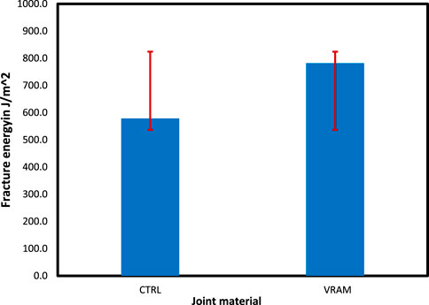
FIGURE 8. Fracture energy results at -12°C.
A high surface bond was observed for the VRAM-containing section compared to the control samples, as shown in Figure 9. The test was performed on a 100 mm diameter sample in tension loading mode at 4°C. The VRAM samples exhibited high values of surface bond energy compared to the control samples. The elastomeric polymer in the VRAM enhanced the bond strength of the joint.

FIGURE 9. Bond energy at the surface.
Figure 10 shows images of the surface bond energy test sample after the test was completed. The control sample cracked at the joint interface between the overlay and the existing layer; this could be considered a clean cut, while the VRAM-containing sample cracked not through the interface but above or below the interface in a zigzag pattern.
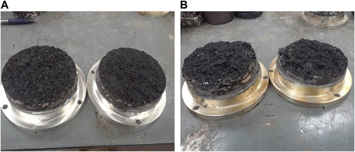
FIGURE 10. (A) Control and (B) VRAM-containing specimen.
The VRAM-containing samples exhibited mean values for fracture energy, joint bond energy, and surface bond energy that were all higher than the control samples. Additionally, the VRAM-containing samples had a standard deviation, as shown in Table 2, for joint bond and fracture energy. This can be attributed to the uneven distribution of the VRAM due to non-uniform migration since VRAM migration depends on the temperature of the placed overlay mixture and compaction. Different locations of the mixture may have lower temperatures, especially the side of the sample that was in the cold mixture during construction, as the VRAM samples contain both the hot and the cold parts of the mix. Some specimens will therefore have higher fracture energies than others.
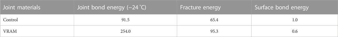
TABLE 2. Standard deviations.
Statistics
Table 3 shows the p-values for the t-test, assuming unequal variance between the samples for the VRAM and the control. The test was to determine if VRAM improved performance. The alternative hypothesis was VRAM-control >0. The joint bond energy mean values were observed to be not statistically significantly different between the VRAM-containing and control samples. The fracture energy and surface bond energy mean values were statistically significantly higher for the VRAM-containing samples compared to the control with 95% confidence. Thus, it can be concluded that the use of VRAM improves the fracture resistance at the longitudinal joint, as shown by the high fracture energy. Additionally, the bond between the existing surface and the HMA overlay is improved by the use of VRAM.
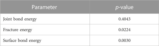
TABLE 3. T-score with 95% confidence level (α = 0.05).
Summary and conclusion
This study shows that the use of VRAM is a performance-enhancing strategy. The specimens containing VRAM have the highest values of surface and joint bond energy and fracture energy as compared to the control sections. High surface and joint bond energies indicate that longitudinal cracking at the joints will be delayed since it takes more energy to cause a unit crack. The cracking resistance at the joint will be improved, as shown by the high fracture resistance values.
The low coefficient of permeability value obtained for the top half of the VRAM-containing joint is an indicator of the improved permeability performance of the pavement joint. A 9 mm drop in the head of water observed during the permeability test shows that the pavement surface layer still has sufficient air void content.
In the future, it is recommended that more sections be examined to study how pavement performance is improved and affected by variables such as construction methods, binder grades used, and overlay thickness. Performance tests at intermediate and high temperatures could also be evaluated in the future.
The success of a pavement treatment or design methodology is to apply the right treatment to the right pavement at the right time to prolong the life of the pavement, thus saving or delaying future expenditures with the aim of good long-term pavement performance. The use of VRAM in the pavement joint during construction has been shown to improve crack resistance and reduce permeability. The high fracture energy is indicative of crack resistance, and the difference in means between the VRAM and control samples was shown to be statistically significant with 95% confidence. The elastomeric polymer in the VRAM increases the cohesion in the mixture, increasing resistance to deformation and improving the bond strength of the joint. Additionally, the VRAM enhances the elasticity of the binder, thus increasing the cracking resistance at the joint. (Illinois, 2022; Indiana, 2022).
Data availability statement
The original contributions presented in the study are included in the article/Supplementary Material, further inquiries can be directed to the corresponding author.
Author contributions
The authors confirm their contribution to the paper as follows: analysis and interpretation of results, data collection, and draft manuscript preparation JK. JP study conception and design. RW study conception and design. All authors contributed to the article and approved the submitted version.
Funding
The Minnesota Department of Transportation financially supported this research (MnDOT NS-512).
Conflict of interest
The authors declare that the research was conducted in the absence of any commercial or financial relationships that could be construed as a potential conflict of interest.
Publisher’s note
All claims expressed in this article are solely those of the authors and do not necessarily represent those of their affiliated organizations, or those of the publisher, the editors and the reviewers. Any product that may be evaluated in this article, or claim that may be made by its manufacturer, is not guaranteed or endorsed by the publisher.
References
Buncher, M. (2012). Best practices for constructing and specifying HMA longitudinal joints A Co-operative effort between the asphalt institute and the federal highway administration final report. Lexington, Kentucky: Asphalt Institute.
Circular and Transportation Research BoardNational Academies of Sciences Engineering Medicine Ray Brown, E. (2006). Factors affecting compaction of asphalt pavements. Transp. Res. Board. National center for asphalt technology, E-C105. doi:10.17226/23282
Fang, M., Park, D., Singuranayo, J. L., Chen, H., and Li, Y. (2019). Aggregate gradation theory, design and its impact on asphalt pavement performance: A review. Int. J. Pavement Eng. 20 (12), 1408–1424. doi:10.1080/10298436.2018.1430365
Heritage research group Exline, Marvin (2018). Void reducing asphalt membrane (VRAM) - improving longitudinal joint performance. Cty. Eng. workshop Bellaire Mich. Affliation Asphalt Material inc/Heritage group.
Illinois, D. O. T. (2022). Standard specifications for road and bridge construction standard specifications for road and bridge construction. Washington, United States: United States Department of Transportation.
Indiana, D. O. T. (2022). Standard specifications for road and bridge construction standard specifications for road and bridge construction. Washington, United States: United States Department of Transportation.
Kriech, A. j., Wissel, H. L., Reece, T. P., and Keller, M. (2016). “(12) patent application publication (10),”. Pub No: US 2016/0271610 A1 Patent Application Publication, 1–5.1, 19.
McDaniel, R. S., Shah, A., and Olek, J. (2012). Longitudinal joint specifications and performance. West Lafayette, United States: Purdue university, 53.
Montgomery, S. R., and Haddock, J. E. (2018). Joint sealant performance on asphalt mixture longitudinal joints. Mix Asph. doi:10.12783/aapt2018/33804
Thomas, T., and Zahrn, T. C. (2022). Void reducing asphalt membrane benefits at centerline joints. Asph. Mater.
Transportation, O., and Conference, E. (2016). “Void reducing asphalt membrane for extending longitudinal joint life of asphalt pavements,” in Ohio Transportation Engineering Conference, Columbus, Ohio, October 2016.
Trepanier, J., Senger, J., Thomas, T., and Exline, M. (2021). A materials approach to improving asphalt pavement longitudinal joint performance. J. Transp. Res. Board, 1–15. doi:10.1177/03611981211044451
Wagoner, M. P., Buttlar, W. G., and Paulino, G. H. (2005). Disk-shaped compact tension test for asphalt concrete fracture. Exp. Mech. 45 (3), 270–277. doi:10.1177/0014485105053205
Williams, S. G., Pervis, A., Bhupathiraju, L. S., and Porter, A. (2009). Methods for evaluating longitudinal joint quality in asphalt pavements. Transp. Res. Rec. 2098, 113–123. doi:10.3141/2098-12
Keywords: performance, permeability, fracture energy, bond energy, fracture resistance, longitudinal joint, void reducing asphalt membrane
Citation: Kamau J, Podolsky J and Williams RC (2023) Performance evaluation of a HMA pavement longitudinal joint containing a void reducing asphalt membrane (VRAM). Front. Mater. 10:1154873. doi: 10.3389/fmats.2023.1154873
Received: 31 January 2023; Accepted: 29 May 2023;
Published: 06 July 2023.
Edited by:
Zhanping You, Michigan Technological University, United StatesReviewed by:
Huanan Yu, Changsha University of Science and Technology, ChinaHui Yao, Beijing University of Technology, China
Copyright © 2023 Kamau, Podolsky and Williams. This is an open-access article distributed under the terms of the Creative Commons Attribution License (CC BY). The use, distribution or reproduction in other forums is permitted, provided the original author(s) and the copyright owner(s) are credited and that the original publication in this journal is cited, in accordance with accepted academic practice. No use, distribution or reproduction is permitted which does not comply with these terms.
*Correspondence: Joyce Kamau, andrYW1hdUBpYXN0YXRlLmVkdQ==