 Gyu-Wol Lee1
 Jong-Hwan Yun
 Min-Soo Kang
- 1Division of Smart Automotive Engineering, Sun Moon University, Asan-si, Republic of Korea
- 2Regional Innovation Platform Project of Kongju National University, Cheonan-si, Republic of Korea
- 3JinSung Boltech Corporation, Asan-si, Republic of Korea
This study evaluates the mechanical strength of 3D-printed objects of composite material. The composite material considered in this study comprises onyx as the base material with glass fiber and carbon fiber as the internal reinforcements. 3D printing using composite materials generally involves laminating fiber reinforcements in the form of layers within the printed part. To analyze the effect of such reinforcements on the printed parts, specimens were prepared by varying the number of layers and arrangement conditions of the reinforcement. The analysis shows that the tensile strength of the composite increases with the number of reinforcement layers due to the effect of the fibers on the longitudinal direction and a larger bonding area between the internal Onyx and the fibers. Furthermore, higher tensile strength is observed when the reinforcements are laminated at regular intervals than when they are arranged in the center. This study serves as a database for 3D printing fiber-reinforced composites aiding future research in comparing and optimizing their strength according to the 3D printing conditions.
1 Introduction
Three-dimensional (3D) printing is an additive manufacturing method that receives 3D modeling data, melts various materials, and stacks them to create a 3D structure, in contrast to the cutting process used in conventional manufacturing (Cheng et al., 2020; Yan et al., 2021; Sun and Wu, 2022). In 3D printing, innovative techniques are used to customize shapes and textures by fabricating objects into precise 3D shapes. It generally proceeds quickly from the design stage to prototype production and testing and is extremely economical (Le Tohic et al., 2018; Eisenberg et al., 2013). Additive manufacturing in 3D printing includes several methods, including selective laser sintering (SLS) (Fina et al., 2017; Shirazi et al., 2015; Awad et al., 2020), stereolithography (SLA) (Martín-Montal et al., 2021; Wang et al., 2016; Manapat et al., 2017), polyjet (Tee et al., 2020; Kabandana et al., 2022), and fused deposition modeling (FDM) (Kollamaram et al., 2018; Montero et al., 2001; Rahim et al., 2019). In the SLS method, powder-type materials are temporarily melted with a laser and then fused together into the desired shape. In the SLA method, the laser beams of a specific wavelength are reflected off a mirror to harden the liquid resin. In the polyjet method, a photocurable liquid resin is sprayed through a nozzle, which is solidified c using a UV light source. Thus, 3D printing includes various types of additive manufacturing methods, each with its own characteristics as well as advantages and disadvantages. FDM is the most widely used additive method. In this method, a filament-type thermoplastic material is melted in a nozzle and stacked up from the bottom while the melted material is solidified in the required part. The size and detail of the layer are determined by the speed and force with which the material is melted and extruded through the nozzle.
Recently, have investigated the use of FDM for printing composite materials. In addition, composite material 3D printing has garnered worldwide attention owing to the promising research in this field. Various studies have scrutinized the different types and structures of composite materials and conducted comparative analyses of tensile strength according to filling patterns, isotropic fiber (Mei et al., 2019; Kriz and Stinchcomb, 1979) and concentric fiber method (Araya-Calvo et al., 2018; Morales U et al., 2021). Research has also been extended to comparing the thermal conductivity and elasticity of composite materials with applications in a wide range of industries and experiments. Typically, even a small amount of reinforcement (fiber) added to the main material (filament) results in composite parts with enhanced mechanical properties and specific strength superior to that of steel. Current 3D composite printing uses onyx with reinforcement layers. Onyx has been measured to be 1.4 times stronger and stiffer than ABS, has a flexural strength of 81 MPa and a flexural stiffness of 2.9 Gpa. Additionally, it has high tensile strength and heat resistance, is easy to print, and is robust in assembly (Bárnik et al., 2019). Furthermore, it combines well with continuous filament fabrication (CFF)-based (Galati et al., 2021; Parmiggiani et al., 2021) fiber materials such as carbon fiber (CF) (Newcomb, 2016) and glass fiber (GF) (El-Tayeb and Gadelrab, 1996). However, owing to its vulnerability to moisture absorption the filament requires careful management (Moreno-Núñez et al., 2023). Onyx is used in most composite material 3D printers as it has good bonding strength with various fiber reinforcements, such as CF, GF, and Kevlar (Morales M A et al., 2021; Tian et al., 2021). Among them, CF is extremely light and does not deform easily, its strength is comparable to aluminum, which is a popular 3D printing material, and possesses excellent heat resistance and impact resistance. In addition, its mechanical properties are superior to those of GF composite materials and it is an ultra-lightweight alternative to next-generation metals. CF is 6 times stronger and approximately 18 times harder than onyx fibers. GF is most often used in fiber-reinforced plastics, has excellent heat-insulating properties, does not rust, and is easy to process. GF composite materials are less expensive than other composite materials, have excellent durability, have no electrical conductivity, and have excellent resistance to impact damage. GF is 2.5 times stronger and 7 times harder than onyx. Therefore, it is used as a general-purpose material that complements the mechanical properties of onyx-based composite materials. However, CF and GF are approximately 13 and 8 times more expensive than onyx, respectively.
Therefore, to print efficiently, the printing process must be optimized while maintaining the mechanical strength of the printed parts. Such optimization requires a database on the effects of various thicknesses and arrangement positions of CF and GF layers inside onyx on the properties of the printed part. Therefore, in this study, the mechanical strength characteristics of composite printed parts were analyzed according to the type and arrangement of reinforcements. Onyx was selected as the base material, CF and GF were selected as reinforcements, and the mechanical behavior was studied according to the change in thickness and position of the CF and GF layers.
2 Materials and methods
2.1 Test specimen
The tensile test standard used in this study was performed by citing the international test standard ISO 527-4, which defines test conditions for isotropic and orthotropic fiber-reinforced plastic composites. ISO 527-4 presents a standardized size for tensile testing of specimens (Pisanu et al., 2021). According to the above standard, the size of the test specimen was set as shown in Figure 1A. 3D modeling was performed to obtain a test specimen 150 mm long, 10 mm wide, and 2.5 mm thick, and the gauge length was set to 50 mm. The conditions that were set for composite material 3D printing are as follows. The composite material for 3D printing was set to 30% of the internal filling density in a grid-type pattern to proceed with the evaluation under conditions similar to the grid pattern of 30% of the PLA material. The onyx thickness of the upper shell and lower surface of the specimen was set to the recommended level of 4-layer to achieve superior finish quality and waterproofing. The side layer of the specimen was set to the recommended level of 2-layer for surface finish and waterproofing to ensure that the reinforcement could be arranged well within the onyx. CF and GF were used as fiber reinforcements inside the composite material. They were selected owing to their inexpensiveness, strength, and bonding strength when combined with onyx. The selected fiber reinforcement was laminated in the form of a plane inside the onyx through the 3D printing process to form a layer.
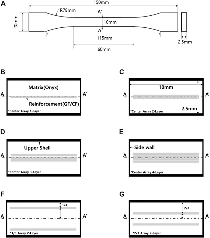
FIGURE 1. Composite specimen geometry and cross section. (A) Tensile test specimen shape, (B) 1-layer reinforcement, (C) 2-layer reinforcement, (D) 3-layer reinforcement, (E) 4-layer reinforcement, (F) 1/3 Arrangement of reinforcement, (G) 2/3 Arrangement of reinforcement.
2.2 Layer arrangement
Table 1 shows the physical properties of the materials used in this study. The setting is shown in Figure 1, with the internal reinforcement arrangement based on the center of the specimen. As shown in Figures 1B–E, the output was set to be arranged from 1-layer to 4-layer according to the location of the center of each layer. Consequently, the reinforcement thickness becomes thicker with an increase in the number of reinforcement layers. To analyze the effective arrangement position of the fiber reinforcement instead of merely adjusting the center of the specimen, the tensile strength was compared and analyzed by setting the arrangement differently based on the location of the center under conditions that enable symmetry. Furthermore, the stacking arrangement of the internal reinforcement was varied; in one iteration, it was positioned at one-third the height of the upper shell from the centerline, as shown in Figure 1F. In another iteration, it was positioned at two-thirds the height of the upper shell from the centerline, as shown in Figure 1G. In all the experiments, the reinforcement was layered using the isotropic fiber method.
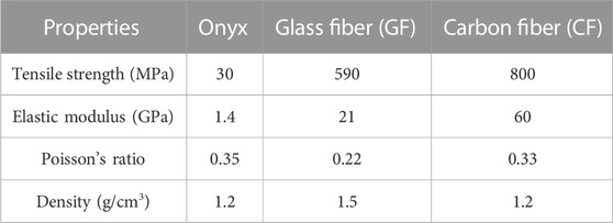
TABLE 1. Material properties.
2.3 3D printing conditions
The 3D printer used in this study was the mark-two by Markforged to print the composite material. The tensile test was performed by applying a tensile force at a tensile speed of 2 mm/min through a grip of 17.5 mm, according to the test standard. Each specimen was printed seven times, and the average value was calculated and compared, excluding the maximum and minimum values that differed the most from the average value. Finally, the specimen most similar to the average value was selected and analyzed.
3 Results and discussion
In this study, the mechanical strength of onyx-based composites printed using a 3D printing process was investigated. The composite material specimens comprising a matrix of onyx and reinforcement layers of GF and CF were fabricated using a 3D printing process and subsequently analyzed. The results of the tensile tests on the various specimens are shown in Figure 2. As the shape of the specimen, after the tensile test, was similar, regardless of the reinforcements, only the results of the specimens reinforced with CF are presented here. After the tensile test, the cross-sections of all the specimens formed within their gauge length exhibited a similar tendency. Therefore, the results of the tensile test are valid.
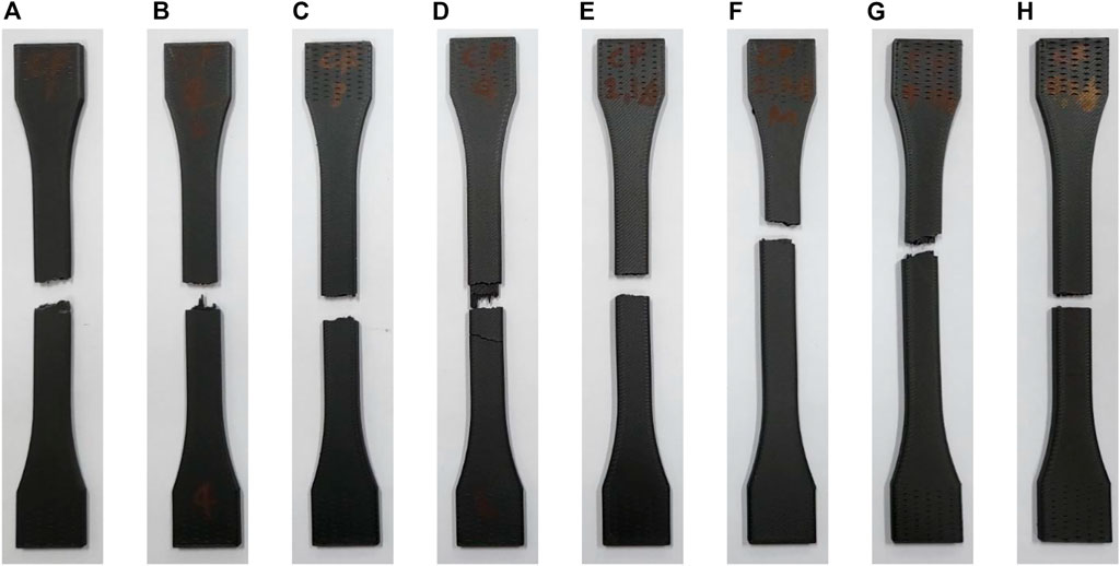
FIGURE 2. Shape after tensile test of composite material specimen using carbon fiber as reinforcement (A) 1-layer reinforcement, (B) 2-layer reinforcement, (C) 3-layer reinforcement, (D) 4-layer reinforcement, (E) 1/3 Arrangement of 2-layer reinforcement, (F) 2/3 Arrangement of 2-layer reinforcement, (G) 1/3 Arrangement of 4-layer reinforcement, (H) 2/3 Arrangement of 4-layer reinforcement.
Figure 3 shows the tensile test results according to the thickness of the GF and CF reinforcements inside the composite material. The composite material of onyx mixed with 1-layer GF experienced a tensile force of 1308.7 N. In the specimen with a 4-layer GF arrangement, the tensile force was found to be 2867.3 N. In the specimen of onyx mixed with CF, the tensile force was 1271.1 N and 3797.0 N for 1-layer and 4-layer CF, respectively. In other words, the tensile force increases as the reinforcement layer inside onyx becomes thicker. In addition, the composite materials with a 1-layer reinforcement of either CF or GF did not experience significantly different tensile forces. However, as the thickness of the reinforcement increased, CF-reinforced onyx exhibited a considerably higher tensile strength. As shown in Table 1, the larger increase in tensile strength can be attributed to the elastic modulus and tensile strength of CF, which are higher than those of GF. In general, the change in elastic properties of composite materials appears to depend on the volume fraction of the matrix material and the fiber material (Zhou et al., 2017; Makarian and Santhanam, 2020; Yun et al., 2022a; Yun et al., 2022b; Yun et al., 2022c). As the volume fraction increases, i.e., as the thickness of the reinforcement inside the composite material increases, the strength of the composite material increases. Therefore, high-strength components can be printed by increasing the ratio of the reinforcement inside the composite material.
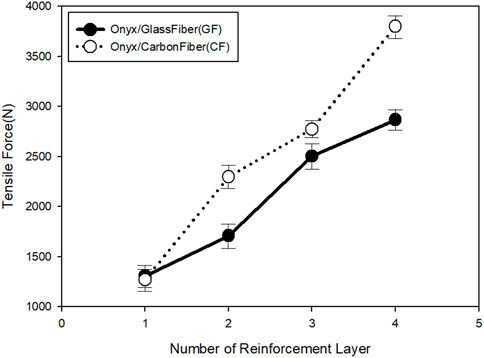
FIGURE 3. Tensile force according to the type of reinforcement and number of layers.
Figure 4 shows the displacement of the specimen according to the tensile test. In the onyx/GF composite material specimen, when the reinforcement GF was included in 1 layer, the gauge length increased by 5.2 mm compared to 50 mm in the specimen without reinforcement. The specimen containing 4-layer GF exhibited a displacement increase of 8.1 mm. In the onyx/CF composite material specimen containing 1-layer CF, the displacement increased by 5.2 mm compared to 50 mm in the specimen without reinforcement but increased by only 4.1 mm in the specimen containing 4-layer CF. No significant difference in displacements was observed after 2-layer CF. This can be attributed to the difference in physical properties of elastic modulus and tensile strength between CF and GF. As the modulus of elasticity is the ratio of the strain to tensile strength, the strain experienced by CF is less because the elastic modulus and tensile strength of CF are higher than those of GF. Therefore, as the number of fiber reinforcement layers inside the composite material increases, the volume fraction of the reinforcement increases, thereby strengthening its effect. Consequently, the composite stiffness increases and its flexibility decreases with increasing CF content.
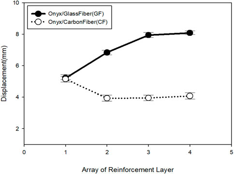
FIGURE 4. Specimen displacement according to the type of reinforcement and number of layers.
Figure 5 shows the stress-strain curve according to the number of reinforcement layers. In the onyx/GF specimens, the tensile strength increased as the GF layer became thicker. As shown in Figure 3, the tensile stress applied at the cross-section of the specimen increases as the tensile force of the composite material increases. From Figure 4 and Figure 5, higher specimen displacements correspond to higher strains. In contrast, as the thickness of CF increased in the Onyx/CF specimen, the tensile strength increased, but the strain increased only marginally. The reason for this is related to the Poisson’s ratio and strain of the CF. As the number of CF layers increases, the influence of the CF increases. In general, materials with high strain can be printed using onyx/GF composites but the increase in tensile strength is limited. Conversely, materials with high tensile strength can be manufactured by 3D printing using onyx/CF composites; however, the strain rate is limited.
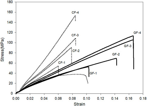
FIGURE 5. Stress-Strain curve depending on the number of reinforcement layers.
Tests were conducted on various arrangements of the reinforcement to analyze their effect on the properties of the specimen. Interestingly, the 2-layer reinforcement could be arranged symmetrically based on the center of the cross-section of the tensile test specimen. Consequently, the specimen was printed by stacking the reinforcement at one-third the height of the upper shell from its outer boundary. Another specimen was printed by laminating the reinforcement at two-thirds the height of the upper shell from its outer boundary. Figure 6 shows the tensile force according to the arrangement of the 2-layer reinforcement. The lowest and highest tensile forces were measured when the reinforcement was concentrated at the center and when it was arranged at two-thirds the height of the upper shell from its outer boundary, respectively. In the onyx/GF composite specimen, tensile forces of 1709 N, 2150 N, and 2470 N were measured when the reinforcement was concentrated in the center, layered at one-third height, and at two-thirds the height, respectively. The corresponding tensile forces for the onyx/CF composite specimen were 2296 N, 2579 N, and 2644 N, respectively. This increase in tensile strength can be attributed to the increase in the area where the GF and CF reinforcement layers are in contact with onyx, resulting in a larger tensile force. In general, the main variables of tensile force and tensile strength in composite materials are the bonding force and bonding area between the matrix and reinforcement (Joseph et al., 1996; Zhang et al., 2011). Therefore, the effect of the reinforcement is optimal only when it is mixed with the matrix at an appropriate interval. The results of analyzing the extent of displacement according to the tensile test, shown in Figure 7, are as follows. In the onyx/GF composite specimen, a displacement of 6.8 mm occurred when the reinforcement was arranged in the center. When the GF layer was arranged at one-third or two-third heights, the displacement increased by 0.4 mm–7.2 mm. The onyx/CF composite specimens showed a 0.5 mm decrease in displacement from 3.9 mm to 3.4 mm. This difference in displacement can be attributed to the difference in the Poisson’s ratio and elongation of CF fiber. The stress-strain curves of onyx-based composites from the tensile test were compared, as shown in Figure 8. The comparison shows that arranging the reinforcement near the surface of the specimen improves its tensile strength, confirming that the elongation of the composite material is affected by the physical properties of the reinforcement.
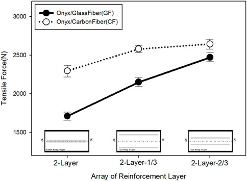
FIGURE 6. Tensile force according to the position of 2-layer reinforcement.
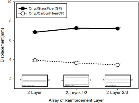
FIGURE 7. Specimen displacement according to the position of 2-layer reinforcement.
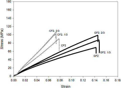
FIGURE 8. Stress-Strain curve depending on the position of 2-layer reinforcement.
In addition, the tensile test results of the 4-layer laminated composite material specimens were compared and analyzed. From Figure 9, the 4-layer reinforcement experiences the highest tensile force. In the onyx/GF 4-layer tensile test specimen, tensile forces of 2860 N, 2787 N, and 3204 N were measured when the reinforcement was concentrated in the center, layered at one-third height, and at two-thirds the height, respectively. The corresponding tensile forces for the 4-layer onyx/CF tensile test specimens were 3797 N, 3739 N, and 3854 N, respectively. Figure 10 shows the results of measuring specimen displacement according to the tensile test; the 4-layer composite material specimens do not exhibit significant differences in displacement. In other words, composite material 3D printing output containing four layers of reinforcement or more is greatly influenced by the reinforcement, confirming that displacement is governed by the physical properties of the fiber. Analyses of the stress-strain curves according to the tensile test are shown in Figure 11. In the onyx/GF composite tensile test specimens, changes in tensile strength were observed according to the arrangement. When the GF reinforcement is arranged outside the composite material, higher tensile strength is exhibited. However, in the onyx/CF specimens, the position and arrangement of the reinforcement did not have a significant effect when four layers of CF were laminated. This indicates that the effect of the reinforcement is strengthened as the volume fraction of the reinforcement inside onyx and the number of laminated layers increase, independent of location and arrangement. Therefore, when printing a composite material part using 3D printing, the volume fraction or specific gravity of the reinforcement must be increased to increase the tensile strength and tensile force. For a given quantity of reinforcement, arranging it close to the outer wall of the composite gives the best results in terms of strength.
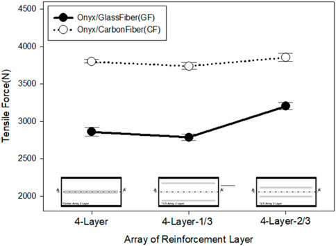
FIGURE 9. Tensile force according to the position of 4-layer reinforcement.
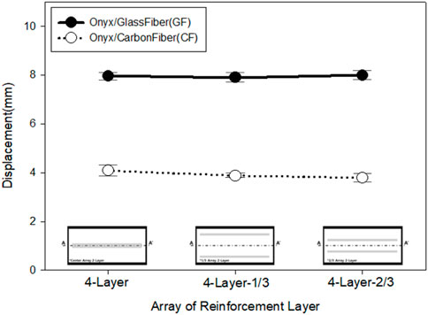
FIGURE 10. Specimen displacement according to the position of 4-layer reinforcement.
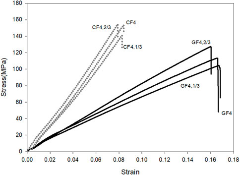
FIGURE 11. Stress-Strain curve according to the position of 4-layer reinforcement.
4 Conclusion
In this study, the mechanical strength of 3D-printed onyx-based composites was evaluated. The composite comprised a matrix of onyx reinforced with laminated layers of either GF or CF. The evaluation was performed according to the specifications in ISO 527-4, which stipulates an internal filling of 30%. The number of reinforcement layers, formed using either GF or CF, was set from 1 to 4 in consideration of the output conditions of the composite material specimen. Furthermore, the 2-layer and 4-layer reinforcements were symmetrically set inside onyx to compare and analyze the mechanical strength according to the arrangement of the reinforcements. To analyze the effect of internal stiffeners in composite 3D printed parts based on previous studies, we set up different layers of internal stiffeners (Cofaru et al., 2021; Ojha et al., 2022; Ramezani Dana et al., 2022) While the specimens with 1-layer GF and CF exhibited no significant difference in tensile force, it increased as the number of GF or CF layers increased up to 4. The reinforcement effect of CF exceeded that of GF as the number of layers increased. The displacement exhibited by the composite material specimens increased as the number of layers increased in the GF-reinforced specimens. However, in the CF-reinforced specimens, the displacement decreased. This discrepancy can be attributed to the characteristics of the fiber reinforcement used inside onyx; as the number of fiber reinforcement layers increases, the effect of the fiber strengthens. In addition, arranging the reinforcement in the center results in the most optimal combination of physical properties in the final product. Furthermore, layering the matrix and reinforcement sequentially results in the highest values of tensile strength. The results of our study show that the arrangement and thickness of reinforcement layers are crucial factors in obtaining the desired physical properties in 3D-printed composites. Therefore, a database that summarizes the various combinations of arrangement and thickness and their effects will considerably aid the optimization of composite material 3D printing.
Data availability statement
The raw data supporting the conclusion of this article will be made available by the authors, without undue reservation.
Author contributions
Formal analysis, Investigation, G-WL; Resources, Data curation, T-HK; Conceptualization, J-HY; Writing—original draft, N-JK; Writing—review and editing, K-HA; Writing—original draft preparation, supervision, M-SK. All authors have read and agreed to the published version of the manuscript.
Funding
This research was supported by “Regional Innovation Strategy (RIS)” through the National Research Foundation of Korea (NRF) funded by the Ministry of Education (MOE): (2021RIS-004) This work was supported by National Research Foundation of Korea (NRF) grants funded by the Korean government (MSIT): NRF 2022R1G1A1004962.
Acknowledgments
This is a short text to acknowledge the contributions of specific colleagues, institutions, or agencies that aided the efforts of the authors.
Conflict of interest
Author N-JK was employed by JinSung Boltech Corporation.
The remaining authors declare that the research was conducted in the absence of any commercial or financial relationships that could be construed as a potential conflict of interest.
Publisher’s note
All claims expressed in this article are solely those of the authors and do not necessarily represent those of their affiliated organizations, or those of the publisher, the editors and the reviewers. Any product that may be evaluated in this article, or claim that may be made by its manufacturer, is not guaranteed or endorsed by the publisher.
References
Araya-Calvo, M., López-Gómez, I., Chamberlain-Simon, N., León-Salazar, J. L., Guillén-Girón, T., Corrales-Cordero, J. S., et al. (2018). Evaluation of compressive and flexural properties of continuous fiber fabrication additive manufacturing technology. Addit. Manuf. 22, 157–164. doi:10.1016/j.addma.2018.05.007
Awad, A., Fina, F., Goyanes, A., Gaisford, S., and Basit, A. W. (2020). 3D printing: Principles and pharmaceutical applications of selective laser sintering. Int. J. Pharm. 586, 119594. doi:10.1016/j.ijpharm.2020.119594
Bárnik, F., Vaško, M., Handrik, M., Dorčiak, F., and Majko, J. (2019). Comparing mechanical properties of composites structures on Onyx base with different density and shape of fill. Transp. Res. Procedia 40, 616–622. doi:10.1016/j.trpro.2019.07.088
Cheng, Y., Shi, X., Jiang, X., Wang, X., and Qin, H. (2020). Printability of a cellulose derivative for extrusion-based 3D printing: The application on a biodegradable support material. Front. Mater. 7, 86. doi:10.3389/fmats.2020.00086
Cofaru, N. F., Pascu, A., Oleksik, M., and Petruse, R. (2021). Tensile properties of 3D-printed continuous-fiber-reinforced plastics. Mater. Plast. 58 (4), 271–282. doi:10.37358/mp.21.4.5552
Eisenberg, M., Hsi, S., and Oh, H. (2013). Machines and minds: The new cognitive science, and the potential evolution of children’s intuitions about thinking. Int. J. Child-Computer Interact. 14, 1–4. doi:10.1016/j.ijcci.2017.06.001
El-Tayeb, N. S., and Gadelrab, R. M. (1996). Friction and wear properties of E-glass fiber reinforced epoxy composites under different sliding contact conditions. Wear 192 (1-2), 112–117. doi:10.1016/0043-1648(95)06770-1
Fina, F., Goyanes, A., Gaisford, S., and Basit, A. W. (2017). Selective laser sintering (SLS) 3D printing of medicines. Int. J. Pharm. 529 (1-2), 285–293. doi:10.1016/j.ijpharm.2017.06.082
Galati, M., Viccica, M., and Minetola, P. (2021). A finite element approach for the prediction of the mechanical behaviour of layered composites produced by Continuous Filament Fabrication (CFF). Polym. Test. 98, 107181. doi:10.1016/j.polymertesting.2021.107181
Joseph, K., Varghese, S., Kalaprasad, G., Thomas, S., Prasannakumari, L., Koshy, P., et al. (1996). Influence of interfacial adhesion on the mechanical properties and fracture behaviour of short sisal fibre reinforced polymer composites. Eur. Polym. J. 32 (10), 1243–1250. doi:10.1016/s0014-3057(96)00051-1
Kabandana, G. K. M., Zhang, T., and Chen, C. (2022). Emerging 3D printing technologies and methodologies for microfluidic development. Anal. Methods 14, 2885–2906. doi:10.1039/d2ay00798c
Kollamaram, G., Croker, D. M., Walker, G. M., Goyanes, A., Basit, A. W., and Gaisford, S. (2018). Low temperature fused deposition modeling (FDM) 3D printing of thermolabile drugs. Int. J. Pharm. 545 (1-2), 144–152. doi:10.1016/j.ijpharm.2018.04.055
Kriz, R. D., and Stinchcomb, W. W. (1979). Elastic moduli of transversely isotropic graphite fibers and their composites. Exp. Mech. 19 (2), 41–49. doi:10.1007/bf02324524
Le Tohic, C., O'Sullivan, J. J., Drapala, K. P., Chartrin, V., Chan, T., Morrison, A. P., et al. (2018). Effect of 3D printing on the structure and textural properties of processed cheese. J. Food Eng. 220, 56–64. doi:10.1016/j.jfoodeng.2017.02.003
Makarian, K., and Santhanam, S. (2020). Micromechanical modeling of thermo-mechanical properties of high volume fraction particle-reinforced refractory composites using 3D Finite Element analysis. Ceram. Int. 46 (4), 4381–4393. doi:10.1016/j.ceramint.2019.10.162
Manapat, J. Z., Chen, Q., Ye, P., and Advincula, R. C. (2017). 3D printing of polymer nanocomposites via stereolithography. Macromol. Mater. Eng. 302 (9), 1600553. doi:10.1002/mame.201600553
Martín-Montal, J., Pernas-Sánchez, J., and Varas, D. (2021). Experimental characterization framework for SLA additive manufacturing materials. Polymers 13 (7), 1147. doi:10.3390/polym13071147
Mei, H., Ali, Z., Yan, Y., Ali, I., and Cheng, L. (2019). Influence of mixed isotropic fiber angles and hot press on the mechanical properties of 3D printed composites. Addit. Manuf. 27, 150–158. doi:10.1016/j.addma.2019.03.008
Montero, M., Roundy, S., Odell, D., Ahn, S. H., and Wright, P. K. (2001). Material characterization of fused deposition modeling (FDM) ABS by designed experiments. Soc. Manuf. Eng. 10 (13552540210441166), 1–21.
Morales, M. A., Atencio Martinez, C. L., Maranon, A., Hernandez, C., Michaud, V., and Porras, A. (2021). Development and characterization of rice husk and recycled polypropylene composite filaments for 3D printing. Polymers 13 (7), 1067. doi:10.3390/polym13071067
Morales, U., Esnaola, A., Iragi, M., Aretxabaleta, L., and Aurrekoetxea, J. (2021). The effect of cross-section geometry on crushing behaviour of 3D printed continuous carbon fibre reinforced polyamide profiles. Compos. Struct. 274, 114337. doi:10.1016/j.compstruct.2021.114337
Moreno-Núñez, B. A., Abarca-Vidal, C. G., Treviño-Quintanilla, C. D., Sánchez-Santana, U., Cuan-Urquizo, E., and Uribe-Lam, E. (2023). Experimental analysis of fiber reinforcement rings’ effect on tensile and flexural properties of onyx™–kevlar® composites manufactured by continuous fiber reinforcement. Polymers 15 (5), 1252. doi:10.3390/polym15051252
Newcomb, B. A. (2016). Processing, structure, and properties of carbon fibers. Compos. Part A Appl. Sci. Manuf. 91, 262–282. doi:10.1016/j.compositesa.2016.10.018
Ojha, K. K., Gugliani, G., and Francis, V. (2022). “Tensile properties and failure behaviour of continuous kevlar fibre reinforced composites fabricated by additive manufacturing process,” in Advances in materials and processing technologies, 1–15. doi:10.1080/2374068x.2022.2106655
Parmiggiani, A., Prato, M., and Pizzorni, M. (2021). Effect of the fiber orientation on the tensile and flexural behavior of continuous carbon fiber composites made via fused filament fabrication. Int. J. Adv. Manuf. Technol. 114 (7), 2085–2101. doi:10.1007/s00170-021-06997-5
Pisanu, L., Santiago, L. C., Barbosa, J. D. V., Beal, V. E., and Nascimento, M. L. F. (2021). Effect of the process parameters on the adhesive strength of dissimilar polymers obtained by multicomponent injection molding. Polymers 13 (7), 1039. doi:10.3390/polym13071039
Rahim, T. N. A. T., Abdullah, A. M., and Md Akil, H. (2019). Recent developments in fused deposition modeling-based 3D printing of polymers and their composites. Polym. Rev. 59 (4), 589–624. doi:10.1080/15583724.2019.1597883
Ramezani Dana, H., El Mansori, M., Barrat, M., and Seck, C. A. (2022). Tensile behavior of additively manufactured carbon fiber reinforced polyamide-6 composites. Polymer-Plastics Technol. Mater. 61 (6), 624–641. doi:10.1080/25740881.2021.2005094
Shirazi, S. F. S., Gharehkhani, S., Mehrali, M., Yarmand, H., Metselaar, H. S. C., Kadri, N. A., et al. (2015). A review on powder-based additive manufacturing for tissue engineering: Selective laser sintering and inkjet 3D printing. Sci. Technol. Adv. Mater. 16 (3), 033502. doi:10.1088/1468-6996/16/3/033502
Sun, B., and Wu, L. (2022). Research progress of 3D printing combined with thermoplastic foaming. Front. Mater. 9, 1083931. doi:10.3389/fmats.2022.1083931
Tee, Y. L., Peng, C., Pille, P., Leary, M., and Tran, P. (2020). PolyJet 3D printing of composite materials: Experimental and modelling approach. Jom 72 (3), 1105–1117. doi:10.1007/s11837-020-04014-w
Tian, J., Zhang, R., Yang, J., Chou, W., Xue, P., and Ding, Y. (2021). Additive manufacturing of wood flour/PHA composites using micro-screw extrusion: Effect of device and process parameters on performance. Polymers 13 (7), 1107. doi:10.3390/polym13071107
Wang, J., Goyanes, A., Gaisford, S., and Basit, A. W. (2016). Stereolithographic (SLA) 3D printing of oral modified-release dosage forms. Int. J. Pharm. 503 (1-2), 207–212. doi:10.1016/j.ijpharm.2016.03.016
Yan, X., Bethers, B., Chen, H., Xiao, S., Lin, S., Tran, B., et al. (2021). Recent advancements in biomimetic 3d printing materials with enhanced mechanical properties. Front. Mater. 8, 518886. doi:10.3389/fmats.2021.518886
Yun, J. H., Jeon, Y. J., and Kang, M. S. (2022b). Analysis of elastic properties of polypropylene composite materials with ultra-high molecular weight polyethylene spherical reinforcement. Materials 15 (16), 5602. doi:10.3390/ma15165602
Yun, J. H., Jeon, Y. J., and Kang, M. S. (2022a). Numerical investigation of the elastic properties of polypropylene/ultra high molecular weight polyethylene fiber inside a composite material based on its aspect ratio and volume fraction. Polymers 14 (22), 4851. doi:10.3390/polym14224851
Yun, J. H., Jeon, Y. J., and Kang, M. S. (2022c). Prediction of elastic properties using micromechanics of polypropylene composites mixed with ultrahigh-molecular-weight polyethylene fibers. Molecules 27 (18), 5752. doi:10.3390/molecules27185752
Zhang, Y., Luo, R., Zhang, J., and Xiang, Q. (2011). The reinforcing mechanism of carbon fiber in composite adhesive for bonding carbon/carbon composites. J. Mater. Process. Technol. 211 (2), 167–173. doi:10.1016/j.jmatprotec.2010.08.028
Keywords: composite, 3D printing, Onyx, carbon fiber, glass fiber
Citation: Lee G-W, Kim T-H, Yun J-H, Kim N-J, Ahn K-H and Kang M-S (2023) Strength of Onyx-based composite 3D printing materials according to fiber reinforcement. Front. Mater. 10:1183816. doi: 10.3389/fmats.2023.1183816
Received: 10 March 2023; Accepted: 18 April 2023;
Published: 28 April 2023.
Edited by:
Jianlei Wang, Chinese Academy of Sciences (CAS), ChinaReviewed by:
Enrique Cuan-Urquizo, Monterrey Institute of Technology and Higher Education (ITESM), MexicoNidhin Divakaran, Central Institute of Plastics Engineering and Technology, India
Copyright © 2023 Lee, Kim, Yun, Kim, Ahn and Kang. This is an open-access article distributed under the terms of the Creative Commons Attribution License (CC BY). The use, distribution or reproduction in other forums is permitted, provided the original author(s) and the copyright owner(s) are credited and that the original publication in this journal is cited, in accordance with accepted academic practice. No use, distribution or reproduction is permitted which does not comply with these terms.
*Correspondence: Min-Soo Kang, S2FuZzEwMTAxQHN1bm1vb24uYWMua3I=