 Ying-Ying Xue
 Xing-Gang Wang2
 Fei Cai
- 1Earthquake Administration of Jiangsu Province, Nanjing, China
- 2Nanjing Hydraulic Research Institute (NHRI), Nanjing, China
- 3Department of Environmental Engineering Science, Gunma University, Kiryo, Japan
It is reported that the inclined pile could be either beneficial or detrimental for the abutment they support in the condition of liquefaction—induced lateral displacement. To clarify the effect of inclined pile on seismic response of bridge abutments undergoing liquefaction—induced lateral displacement, numerical analyses were carried out on the damaged abutment that was supported by inclined piles and that was displaced riverwards 100 mm–150 mm due to soil liquefaction during 2011 Great East Japan earthquake. Accordingly, a fully coupled dynamic effective stress finite element model was developed for the soil—pile—superstructure system. It was found that the shear failure of the bridge abutment was initialized from the inclined piles and then followed by the middle vertical pile. Moreover, the earthquake—induced liquefaction caused substantial lateral displacement of soils around the piles and thus dominated the backward rotation of the abutments supported by inclined piles. Additionally, the exclusion of the deck pinning effect may lead to a marked increase in the lateral displacement and rotation of abutments. If the abutment were supported by vertical piles, a much larger lateral displacement was expected and the promotion of the earth pressure behind the abutment was the main cause of the forward rotation of the piled abutment.
1 Introduction
The safety of the soil-pile -bridge system is a primary concern in the engineering practice (Gerolymos et al., 2008; Cubrinovski et al., 2014; Qu et al., 2018a; Qu et al., 2018b; Qu et al., 2019). Liquefaction—induced lateral displacement has caused much damage to the piled abutment of bridges in the past earthquakes, such as the 1991 Costa Rica Earthquake, the 2011 Christchurch earthquake, and the 2011 Great East Japan earthquake (Gerolymos et al., 2008; Cubrinovski et al., 2014; National Institute for Land and Infrastructure Management of Japan, Public Works Research Institute of Japan, 2014; Tazohb et al., 2008; Xu et al., 2023). It is reported that the inclined piles are more effective than vertical piles in restricting lateral displacements of superstructures subjected to liquefaction induced lateral displacement. However, the evidence shows that the inclined pile could be either beneficial or detrimental for the abutment they support in the condition of liquefaction—induced lateral displacement (Gerolymos et al., 2008; Cubrinovski et al., 2014). For example, the liquefaction—induced lateral displacement caused a lateral displacement of approximately 1–2 m at the unconstrained river banks in the vicinity of South Brighton Bridge during the 2011 Christchurch earthquake. As a result, the bridge abutment rotated by 8° and the pile head displaced laterally approximately 20 cm. Nevertheless, following the infilling of the offsets between the approaches and the deck, the bridge was back in service immediately after the earthquake (Cubrinovski et al., 2014). However, a detrimental case related to the bridge abutment supported by inclined piles were found on Rio Vizcaya Bridge during the 1991 Costa Rica Earthquake. The liquefaction—induced lateral displacement caused large rotations of the abutment and thus the collapse of the bridge deck (Gerolymos et al., 2008). Thus, it is necessary to clarify the damage mechanism of inclined piles which support the abutment subjected to the liquefaction—induced lateral displacement.
The liquefaction effects on piled bridge abutments have been investigated via both model tests and numerical analyses in recent years. Armstrong et al. (2013) conducted centrifuge model tests to evaluate the capability of the vertical pile group in resist the lateral displacement of abutments in approach embankments underlain by liquefied soils. The benefit of the pile pinning effect was reflected in reducing the lateral displacement of bridge abutments and was also evaluated by 2D numerical analyses. Tanabe et al. (2016) reported two case histories of two bridge abutments supported by inclined and vertical piles and subjected to a varying degree of damage due to liquefaction-induced lateral displacement during the 2011 Great East Japan earthquake. A 2D numerical model was developed to investigate the liquefaction effects. However, the effect of the superstructure (i.e., deck) wasn’t considered in the above analyses. Cubrinovski et al. (2014) found that the deck pinning contributes significantly to the back rotation of the piled abutment of short-span bridges in the case of liquefaction—induced lateral displacement; Nakata et al. (2018) used a large shaking table (i.e., E-Defense) facility to investigate both the liquefaction effect and the deck pinning effect on the bridge abutment supported by the vertical piles. Shin et al. (2008) and Wang et al. (2018) pointed out that appropriate modeling of soil-pile-deck interaction is necessary for understanding of the seismic response of bridge abutments, especially when the abutment piles encounter the problem of the liquefaction-induced lateral displacement. However, very limited work was conducted to investigate the effect of inclined pile on seismic response of bridge abutments undergoing liquefaction—induced lateral displacement, especially the soil-inclined pile-deck interaction effect. Incorporating the soil-inclined pile-deck interaction in the analyses could help understanding the damage mechanism of inclined piles of bridge abutments in the liquefaction induced lateral displacement ground.
For this purpose, this study performed a case study of damaged abutments which were supported by the pile group consisting of inclined piles and vertical piles and were displaced riverwards due to the liquefaction induced—lateral displacement during the 2011 Great East Japan earthquake. A 2D fully coupled dynamic effective stress model was developed for the soil -pile-bridge system. Accordingly, the damage mechanism of the bridge abutment and the effect of deck and pile rake angle on the seismic response of the bridge abutment were investigated.
2 Case history
Nishikawa Bridge was located in Miyagi Prefecture, Japan. The construction of the bridge was completed in the year of 1968. The bridge had a total length of 105 m and a width of 7.2 m. The bridge had three spans and each of span has length of 34.3 m. The total load of one-span deck was estimated to be 2,300 kN (Tanabe et al., 2016). During the 2011 Great Eastern Japan Earthquake, the A1 and A2 abutments of the bridge was horizontally displaced riverwards approximately 150 mm and 100 mm, respectively (see Figure 1), as reported by National Institute for Land and Infrastructure Management of Japan, Public Works Research Institute of Japan (2014). It was also reported that shear failure developed near the bottom of two abutments. The foundation of each abutment was composed of 7 * 3 reinforced concrete piles. The piles in the middle row were vertical, while others were inclined piles with rake angle of 10°. The pier foundation had 5 * 5 reinforced concrete piles: the piles in the front and rear rows were inclined at 10°, while the piles were vertical in the middle row. The diameter of the pile was 400 mm. The length of the pile was 7.0 m and 5.0 m for the abutment and the pier, respectively.
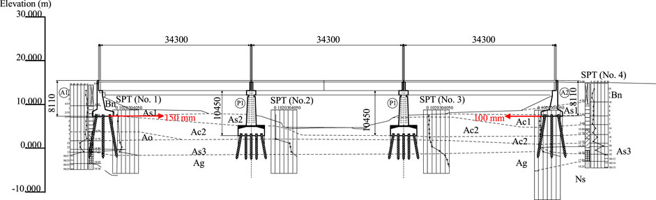
FIGURE 1. Side view of Nishikawa Bridge located in Miyagi Prefecture, Japan with geological cross section and standard penetration test data (unit: mm; Bs, Bn: Fills; As1: sand; Ac, Ao1, Ao2, Asc: clayey soil; Ag: sandy gravel; Ns: sandy soil).
3 Finite element modeling of the soil–pile—Bridge system
3.1 u-p formulation
Biot’s u-p formulations are used for saturated soils the dynamic system, where u and p represent the displacement and excess pore water pressure, respectively (Zienkiewicz et al., 1999):
where M is the mass matrix, u is the displacement vector, C is Rayleigh damping matrix, K is the stiffness matrix, Q is the coupled matrix, p is the excess pore water pressure vector, fu is the external load vector, H is the seepage matrix, S is the compression matrix, and fp is the external load vector for the pore water.
Biot’s u-p formulations had been implemented in a fully coupled dynamic effective stress finite element (FE) analysis software program UWLC (Forum 8 Co Ltd, 2005; Xu et al., 2013; Xu et al., 2021; Cai, 2020) where were employed for numerical analyses in this study. In this program, Eq. 2 can also be deactivated for layers where the excess pore water pressure is not necessarily calculated.
In the dynamic analysis, the matrix C was given by
where α and β are coefficients and are taken as 0.172 and 0.00174, respectively (Forum 8 Co Ltd, 2005; Wakai and Ugai, 2004). The coefficients α and β are related to damping ratio ξ and two periods T. In this study, ξ = 0.03, T1 = 0.2 s, and T1 = 2.0 s, as suggested by Xu et al. (2023).
3.2 Finite element model
In this study, a 2D finite element model was developed for the soil–pile—bridge (SPB) system, as shown in Figure 2. The soil layers were determined with some simplifications from the geological cross section shown in Figure 1. In this model, eight-node quadrilateral element was used for the soil, the abutment, and the pier. The abutment and the pier were modelled as elastic materials with unit weight of 24.5 kN/m3, Young’s modulus of 30 GPa, and Poison’s ratio of 0.15.
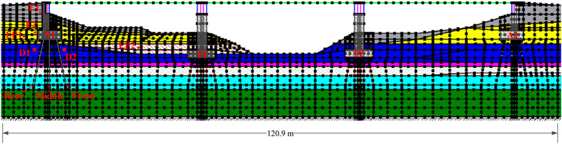
FIGURE 2. Finite element model for the soil–pile—bridge system.
The pile and the deck were modelled as Euler-Bernoulli beam. Table 1 gives the input parameters for the pile and the deck in the finite element analysis. In the 2D finite element model, the cross-sectional area and the cross-sectional inertia moment of piles were estimated according to Xu et al. (2013). The non-linearity of the pile was considered by using a bilinear model. The second Young’s modulus of piles was assumed to be 1% of the fist Young’s modulus of piles. According to Tanabe et al. (2016), the yield stress was set to 184 kN m for the pile. The deck was modelled as elastic materials. All beam element nodes and quadrilateral element nodes were merged.
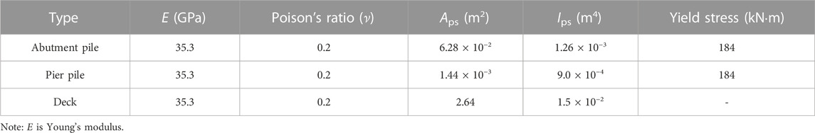
TABLE 1. Input parameters for the pile and the deck in the finite element analysis.
The bearing was modelled by shear springs to consider the dynamic interaction between the deck and the abutment/pier. For simply supported beam bridges, each deck was supported by a fixed bearing and an expansion bearing, which were described by linear and bi-linear shear springs, respectively. In this study. The initial stiffness of shear springs was taken as an empirical value of 6,600 kN/m (Wang et al., 2018). For bi-linear shear spring, the second stiffness was set to zero and the limit force was taken as 287.5 kN. The value of the limit force was estimated from the supported vertical load (i.e., 1,150 kN) multiplied by a friction coefficient. The friction coefficient was empirically taken as 0.25 (Wang et al., 2013).
3.3 Constitutive modeling of soils
Five standard penetration test (SPT) bore holes were drilled near either the abutment or the pier, as shown in Figure 1A. The SPT data were used to determine the liquefaction potential of each layer according to the Japanese Design Specifications of Highway Bridges (Japan Road Association, 2004; Towhata, 2008). Accordingly, liquefiable soils (i.e., Bs and As1) and non-liquefiable soils (i.e., Bn, Ao1, Ao2, Ac, Asc, Ag, and Ns) were classified.
A generalized plasticity model, named Pastor-Zienkiewicz Mark-Ⅲ (PZ) (Pastor et al., 1990), with some modifications by Cai et al. (2002) was adopted for the soils (Xu et al., 2023). Normally, the parameters for the PZ model were calibrated from either laboratory tests (e.g., cyclic triaxial undrained test) or in-situ tests. In this study, SPT data were used to determine the PZ model parameters. The liquefaction strength of two liquefiable layers (i.e., Bs and As1) was estimated according to according to the Japanese Design Specifications of Highway Bridges. The calculated liquefaction strength for Bs and As1 layers was given in Table 2, where N1 was taken as an average SPT blow count for Bs and As1 layers. The PZ model parameters (Ges0, Kev0, C, ms, mv, Mg, αg, Mf, αf, H0, β0, β1, γ0, HU0, γU) were determined to obtain the calculated liquefaction strength shown in Table 2. Table 3 presented the PZ model parameters for liquefiable layers. The hydraulic conductivities were taken as a typical value of 1.0 × 10⁻⁵ m/s for the liquefiable layers.
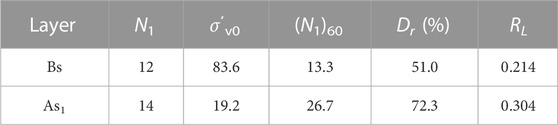
TABLE 2. Calculated liquefaction strength for Bs and As1 layers.
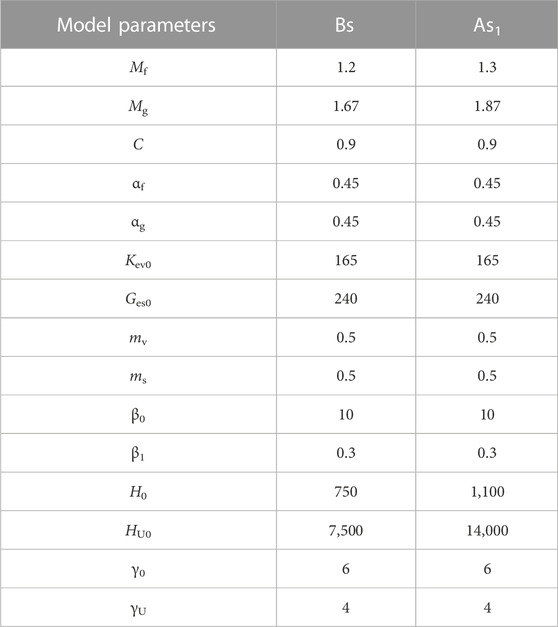
TABLE 3. Parameters of Pastor–Zienkiewicz III model for Bs and As1 layers.
A cyclic non-linear elastic constitutive model (Hardin and Drnevich, 1972), is used for non-liquefiable soils. The shear stress τ and the shear strain γ are described by a hyperbolic function:
where
τf is the shear strength which is a function of friction angle (φ) and cohesion (c) (Xu et al., 2013), G0 and m are model constants, Pa is atmospheric pressure, and p′ is the mean effective stress. Gmax at p′ = p′0 can be estimated from
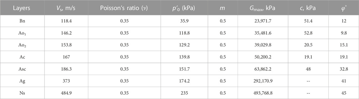
TABLE 4. Parameters of Hardin—Drnevich model for non-liquefiable layers.
3.4 Boundary conditions
In the UWLC program, the initial stress analysis was necessary to provide geostatic conditions for the earthquake analysis. Two lateral sides and the base of the analyzed model were fixed in the analyses. The two lateral sides were set at three times the total length of the bridge apart from each abutment. To investigate whether the finite element model could eliminate the boundary effect, a larger model with an additional 200 m on each side of the model was analyzed. The difference between the results obtained from these two models was minimal, indicating that the finite element model was acceptably accurate.
The seismic input was selected from the data recorded at the K-NET station (i.e., MYG009) nearest to Nishikawa Bridge during the 2011 Great Eastern Japan Earthquake. The seismic data can be downloaded from the website of National Research Institute for Earth Science and Disaster Resilience (https://www.kyoshin.bosai.go.jp/) after the required registration was completed. Tanabe et al. (2016) reported that the angle (θ0) of NS component of MYG009 and the longitudinal direction of the Nishikawa bridge was approximately 25°. Thus, the horizontal seismic input (
The UD component of MYG009 was taken as the vertical seismic input. Before the dynamic analyses, a baseline correction was conducted for the seismic recordings using SeismoSignal (SeismoSoft, 2013). Figures 3A, B showed the corrected horizontal and vertical input motions, respectively.
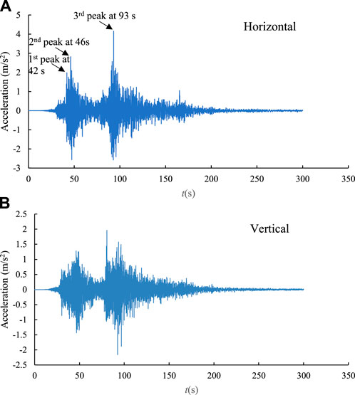
FIGURE 3. Seismic input for the soil—pile—bridge system: (A) Horizontal excitation and (B) vertical excitation.
4 Results and discussions
Table 5 gave the cases analyzed in this study. Specifically, the damage mechanism of the bridge abutment was investigated in the benchmark model, i.e., Case 1, as described in Section 3. Case 2 was used to study the effect of the deck on the seismic response of bridge abutments. Case 3 was used to investigate the effect of the pile rake angle on the seismic response of bridge abutments.
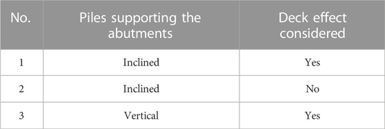
TABLE 5. The cases analyzed in this study.
4.1 Damage mechanism of the abutment supported by inclined piles
Figure 4 shows the time history of horizontal displacements at the head of piles supporting the abutments. All the piles displaced riverwards after the earthquake. The calculated maximum lateral displacement of piles reached 115 mm and 84 mm at the bottom of A1 and A2 abutments, respectively. The calculated residual lateral displacements were generally smaller than the observation; however, the simulation results overall reflected that the lateral displacement of pile at the bottom of A1 abutment was larger than that at the bottom of A1 abutment. This was due to the fact that the earthquake induces the full liquefaction not only in Bs layer, but also in As1 layer, (see Bs and As1 in Figure 2), consequently resulting in the instability of the slope of the river bank near the abutment. Figure 5 showed the excess pore water pressure (EPWP) ratio at two typical points (see EP1 and EP2 in Figure 2) in these two layers, where the EPWP ratio was defined as the ratio of EPWP to the initial effective vertical stress. The results indicated that the Bs and As1 layers were liquefied at approximately 43 s after the arrival of the first peak horizontal acceleration shown in Figure 3A. Moreover, the excess pore water pressure was developed much faster in Bs layer than that in As1 layer because the liquefaction strength of Bs layer was smaller (see Table 2).
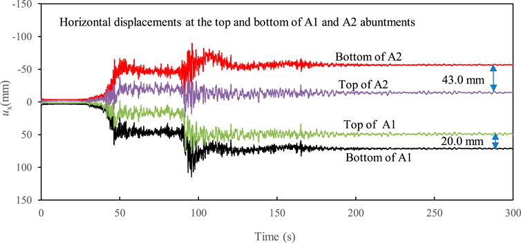
FIGURE 4. Time history of horizontal displacements at the top and bottom of two abutments, i.e., A1 and A2 (Case 1).
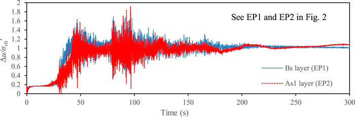
FIGURE 5. Time histories of the excess pore water pressure ratio at two typical points (see EP1 and EP2 in Figure 2).
Figure 4 further showed that the lateral displacements at the top of either A1 or A2 abutment were much smaller than those at the bottom of corresponding abutment, indicating that both A1 and A2 abutments rotated backwards. This phenomenon was also found for some abutments supported by inclined piles during the 2010–2011 Christchurch earthquakes where substantial slumping of the approaches was reported near these abutments due to soil liquefaction. The reason for the backward rotation of the abutment was probably because of the deck pinning of short-span bridges (Cubrinovski et al., 2014).
To investigate the effect of deck on the damage of the abutment, an additional case (i.e., Case 2) was analyzed assuming that the deck was removed from the benchmark model. Figure 6 showed that the exclusion of the deck pinning effect may lead to a marked increase in the lateral displacement and rotation of abutments, where ux,RA1 and ux,RA2 were the residual lateral displacements of A1 and A2 abutments, respectively, and θRA1 and θRA2 were the residual rotation angle of A1 and A2 abutments, respectively. Note that a clockwise rotation was considered as negative in this study. The results indicated that the abutments supported by inclined piles could rotate backwards even when the deck pinning effect was not considered in this study (see Figure 6). It was stressed that positive θRA1 and negative θRA2 indicated back rotation of A1 and A2 abutments, respectively. Based on the numerical results, the damage mechanism involving the back rotation of the abutment probably complied with the following process: 1) The earthquake—induced liquefaction initially caused substantial lateral displacement of soils around the piles, as shown by two typical points in Figure 7 (See D1 and D2 in Figure 2); 2) the inclined piles consequently had to rotate along the direction of arrows shown in Figure 8 under the liquefaction—induced lateral displacements; 3) and then the displaced inclined piles dominated the rotation of the abutments.
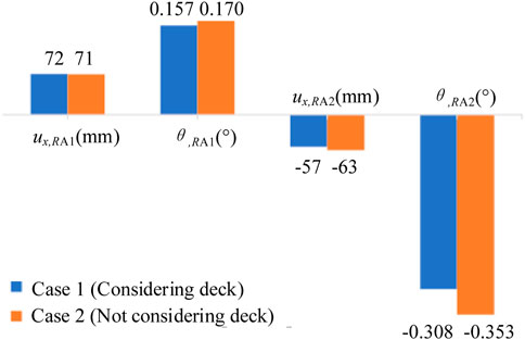
FIGURE 6. Effect of the deck on the residual lateral displacement and rotation of A1 and A2 abutments.
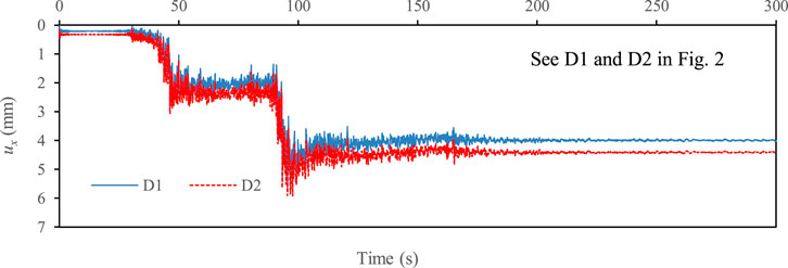
FIGURE 7. Time histories of two typical points (see D1 and D2 in Figure 2), representing the lateral displacement of soils in the vicinity of inclined piles in front and rear rows.
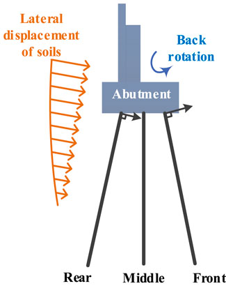
FIGURE 8. Mechanism of the abutment rotation supported by inclined piles under the liquefaction—induced lateral displacement.
Figure 9 showed the calculated maximum internal force of a single pile at different rows (i.e., front, middle, and rear), where Mmax, Smax, and Nmax were the maximum bending moment, shear force, and axial force, respectively. In general, the Mmax at different rows reached the ultimate value of 184 kN m at approximately 1.0 m–7.0 m away from the cap. At the pile head, Mmax was generally smaller than the ultimate value for all piles. However, the Smax peaked at the pile head. This result can explain why the shear failure has been developed at the pile head. In addition, the rear and front piles appeared to have the larger Mmax and Smax than the middle pile at the pile head, indicating that the shear failure was initialized from the inclined piles and then followed by the middle pile. Especially, the inclined piles sustained the Nmax three times more than the middle pile (see Figure 9C) during the earthquake. Thus, special treatments were necessary for inclined group piles in the engineering design to increase the shear capacity of the inclined pile, e.g., increasing the ratio of longitudinal reinforcement, reinforcement stirrup.
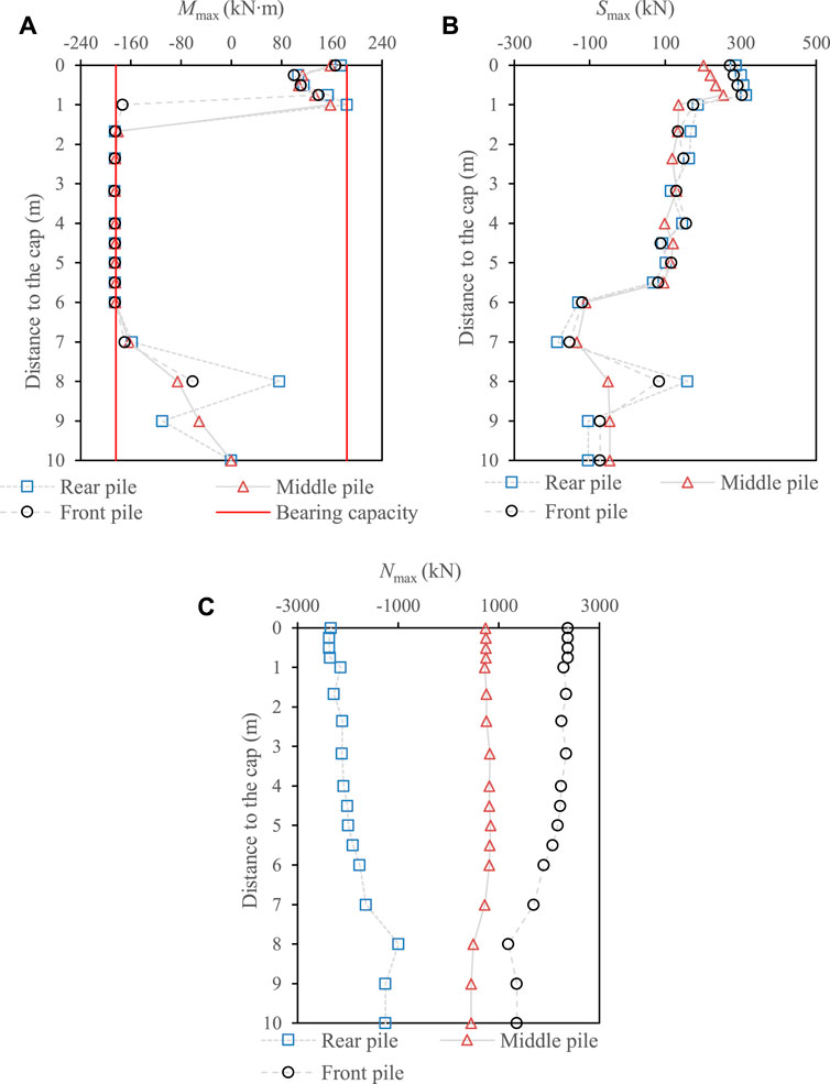
FIGURE 9. Distribution of the maximum internal force of a single pile at different rows (i.e., front, middle, and rear) (A) bending moment (Mmax), (B) shear force (Smax), and (C) axial force (Nmax) (Case 1).
4.2 Effect of the pile rake angle on the abutment damage
To investigate the effect of the pile rake angle on the lateral displacement at the bottom of A1 and A2 abutments, Case 3 was analyzed assuming that all piles supporting the abutments were vertical. Figure 10 showed the comparison of the lateral displacement at the bottom of A1 and A2 abutments between Cases 1 and 3. The results indicated that the pile rake angle had an insignificant effect on the lateral displacement of the abutment before the first peak horizontal acceleration was reached. However, the lateral displacement in at the bottom of the abutment in Case 1 turned to become much larger than that in Case 3, especially when the third peak horizontal acceleration was arrived at approximately 93 s. Moreover, the residual lateral displacement (ux,R) at the bottom of A1 and A2 abutments increased by approximately 82% and 45% in Case 3 with respect to that in Case 1, respectively. The above results demonstrated that the inclined piles were more effective than vertical piles in restricting the liquefaction—induced lateral displacements of the abutment during.
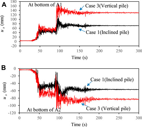
FIGURE 10. Effect of the pile rake angle on the lateral displacement at the bottom of (A) A1 and (B) A2 abutments.
To further investigate the effect of pile rake angle on the deformation of the abutment, Figure 11 compared the time histories of the rotation angle of the A1 abutment in Cases 1 and 3. The results indicated that the residual rotation angle of the abutment supported by vertical piles had opposite sign with respect to that of the abutment supported by inclined piles. Thus, the abutments in Case 3 rotated forwards and had different deformation mechanism with respect to the forementioned backward rotation of the abutment supported by inclined piles. Particularly, there was a tremendous increase in the rotation angle of the abutment in Case 3 when the third peak horizontal acceleration was reached. The forward rotation of the abutment in Case 3 was probably dominated by the promotion of the Earth pressure at the backfill of abutment, including the increase in the horizontal stress in non-liquefiable layer and the buildup of EPWP in liquefied layer. Specifically, Figures 12 showed the calculated horizontal stress (σxx) at two typical points (see E1 and E2 in Figure 2), representing the center of non-liquefiable and liquefiable layers behind the abutment in Case 3. The horizontal stress at the non-liquefiable layer increased abundantly during the earthquake and reached the maximum at the arrival of the third peak horizontal acceleration. The horizontal stress at the liquefiable layer decreased to a value approaching zero due to the soil liquefaction; however, the EPWP also reached the maximum value of 65 kPa at the time of third peak horizontal acceleration (see Figure 12). This maximum value was approximately five times more than the initial horizontal stress.
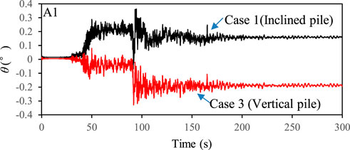
FIGURE 11. Effect of the pile rake angle on the rotation of the A1 abutment.
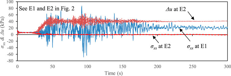
FIGURE 12. Time histories of horizontal stress (σxx) and excess pore water pressure (Δu) at typical points behind the A1 abutment (see E1 and E2 in Figure 2) (Case 3).
Figure 13A showed that the Mmax at pile head in Case 3 was approaching to the yield stress at different rows. Unlike inclined piles in Case 1, the values of Mmax and Smax were almost identical for vertical piles at different rows in Case 3 (see Figures 13A, B). This result indicated that all vertical piles not only displaced equally at the pile head, but also rotated equally due to the restriction of the abutment. Figure 13C indicated that the Nmax at the pile head in Case 3 was approximately 67%–78% of that in Case 1 (see Figures 9C, 13C), although the lateral displacement of the abutment was much larger in Case 3 (see Figure 10). These results demonstrated the benefit of inclined piles that had greater axial forces but smaller bending moment than vertical piles.
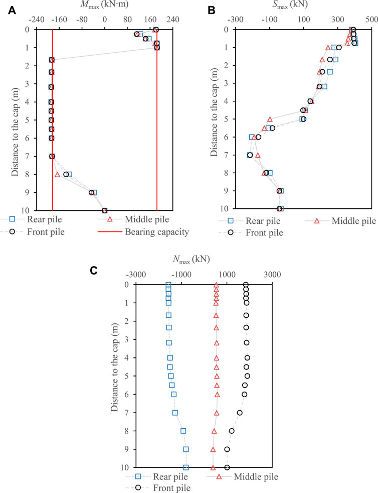
FIGURE 13. Distribution of the maximum internal force of a single pile at different rows (i.e., front, middle, and rear) (A) bending moment (Mmax), (B) shear force (Smax), and (C) axial force (Nmax) (Case 3).
5 Conclusion
A case study was carried out on the damage mechanism of the Nishikawa bridge abutment that was displaced riverwards due to soil liquefaction during 2011 Great East Japan earthquake. Some conclusions can be summarized from the numerical analyses:
(1) The shear failure of the bridge abutment was initialized from the inclined piles and then followed by the middle vertical pile. Thus, special treatments were necessary for inclined group piles in the engineering design to increase the shear capacity of the inclined pile.
(2) The earthquake—induced liquefaction caused substantial lateral displacement of soils around the piles and thus dominated the backward rotation of the abutments supported by inclined piles.
(3) The exclusion of the deck pinning effect may lead to a marked increase in the lateral displacement and rotation of abutments for simply supported beam bridges.
(4) The pile rake angle had insignificant effect on the lateral displacement of the abutment before the first peak horizontal acceleration was reached. However, after the arrival of the peak horizontal acceleration, a much larger lateral displacement was obtained for the abutment supported by vertical piles.
(5) The promotion of the Earth pressure behind the abutment was the main cause of the forward rotation of the abutment supported by vertical piles during earthquakes.
Data availability statement
The raw data supporting the conclusion of this article will be made available by the authors, without undue reservation.
Author contributions
Y-YX: Investigation, manuscript preparation, computation, revision; X-GW: Data curation; FC: Supervision, software.
Funding
This work was supported by Major Infrastructure Safety Guarantee Collaborative Innovation Special Funding Project of Jiangsu Province, China (Financial No. B210620221).
Conflict of interest
The authors declare that the research was conducted in the absence of any commercial or financial relationships that could be construed as a potential conflict of interest.
Publisher’s note
All claims expressed in this article are solely those of the authors and do not necessarily represent those of their affiliated organizations, or those of the publisher, the editors and the reviewers. Any product that may be evaluated in this article, or claim that may be made by its manufacturer, is not guaranteed or endorsed by the publisher.
References
Armstrong, R. J., Boulanger, R. W., and Beaty, M. H. (2013). Liquefaction effects on piled bridge abutments: Centrifuge tests and numerical analyses. J. geotechnical geoenvironmental Eng. 139 (3), 433–443. doi:10.1061/(asce)gt.1943-5606.0000780
Cai, F., Hagiwara, T., Imamura, S., and Ugai, K. (2002). “2D fully coupled liquefaction analysis of sand ground under tank,” in Proceedings of the 11th Japan earthquake engineering symposium, 819–824.
Cai, F. (2020). Effects of large-space latticed walls for liquefaction mitigation. J. X Univ. Nat. Sci. Ed. 39 (1), 1–11.
Cubrinovski, M., Haskell, J., Winkley, A., Robinson, K., and Wotherspoon, L. (2014). Performance of bridges in liquefied deposits during the 2010–2011 Christchurch, New Zealand, earthquakes. J. Perform. Constr. Facil. 28 (1), 24–39. doi:10.1061/(asce)cf.1943-5509.0000402
Forum 8 Co Ltd (2005). “Finite element fully coupled dynamic effective stress analysis program (UWLC),” in Electrical manual. Available at: https://www.forum8.co.jp/english/uc-1/uwlc.htm.
Gerolymos, N., Giannakou, A., Anastasopoulos, I., and Gazetas, G. (2008). Evidence of beneficial role of inclined piles: Observations and summary of numerical analyses. Bull. Earthq. Eng. 6 (4), 705–722. doi:10.1007/s10518-008-9085-2
Hardin, B. O., and Drnevich, V. P. (1972). Shear modulus and damping in soils: Design equations and curves. J. Soil Mech. Found. Div. 98 (7), 667–692. doi:10.1061/jsfeaq.0001760
Japan Road Association (JRA) (2004). Specifications for highway bridges-part V: Seismic design. 5th ed. Tokyo. [in Japanese].
Nakata, M., Tanimoto, S., Ohsumi, M., and Nanasawa, T. (2018). Large-scale shaking table test of existing abutment foundation in liquefiable ground. Civ. Eng. J. 60 (8), 40–43. [in Japanese].
National Institute for Land and Infrastructure Management of Japan (NILIM), Public Works Research Institute of Japan (PWRI) (2014). Reconnaissance report on damage to road bridges by the 2011 great east Japan earthquake.
Pastor, M., Zienkiewicz, O. C., and Chan, A. (1990). Generalized plasticity and the modelling of soil behaviour. J. Numer. Anal. methods geomechanics 14 (3), 151–190. doi:10.1002/nag.1610140302
Qu, C. X., Yi, T. H., Li, H. N., and Chen, B. (2018a). Closely spaced modes identification through modified frequency domain decomposition. Measurement 128, 388–392. doi:10.1016/j.measurement.2018.07.006
Qu, C. X., Yi, T. H., and Li, H. N. (2019). Mode identification by eigensystem realization algorithm through virtual frequency response function. Struct. Control Health Monit. 26, e2429. doi:10.1002/stc.2429
Qu, C. X., Yi, T. H., Zhou, Y. Z., Li, H. N., and Zhang, Y. F. (2018b). Frequency identification of practical bridges through higher order spectrum. J. Aerosp. Eng. 31, 04018018. doi:10.1061/(asce)as.1943-5525.0000840
SeismoSoft (2013). SeismoSignal version 4.3.0. Pavia, Italy: SeismoSoft ltd., inc. earthquake engineering software solutions, [online]2011 Available at: http://www.seismosoft.com.
Shin, H., Arduino, P., Kramer, S. L., and Mackie, K. (2008). Seismic response of a typical highway bridge in liquefiable soil. Geotechnical Earthq. Eng. soil Dyn. IV, 1–11.
Tanabe, A., Kouno, T., Nanazawa, T., and Tanimoto, S. (2016). Estimation of damage mechanism of bridges damaged by earthquakes. Civ. Eng. J. 58 (6), 38–41. [in Japanese].
Tazohb, T., Sato, M., Jang, J., and Gazetas, G. (2008). “Centrifuge tests on pile foundation-structure systems affected by liquefaction-induced soil flow after quay wall failure,” in The 14th world conference on earthquake engineering (Beijing, China.
Wakai, A., and Ugai, K. (2004). A simple constitutive model for the seismic analysis of slopes and its applications. Soils Found. 44 (4), 83–97. doi:10.3208/sandf.44.4_83
Wang, X. W., Ye, A. J., and Li, C. (2018). Seismic response of girder bridges in liquefiable river valleys with different structural configurations. J. Tongji Univ. Nat. Sci. 46 (6), 759–766.
Wang, Z., Dueñas-Osorio, L., and Padgett, J. E. (2013). Seismic response of a bridge–soil–foundation system under the combined effect of vertical and horizontal ground motions. Earthq. Eng. Struct. Dyn. 42 (4), 545–564. doi:10.1002/eqe.2226
Xu, L. Y., Cai, F., Wang, G. X., Ugai, K., Wakai, A., Yang, Q. Q., et al. (2013). Numerical assessment of liquefaction mitigation effects on residential houses: Case histories of the 2007 niigata chuetsu-offshore earthquake. Soil Dyn. Earthq. Eng. 53, 196–209. doi:10.1016/j.soildyn.2013.07.008
Xu, L. Y., Chen, W. Y., Cai, F., Song, Z., Pan, J. M., and Chen, G. X. (2023). Response of soil–pile–superstructure–quay wall system to lateral displacement under horizontal and vertical earthquake excitations. Bull. Earthq. Eng. 21 (2), 1173–1202. doi:10.1007/s10518-022-01572-z
Xu, L. Y., Song, C. X., Chen, W. Y., Cai, F., Li, Y. Y., and Chen, G. X. (2021). Liquefaction-induced settlement of the pile group under vertical and horizontal ground motions. Soil Dyn. Earthq. Eng. 144, 106709. doi:10.1016/j.soildyn.2021.106709
Keywords: abutment damage, inclined pile, u-p formulation, liquefaction, soil - pile - superstructure system
Citation: Xue Y-Y, Wang X-G and Cai F (2023) Effect of inclined pile on seismic response of bridge abutments undergoing liquefaction—Induced lateral displacement: Case study of Nishikawa bridge in the 2011 Great East Japan earthquake. Front. Mater. 10:1185210. doi: 10.3389/fmats.2023.1185210
Received: 13 March 2023; Accepted: 24 March 2023;
Published: 07 April 2023.
Edited by:
Chun-Xu Qu, Dalian University of Technology, ChinaReviewed by:
Hu Cheng, Jiangnan University, ChinaMingxin Li, Shandong University of Science and Technology, China
Copyright © 2023 Xue, Wang and Cai. This is an open-access article distributed under the terms of the Creative Commons Attribution License (CC BY). The use, distribution or reproduction in other forums is permitted, provided the original author(s) and the copyright owner(s) are credited and that the original publication in this journal is cited, in accordance with accepted academic practice. No use, distribution or reproduction is permitted which does not comply with these terms.
*Correspondence: Ying-Ying Xue, eHl5Mjg1MTA4QDE2My5jb20=