 Zai Liu1*
 Guoqing Chen
- 1Zhijian Laboratory, PLA Rocket Force University of Engineering, Xian, China
- 2Xi’an Aerospace Chemical Propulsion Co., Ltd., Xian, China
- 3School of Engineering and Architecture, Northeast Electric Power University, Jilin, China
- 4College of Architecture and Civil Engineering, Beijing University of Technology, Beijing, China
As one of the key components of solid rocket motors (SRMs) and launch vehicles (LVs), the deformation and damage of the composite rocket motor case (CRMC) can directly affect the effectiveness of the SRMs. Therefore, it is particularly important to analyze the damage failure of composite cases. As the analysis remains complex due to the different failure modes of composites at different scales, this paper applies multiscale analysis methods to CRMC damage. A multiscale mechanical model of CRMC is established, and data transfer between the microscale, mesoscale, and macroscale models is achieved using submodel techniques. In this paper, CRMC was finely modeled, and the thickness and carbon fiber angle of each fiber winding layer were accurately described. Additionally, the results of hydrostatic tests and numerical calculations were compared to verify the validity of the modeling method. The stress levels of the material at macroscale, mesoscale, and microscale scales were obtained through numerical calculations, and the microscale damage failure behavior of the material under the internal pressure load of the composite shell was predicted by combining the strength assessment criterion.
1 Introduction
Owing to the manufacturing process, CRMCs are often designed for refinement with possible failures in the dome or some critical areas (Özaslan et al., 2022; Srivastava et al., 2022a; Wu et al., 2022). This is highly detrimental to the overall safety of the SRM. Furthermore, considering the complex working conditions during the use of CRMCs, such as pressure curing and reuse, there is also potential damage to CRMCs (Nebe et al., 2021; Wang et al., 2022). This makes it imperative to understand the safety of CRMCs. This creates an urgent need to understand the microscale damage characteristics of CRMCs and to reliably assess their structural integrity and safety. Therefore, multiscale refinement modeling of CRMCs is of particular importance and is currently a research priority in the field of SRMs.
CRMCs are usually made using wet fiber winding technology with T700 carbon fibers and an epoxy resin reinforced system, offering a light weight, high strength, and fatigue resistance superior to conventional metals (Srivastava et al., 2022b; Meyer et al., 2022; Zhang et al., 2022). Existing studies have shown that the physical and mechanical properties and overall reliability of CMRCs are influenced by the thickness of the fiber winding layer, the fiber winding angle, the lay-up sequence, and the fiber winding process (Park and Sakai, 2020; Zaami et al., 2020; Zu et al., 2020; Hu et al., 2021; Błachut et al., 2023). (Özaslan et al. (2018) investigated the effect of the variation of fiber volume fraction due to fiber winding thickness and the manufacturing process on the mechanical properties of pressure vessels through numerical simulations and experiments; Nguyen et al. (2021) investigated the effect of spiral ply winding angle on the damage evolution and rupture pressure of composite vessels and found that appropriate fiber orientation could significantly reduce early matrix cracking; Nebe et al. (2020) analyzed the effect of lay-up sequence (high-angle and low-angle plies) on the lay-up quality, structural surface deformation, and final burst pressure of composite pressure vessels. The results showed that the final burst pressure of composite vessels with different lay-up sequences could vary by 67%. The parameters of fiber tension and their associated challenges are discussed based on numerical simulations, and the manufacturing process of fiber tension is explored, showing that an increase in fiber tension causes compressive stresses that lead to an increase in burst pressure (Błachut et al., 2023). Liu and Shi (2020) proposed an optimization model for obtaining a better load-bearing capacity of the composite vessel and achieving the optimum fiber winding angle and tension based on the fiber winding process and curing residual stresses.
Therefore, reasonable control of key parameters in the CRMC fabrication process can further optimize the overall force performance of the structure and improve the overall effectiveness of the SRM. However, it is very time consuming and uneconomical to rely solely on experiments to verify the optimal design parameters of CRMCs under different test conditions. Moreover, the experiments can only observe the macroscale damage results on the surface of the CRMC and cannot accurately characterize the microscale damage characteristics of the critical parts of the structure during the tests. By contrast, finite element analysis (FEA) methods have been used to study the mechanical properties, damage processes, and optimal design of composite structures due to their powerful design capabilities and reliable simulation (Dahl et al., 2019; Ebermann et al., 2022; Solazzi and Vaccari, 2022).
Wang et al. (2015) predicted the burst strength and complex damage behavior of aluminum-carbon fiber/epoxy composite vessels based on a progressive damage model and found that the main forms of failure for the ring-wound and spiral-wound layers were fiber fracture and matrix cracking, respectively, and that delamination failure between the outer composite layers was more severe. Considering the debonding of the composite/liner layers and the variation of fiber thickness and angle in the dome section, Ahmadi Jebeli and Heidari-Rarani, (2022) modeled a type IV composite pressure vessel using the Wound Composite Modeler (WCM) plug-in in Abaqus to simulate the debonding process of the composite case from the liner and tab during curing, and found that the initial debonding did not affect the progressive damage process of the cylinder composite plies. However, direct modeling of the microstructure of carbon-fiber-reinforced polymers (CFRP) using previous finite element methods is too complex and difficult to handle. Moreover, detailed microstructure geometry modeling requires fine mesh cells and huge computational costs (Zhai et al., 2022). Multiscale models linking microscale to macroscale composite layers have been successfully used for the evaluation and analysis of CFRPs.
J. Aboudi (1989) first proposed the concept of method of cells (MOC) in 1989. MOC divides the representative volume element (RVE) in fiber-reinforced composite materials into four sub cells, with one sub cell representing the fiber and the other three sub cells representing the matrix. By analyzing this type of RVE, the known material properties of fibers and matrices can be used to predict the overall performance of different types of composite materials. Paley and Aboudi (1992) promoted MOC to generalized method of cells (GMC) in 1992. GMC can be applied to fiber-reinforced, metal matrix, and woven polymer matrix composites (Pahr and Arnold, 2002). In GMC, macroscopic behavior can be well determined, but due to linear displacement expansion and a lack of shear coupling effects, local fields of strain and stress cannot be well captured (J. Aboudi, 2004). J. Aboudi et al. (2002) established a high-fidelity generalized method of cells (HFGMC) based on GMC. By utilizing the quadratic polynomial expansion of the displacement field, the HFGMC is introduced to solve this problem. Liu et al. (2012) proposed a multiscale damage model to predict the damage characteristics and ultimate burst pressure of composite pressure vessels, and described the macroscale damage evolution and stiffness properties of CFRPs using representative volume units (RVE). Lin et al. (2021) introduced RVE to calculate the degradation elastic parameters of the composite (including fiber and matrix damage modes) using the finite element method and simulated the multiscale progressive damage of the composite plies during the hydraulic impact test. The results show that the microscale finite element model can effectively predict the progressive damage of composite pressure vessels under internal pressure, such as matrix cracking, interlaminar damage, and fiber fracture.
The delamination failure and failure mechanism of composite materials at the mesoscale require an appropriate model to accurately evaluate their mechanical research. Carrera (2003) explained theoretically that owing to lateral anisotropy and the difference between the transverse shear and normal modulus of the layer, there is a phenomenon of slope discontinuity in the displacement field, which is called the ZigZag (ZZ) phenomenon. Tessler et al. (2007) developed the refined zigzag theory (RZT) based on zigzag models (ZZ), which allows continuous interpolation of all kinematic variables. It has the characteristic of disappearing on the top and bottom surfaces of the laminate. Tessler et al. (2007) was used to solve the static bending problem of soft core sandwich composite beams using ZZ; Malekimoghadam et al. (2023) used the RZT to study the bending analysis of sandwich and laminated carbon-nanotube-coated fiber multiscale composite beams. However, RZT cannot predict the macroscopic cracking failure of the interface layer. In recent years, cohesive zone models (CZM) have been widely used in finite element analysis to predict the interface failure behavior of composite laminates (Bruno et al., 2005; Gliszczynski and Wiącek, 2021; Linke and Lammering, 2023b). Linke and Lammering (2023a) used CZM to accurately calculate the initiation and subsequent propagation of cracks at the microscale in a finite element model, taking into account local progressive material degradation, to explain non-linear fracture behavior. In this study, finite element analysis was used to predict the interface failure behavior of composite laminates.
Srivastava et al. (2022b) connected the microscale, mesoscale, and macroscale models and used RVE with periodic boundary conditions to establish a multiscale mechanical model of CFRPs and calculated the homogenized modulus of elasticity and Poisson’s ratio for the whole structure, and the numerical calculation results were in general agreement with the experimental data. However, to the authors’ knowledge most of the current research on CFRPs has only explored one direction in the fiber lay-up process, macroscale failure behavior, and fine structure damage, and has not combined the fiber winding and lay-up process to provide a full chain integrity analysis of CRMCs from macroscale strength to fine structure. This is sorely lacking in the current SRM field.
In this study, a multiscale numerical model of CRMCs was established to simulate the multiscale damage failure of CRMCs. First, the geometric modeling of the refined solid rocket motor shell was established through Abaqus WCM, and the macro finite element model was generated based on the geometric modeling. CZM was introduced into the meso finite element model to characterize the interlaminar failure behavior of composite materials, and the stress distribution level and damage failure of the meso model were characterized through the RVE model.
The main contribution of this study is the multiscale refinement modeling of the macroscale structure of CRMCs and the realization of the interactive simulation analysis from the design end to the fine view end. This study provides theoretical guidance for the safe and economic design and practical application of CRMCs in the field of SRM at presentation, physical exams, and lab results.
2 Materials and methods
2.1 Finite element model of CRMCs
The geometric modeling of CRMCs is based on the theory of wound carbon fiber case modeling and the WCM modeling module of Abaqus. Three kinds of finite element models at macroscale, mesoscale, and microscale scales were established; at the same time, to investigate the debonding behavior between the wound layers, cohesive elements were embedded in the mesoscale model to characterize the interfacial layers.
2.1.1 Geometric modeling of CRMCs
Figure 1A shows the winding device of the CRMC. CRMCs are wound alternately in a circular direction (the winding angle is close to 90° but less than 90°) and in a spiral direction (a winding angle between 12 and 70°). The winding process is as follows: the fibers start from a certain point on the circumference of the pole hole at one end of the container; follow the curve tangent to the pole hole circle on the surface of the dome and wind around the dome; follow the spiral line track around the cylinder section and enter the dome at the other end; then return to the cylinder section and finally wind back to the dome and so on, until the surface of the core mold is evenly covered with fibers.
FIGURE 1. CRMC molding method and Geometry model for CRMC. (A) Winding device of the CRMC; (B) Geometry for CRMC; (C) Schematic diagram of the different fiber orientations in CRMC.
Owing to the characteristics of spiral winding, the angle of carbon fiber winding at the dome and the accumulated thickness of the winding layer will change, which can be expressed by Eq. 1.
The winding angle along the case ring remains the same. The spiral winding angle at the dome is:
For the spiral layer in the dome section, the layer thickness gradually increases near the pole hole and then rises sharply, with the cumulative thickness expressed by Eq. 2 as follows:
where R and R0 are the radial distances from the central axis of the housing to the specified point in the layer and the end of the wound layer near the pole hole. Rtl is the radial distance from the central axis to the wound layer at ttl, θtl are the winding angles for the thickness of the winding layer, θr is the winding angle at the specified point, and BW is the bandwidth. Based on the above theory, the thickness of the circumferential and spiral winding layer is entered in the WCM plug-in as 1 mm, the thickness of the reinforcing carbon fiber fabric is 0.5 mm, the circumferential winding angle is 27°, and the winding termination type is rounded. The specific CRMC molding process parameters and the winding setup with the reinforcing layer are shown in Table 1. The resulting case geometry model is shown in Figure 1B. Figure 1C shows a schematic diagram of the different fiber orientations in the CRMC.
TABLE 1. Structural design results of the CRMCs.
2.1.2 Macroscale finite element model
The refined geometric model is meshed, and the macroscale finite element model should take into account the thickness of the winding layers and the winding angle information. The characteristic line information of the winding layer of the geometric model is retained in the mesh division, and each layer of the winding layer is divided into one mesh. The macroscale scale mesh model also needs to control a parameter called the winding angle increment. The winding angle increment is a grouping of winding angles, with the winding angle of each winding layer varying over the winding layers. Thus, each cell can theoretically have its own winding angle. To reduce the calculation time, the cells are grouped together according to the winding angle increments. For example, cells with a winding angle between 10 and 10.5° can be grouped into a “layer” and the material properties of all cells in that layer are generated. As the winding angle of the cylinder remains constant, each winding angle in these areas contains many cells. Owing to the rapid change in winding angle at the dome, the winding layers closer to the pole hole will contain a smaller number of cells.
Figure 2 shows the macroscale mesh model. To improve the efficiency of the calculation, the full model 1/4 is used, in which the metal joints, rubber insulation, and fiber winding layer are all in C3D8R cells (eight-node linear hexahedral cells with reduced integration and hourglass control). The number of elements for the entire macroscale finite element model is 384,000.
FIGURE 2. Finite element model for composite case.
2.1.3 Mesoscale finite element model
The mesoscale finite element model is a local area mesh model intercepted from the macroscale model and embedded with cohesive elements between the winding layers. In this study, the nodal displacements calculated in the macroscale model are mapped to the submodel boundaries using the mapped displacements as boundary conditions for the mesoscale model analysis, and then the mechanical behavior of the interface layers between the winding layers is simulated, such as debonding due to damage of the interface layers. Owing to the different stress states of the carbon fiber winding layers at different locations on the case when subjected to internal pressure loading, the location where damage occurs on the case during internal pressure was selected as the selection point based on the results of the macroscale finite element analysis. Figure 3 shows the mesoscale submodel.
FIGURE 3. Multi-scale finite element model of CRMCs.
2.1.4 Microscale finite element model
For some micromechanical analysis models, fibers in the microscale submodel are traditionally assumed to be periodically aligned. However, a microscale submodel with randomly distributed fibers should better characterize the non-uniform dispersion of fibers in composites when modeling local damage behavior, such as matrix fracture. To this end, we used the random sequence expansion (RSE) algorithm (Yang et al., 2013) that obtains the random distribution of fibers with high volume fractions, and the algorithm satisfies the spatial statistical evaluation criteria well at high volume fraction fibers.
In this study, the microscale submodel is divided into three parts: fiber bundle, matrix and interfacial layer, and the fiber volume fraction considered is approximately 60%. According to the recommendation by Trias et al. (2006), the fiber diameter was set to 4.5 µm and the interfacial thickness was set to 0.01 µm. To investigate the transverse and fiber-oriented behavior of unidirectional fiber/polymer composites, three-dimensional scale model simulation conditions are used in this paper. The fiber and matrix are mainly associated with eight-node linear hexahedral cells, reduced integral cells are used for computational efficiency, simplified integral elements (C3D8R) are meshed, and nodal linear plane strain triangular elements (C3D6R) are also involved. According to the 0.01 µm thickness used in the literature (Yuan et al., 2023), the actual modeling in this paper uses a zero-thickness cell with an equivalent thickness of 0.01 µm. Figure 3 shows a typical microscale submodel with a magnified image clearly showing the fiber bundle, the matrix, and the interface layer. To ensure both suitable numerical accuracy and computational efficiency, a grid size of 2 µm was used. The grid size of the entire area except for the interface is meshed, so that the microscale submodel consists of approximately 20,000 elements.
2.1.5 Material properties
The composite layer of the case can be regarded as a single-layer plate, and according to the law of shear stress equivalence, the unit body in the single-layer plate is defined by the tensor shear strain, with six components of stress and strain each. The relationship between stress and strain is established through the stiffness coefficient matrix and expressed as:
According to the fact that the strain energy density differential of the elastic element is independent of the subscript order, when the element is deformed into linear elasticity, the stiffness coefficient is reduced to 21 independent stiffness coefficients in the stiffness coefficient matrix. In fact, the vast majority of materials have symmetrical internal structures, thus they have elastic symmetry. If the material has two orthogonal elastic symmetry planes, it is called an orthotropic material. According to the orthotropic properties, the strain energy density, including the elastic symmetry plane, should be zero to ensure that the strain energy density function remains unchanged. At this time, the material has only nine independent stiffness coefficients, so the constitutive equation of orthotropic material is:
The vertical and circularly wound carbon fibers are made of T700 and the reinforcement layer is made of T300. The mechanical properties parameters of T700/T300 are shown in Table 2. The front and rear skirts and the front and rear joints, which are non-critical areas, are treated as a linearly elastic nature of aluminum and rubber. The mechanical properties parameters of aluminum measured by a tensile tester are shown in Table 3.
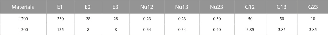
TABLE 2. Elastic constants of T700/T300 (GPa) (Lin et al., 2021).

TABLE 3. Elastic constants of aluminum/rubber.
2.2 Failure model
2.2.1 Macroscale failure model
LaRC05 is used as a failure criterion for the macroscale dimensions of composite cases, dividing the composite failure modes into matrix failure, fiber compression failure, and fiber tension failure. Transverse compression non-linearity, fiber bending failure, in situ effects, and pressure dependence are fully considered. LaRC05 expresses the pressure dependence of composites in terms of the growth of the modulus of elasticity and shear modulus with external pressure under hydrostatic pressure (pressure dependence) as a linear relationship. This relationship is expressed as
where
2.2.1.1 LaRC05 matrix failure criterion
LaRC05 uses a uniform expression to describe the failure of the matrix, which is given by
where σn ≥ 0 if the matrix fails in tension and σn ≤ 0 when the matrix fails in compression. When FIM ≥1, structural failure is determined. ⟨σN⟩ = (σN + |σN|)/2 is the in situ strength formula.
2.2.1.2 LaRC05 fiber tensile failure criterion
The LaRC05 fiber tensile failure criterion uses the maximum stress criterion:
where XT is the longitudinal tensile strength when FIT ≥ 1 failure is determined.
2.2.1.3 LaRC05 fiber compression failure criterion
The LaRC05 fiber compression failure model uses a fiber bending model and uses the same equation to describe fiber bending damage and splitting damage:
Based on the mode of application of axial compressive loads to the composite, LaRC05 classifies fiber longitudinal compression failures when σ11 ≤ −Xc/2 bending failure mode and σ11 ≥ −Xc/2 when the fiber is bent and when the fiber is broken. Table 4 shows the parameters to be defined for the macroscale failure criterion.
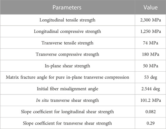
TABLE 4. Parameters of the LARC05 criterion (Zu et al., 2020).
2.2.2 Microscale failure model
The carbon fiber filament damage initiation criterion is as follows:
where
The matrix damage initiation criterion is as follows:
where Tm is the tensile strength of the substrate and Cm is the compressive strength of the substrate.
The parameters of the LARC05 criterion are shown in Table 4.
2.2.3 Interface layer failure model
The interface material between the wound layers is the binder, and the actual observation of its interface thickness is very thin, making it difficult to model the dimensions to simulate the mechanical behavior of the interface, and this study simulates its failure behavior through its cohesion unit. A bonding unit is introduced at each interface of the adjacent layers in the composite model. A stress damage criterion for estimating the damage onset time is given as:
where σi are the traction stress vectors in the normal and shear directions and N, S, and T are defined as the corresponding interlaminar normal and two shear strengths. The cohesion unit generally uses a bilinear traction-separation response intrinsic relationship to model the process of delamination damage sprouting and extension, as shown in Figure 4 ti is the cohesive element traction stress and δi is the separation displacement in three directions.
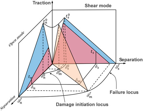
FIGURE 4. Bilinear mixed-mode traction-separation law.
Once damage (in the form of cracks) has started, the stiffness of the bonded unit gradually degrades in the form of a damage variable d, which ranges from zero at the start of damage to one at the complete destruction of the interface unit. The mixed-mode loading with energy release rates with modes I, II, and III is used to predict damage growth.
The energy-based damage evolution criterion is defined by the following equation (Eq. 14).
where Gc is the critical fracture energy in each direction at the interface (J/m2) and β is the energy-based damage evolution index.
For a linear softening process, the evolutionary damage variable d is defined as:
where
The parameters of the mechanical property of cohesive law are shown in Table 5.
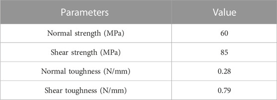
TABLE 5. Mechanical properties of cohesive law (Ahmadi Jebeli and Heidari-Rarani, 2022).
2.3 Experimental verification of the simulation model
2.3.1 Experimental program
The distribution of strain gauge is shown in Figures 5A, B. Three sets of strain gauge are arranged at the cylinder, and three sets of strain gauge are also arranged at the front and rear domes. Each group is arranged with one strain gauge parallel to the fiber direction and one strain gauge perpendicular to the fiber direction. In addition, one temperature compensation plate is set in the environment where the engine casing is located. The model of strain gauge is BMB120-10AA-P5000-D, the resistance value is 120.0 ± 0.3 Ω, the current value is 1 mA, and the sensitivity coefficient is 2.0% ± 1%.
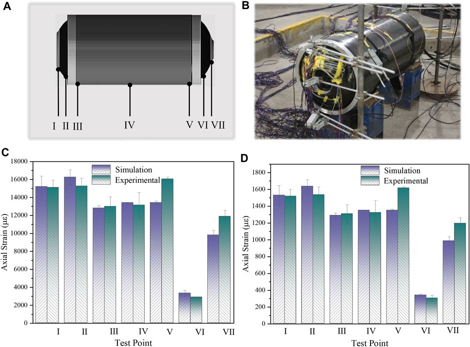
FIGURE 5. Strain testing and comparison of experimental and simulation results under internal pressure of 3MPa and 30 MPa in the case. (A) Test points for strain monitoring; (B) Strain sensor and wire layout diagram; (C) Comparison of experimental and simulation results under internal pressure of 3 MPa; (D) Comparison of experimental and simulation results under internal pressure of 30 MPa.
When collecting shell strain, considering the rapid strain changes during the pressurization and depressurization stages, the collection frequency of all channels is 5 Hz. When collecting shell temperature, the collection frequency of all channels is 0.1 Hz. The procedure for conducting internal pressure tests on the composite casing of a solid rocket motor is as follows: 1) Sealing test of the test object; inject water into the casing and install a pressure sensor, then pressurize the water to 1 MPa and stabilize the pressure for 30–50 s. Observe the stability of water pressure through sensors. 2) Strain measurement: for the convenience of strain collection, the hydraulic graded loading method is adopted, with each pressure increase step of 1 MPa and the pressure increasing from 1 MPa to 18 MPa. If there is no damage to the shell under an internal pressure of 18 Mpa, adjust the pressure increase step to 0.5 MPa. Measure the strain at monitoring points under different internal pressures.
2.3.2 Experimental verification
To avoid the influence of discrete data on the comparison results, data readings were taken for three adjacent units at each monitoring point location in the simulation analysis results, and strain results were also counted separately for the three internal pressure experiments. Figures 5C, D shows the comparison curves of the case axial strain experiments and results at an internal pressure of 3 MPa and 30 MPa. The comparison curve shows that the numerical calculations and test results for test points I, II, III, IV, V, VI, and VII have a good correlation, with the ratio of the difference between the two being less than 20%.
3 Results and discussion
3.1 Macroscale simulation results
Based on the finite element model developed by Abaqus, a progressive damage analysis of the composite pressure vessel was carried out using a subroutine obtained from the LaRc05 failure criterion.
Figure 6A shows the circumferential strain curve of the case in axial coordinates under internal pressures of 10 MPa, 30 MPa, and 50 MPa. The best method to predict the location where the CRMC is prone to failure is to apply a pressure of 0–50 MPa to the shell and observe the magnitude and distribution of circumferential strain values. When the shell is subjected to internal pressure, the maximum circumferential strain of the composite layer occurs at the cylinder. When the pressure is 50 MPa, the maximum circumferential strain is 0.024. Figure 6B shows the maximum circumferential strain curve of the case under different internal pressures. The curve shows that the maximum circumferential strain increases linearly with increasing pressure, which is due to the fact that the fiber are brittle materials. There is good consistency between the experimental and numerical results of the maximum circumferential strain in Figure 6B. Figures 6A, B shows the circumferential strain is highest in the transition zone between the head and the cylinder, which is consistent with the experimental and simulation results of the study (Nebe et al., 2021).
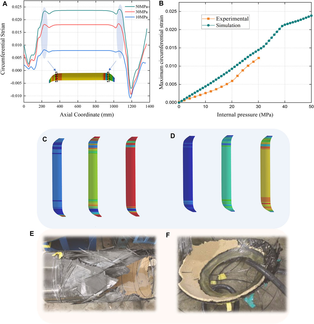
FIGURE 6. Macro-scale finite element analysis results. (A) Circumferential strain curve of the case in axial coordinates under internal pressures of 10 MPa, 30 MPa, and 50 MPa; (B) Maximum circumferential strain curve of case under different internal pressures; (C) Simulation results of case matrix damage under internal pressures of 10 MPa, 30 MPa, and 50 MPa; (D) Simulation results of case fiber damage under internal pressures of 10 MPa, 30 MPa, and 50 MPa; (E) Failure diagram of the shell under internal pressure-cylinder section; (F) Failure diagram of the shell under internal pressure-cylindrical case section- Dome.
The simulation results of the case matrix and fiber damage under internal pressures of 10 MPa, 30 MPa, and 50 MPa are shown in Figures 6C, D. Under an internal pressure of 10 MPa, the failure of the Matrix occurs near the pole hole and the circumferential winding of the cylinder, which is caused by the lower strength of the circumferential winding layer near the pole hole and the circumferential winding layer in the cylinder, i.e., the lower strength in the vertical fiber direction. As the internal pressure increased to 30 MPa, the matrix failure at the dome gradually evolved towards the cylinder, and damage occurred to the spiral-wound layer in the cylinder. As the internal pressure increased to 50 MPa, the case expanded outwards and severe matrix tensile failure occurred across the entire column surface. No fiber damage was found at internal pressures of 10 MPa. As the internal pressure increased to 30 MPa, damage was observed in the middle of the dome and in the transition area between the dome and the cylinder, and as the internal pressure increased to 50 MPa, the transition area of the cylinder exhibited fiber fracture due to the large tensile forces generated by the composite layer. In addition, fiber damage occurred first in the spiral-wound layer of the cylinder, and no fiber failure under compression and flexural failure were found; therefore, fibers play an important load-bearing role under internal pressure, and when many fiber breaks occur in the composite layer, the composite pressure vessel will lose its ability to withstand the internal pressure.
When the test pressure in the case is 30.0 MPa, the case ruptures from the cylinder segment. The disintegration of the fiber winding case is the two parts shown in Figures 6E, F, the degree of failure of the dome and cylinder section is basically the same, the case realizes equal strength design, combined with the failure of the case, it can be inferred that the first failure position in the blasting process is the transition zone of the case dome and the barrel segment, and then the cylinder segment is torn, which is consistent with the numerical simulation of the result of greater strain in the transition zone of the case dome and the barrel segment.
However, the analysis of macroscale stress-strain results alone does not provide an accurate and intuitive picture of the damage characteristics and damage mechanisms of solid engine casings. For this reason, further damage failure analysis is required at the point of maximum strain based on the mesoscale model and microscale model.
3.2 Mesoscale simulation results
To better observe the failure behavior between the winding layers, the finite element model used for mesoscale calculations has embedded cohesive elements between each winding layer, while submodel techniques are applied to map the results of macroscale nodal displacement calculations into the mesoscale model, which can simulate the failure behavior between the winding layers. The displacement results from the mesoscale numerical simulations will be used as input boundaries for the microscale numerical simulations.
According to the macroscale calculation results, the matrix damage and fiber damage states are different at different locations of the composite case; therefore, to capture the most vulnerable situation of the case, seven locations, as shown in Figure 7B, were selected as the mesoscale numerical simulation area. Figure 7A is a schematic diagram of the structure of the mesoscale model.
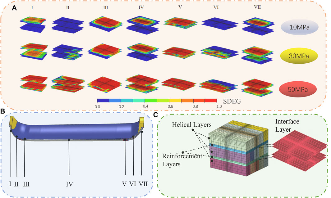
FIGURE 7. Mesoscale finite element analysis results. (A) Interface layer damage at different locations; (B) Selected mesoscale model simulation area schematics; (C) Mesoscale model.
Figure 7A shows the damage clouds for the interlaminar cohesive element in the mesoscale models at different locations for internal pressure loads of 10 MPa, 30 MPa, and 50 MPa, considering a damage value of zero as no damage found and 0.99 as failure occurring between the layers. In all mesoscale models, the interlaminar damage value increases with the internal pressure load and the damage area increases with the internal pressure load. At the selected locations I, III, IV, V, IV, the first interlayer damage occurred at an internal pressure of 10 MPa. With the increase of load to 30 MPa, the interlayer damage at positions I, III, IV, V and IV gradually expands from the outside to the inside. Finally, the pressure is increased to 50 MPa. Since the load exceeds the bearing capacity of the interface layer, all the interface layers are damaged, and the damage value reaches the maximum value of 0.99.
For models II and VI, no interlaminar damage occurs at an internal pressure of 10 MPa, and the area of interlaminar damage at an internal pressure of 30 MPa is also significantly smaller than other locations. Additionally, the influence of the interlaminar shear effect in the middle of the dome leads to the phenomenon of chunking in the damage area.
3.3 Microscale simulation results
In the Abaqus simulation, the Mohr strength criterion was written, and the maximum strain damage initiation criterion user subroutine was used to perform damage analysis on the composite case at the microscale. Figure 8A shows the results of the microscale model matrix damage analysis with model numbers distributed as I, II, III, IV, V, VI, and VII. Under 10 MPa of pressure, models I, III, IV, V, VI, and VII all showed a small amount of matrix failure and model II did not show damage failure. Under 30 MPa of pressure, models I and VII showed a large continuous area failure phenomenon, while models III, IV, and V showed a discrete distribution of failure, and model II failed in a small area near the fibers. Under 50 MPa of pressure, models I, II, and III failed in a small area near the fibers. Under 50 MPa of pressure, models I, II, III, IV, V, VI, and VII all showed large area failures. It is noteworthy that the failure areas of different models are different. This is because of the fact that the fiber direction of models I and VII at the dome near the pole hole is close to 0°, and the axial strain here is larger than the circumferential strain. When the model is subjected to tensile forces perpendicular to the fiber direction, the matrix is the main load-bearing material, and due to the low strength of the matrix, a large continuous area of failure occurs; the failure areas of models II and VI at the middle of the dome are crossed. This is because of the fact that the model is affected by the shear strain, while models III, IV, and V in the transition zone of the dome and barrel and the cylinder are mainly subjected to tension in the parallel fiber direction and thus failures occur in a discrete distribution in the vertical fiber plane.
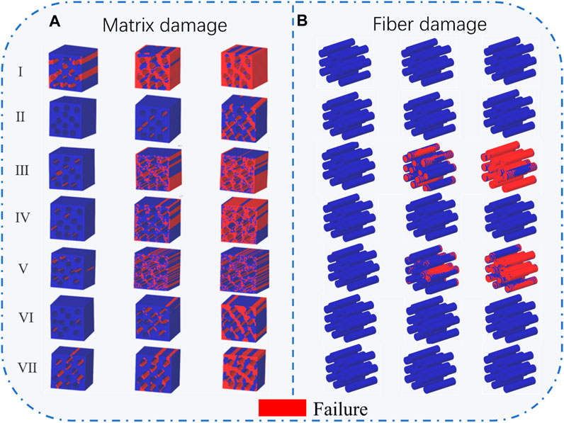
FIGURE 8. Microscale finite element analysis results. (A) Matrix damage; (B) Fiber damage.
Figure 8B shows the results of the microscale model fiber damage analysis. The results revealed that only the transition region of the dome and cylinder, corresponding to Models II and IV, experienced fiber fracture failure. The fiber damage at internal pressures of 10 MPa, 30 MPa, and 50 MPa was examined. At an operating internal pressure of 10 MPa, no fiber bundle failure was observed, while at 30 MPa, the fiber bundles already showed localized failure, and at an operating internal pressure of 50 MPa, all fibers in the model failed.
4 Conclusion
Based on the CRMC winding process scheme, refined modeling and strength calculations were obtained for the CRMC. The macroscale, mesoscale, and microscale damages of the CRMC under different internal pressure loads were investigated, and a multiscale method was developed to carry out the CRMC safety analysis. The following conclusions were obtained.
• The results of the numerical simulation of the macroscale model at an internal pressure of 3 MPa and the test axial strain were compared. The accuracy of the simulation results can reach more than 80% without considering the influence of local effects at fixed positions, which verifies the finiteness of the model and provides the basic conditions for multiscale analysis.
• Through macroscale analysis, it was found that with the increase of internal pressure, composite pressure vessels commonly fail in the matrix first and finally expand into fiber fractures, while also deriving the location of matrix and fiber damage failure of the case under different internal pressure loads, identifying the danger points and providing a basis for the selection of submodel analysis areas.
• The interlaminar failure mode, matrix failure, and fiber fracture failure were different at different locations in the case by mesoscale and microscale analyses. At an internal pressure load of 10 MPa, matrix failure and interlaminar damage occurred first in the case cylinder, at the pole hole and in the transition area of the dome and cylinder. However, when the internal pressure load reached 30 MPa, the area of matrix and interlaminar damage expanded and local fiber failure occurred in the transition area of the dome and cylinders. Additionally, all fibers in the transition zone of the cylinder failed under 30 MPa of internal pressure.
Data availability statement
The raw data supporting the conclusion of this article will be made available by the authors, without undue reservation.
Author contributions
ZL contributed to conceptualization, methodology, investigation, and original draft writing. GC was responsible for writing—review and editing and data curation. WH performed methodology, validation, formal analysis, and data curation. PC contributed to project administration and methodology. All authors contributed to the article and approved the submitted version.
Funding
This work was financially supported by the National Natural Science Foundation of China (51769028, 51508137).
Conflict of interest
Author WH was employed by Xi’an Aerospace Chemical Propulsion Co., Ltd.
The remaining authors declare that the research was conducted in the absence of any commercial or financial relationships that could be construed as a potential conflict of interest.
Publisher’s note
All claims expressed in this article are solely those of the authors and do not necessarily represent those of their affiliated organizations, or those of the publisher, the editors and the reviewers. Any product that may be evaluated in this article, or claim that may be made by its manufacturer, is not guaranteed or endorsed by the publisher.
References
Ahmadi Jebeli, M., and Heidari-Rarani, M. (2022). Development of Abaqus WCM plugin for progressive failure analysis of type IV composite pressure vessels based on Puck failure criterion. Eng. Fail. Anal. 131, 105851. doi:10.1016/j.engfailanal.2021.105851
Błachut, A., Wollmann, T., Panek, M., Vater, M., Kaleta, J., Detyna, J., et al. (2023). Influence of fiber tension during filament winding on the mechanical properties of composite pressure vessels. Compos. Struct. 304, 116337. doi:10.1016/j.compstruct.2022.116337
Bruno, D., Greco, F., and Lonetti, P. (2005). Computation of energy release rate and mode separation in delaminated composite plates by using plate and interface variables. Mech. Adv. Mater. Struct. 12, 285–304. doi:10.1080/15376490590953563
Carrera, E. (2003). Historical review of Zig-Zag theories for multilayered plates and shells. Appl. Mech. Rev. 56, 287–308. doi:10.1115/1.1557614
Dahl, E., Becker, J. S., Mittelstedt, C., and Schürmann, H. (2019). A new concept for a modular composite pressure vessel design. Compos. Part Appl. Sci. Manuf. 124, 105475. doi:10.1016/j.compositesa.2019.105475
Ebermann, M., Bogenfeld, R., Kreikemeier, J., and Glüge, R. (2022). Analytical and numerical approach to determine effective diffusion coefficients for composite pressure vessels. Compos. Struct. 291, 115616. doi:10.1016/j.compstruct.2022.115616
Gliszczynski, A., and Wiącek, N. (2021). Experimental and numerical benchmark study of mode II interlaminar fracture toughness of unidirectional GFRP laminates under shear loading using the end-notched flexure (ENF) test. Compos. Struct. 258, 113190. doi:10.1016/j.compstruct.2020.113190
Hu, Z., Chen, M., Zu, L., Jia, X., Shen, A., Yang, Q., et al. (2021). Investigation on failure behaviors of 70 MPa Type IV carbon fiber overwound hydrogen storage vessels. Compos. Struct. 259, 113387. doi:10.1016/j.compstruct.2020.113387
J Aboudi, J. (1989). Micromechanical analysis of composites by the method of cells. Appl. Mech. Rev. 42, 193–221. doi:10.1115/1.3152428
J Aboudi, J., Pindera, M.-J., and Arnold, S. M. (2002). High-fidelity generalization method of cells for inelastic periodic multiphase materials.
J Aboudi, J. (2004). The generalized method of cells and high-fidelity generalized method of cells micromechanical models—a review. Mech. Adv. Mater. Struct. 11, 329–366. doi:10.1080/15376490490451543
Lin, S., Yang, L., Xu, H., Jia, X., Yang, X., and Zu, L. (2021). Progressive damage analysis for multiscale modelling of composite pressure vessels based on Puck failure criterion. Compos. Struct. 255, 113046. doi:10.1016/j.compstruct.2020.113046
Linke, M., and Lammering, R. (2023a). On the calibration of the cohesive strength for cohesive zone models in finite element analyses. Theor. Appl. Fract. Mech. 124, 103733. doi:10.1016/j.tafmec.2022.103733
Linke, M., and Lammering, R. (2023b). “On the numerical modeling of interlaminar sensors in a composite stiffener: Optimization under fracture mechanical aspects,” in European workshop on structural health monitoring. Editors P. Rizzo, and A. Milazzo (Cham: Springer International Publishing), 764–773.
Liu, C., and Shi, Y. (2020). Design optimization for filament wound cylindrical composite internal pressure vessels considering process-induced residual stresses. Compos. Struct. 235, 111755. doi:10.1016/j.compstruct.2019.111755
Liu, P. F., Chu, J. K., Hou, S. J., and Zheng, J. Y. (2012). Micromechanical damage modeling and multiscale progressive failure analysis of composite pressure vessel. Comput. Mater. Sci. 60, 137–148. doi:10.1016/j.commatsci.2012.03.015
Malekimoghadam, R., Hosseini, S. A., and Icardi, U. (2023). Bending analysis of carbon nanotube coated–fiber multi-scale composite beams using the refined zigzag theory. Aerosp. Sci. Technol. 138, 108328. doi:10.1016/j.ast.2023.108328
Meyer, C. S., Catugas, I. G., Gillespie, J. W., and Gama Haque, B. Z. (2022). Investigation of normal, lateral, and oblique impact of microscale projectiles into unidirectional glass/epoxy composites. Def. Technol. 18, 1960–1978. doi:10.1016/j.dt.2021.08.012
Nebe, M., Asijee, T. J., Braun, C., van Campen, J. M. J. F., and Walther, F. (2020). Experimental and analytical analysis on the stacking sequence of composite pressure vessels. Compos. Struct. 247, 112429. doi:10.1016/j.compstruct.2020.112429
Nebe, M., Soriano, A., Braun, C., Middendorf, P., and Walther, F. (2021). Analysis on the mechanical response of composite pressure vessels during internal pressure loading: FE modeling and experimental correlation. Compos. Part B Eng. 212, 108550. doi:10.1016/j.compositesb.2020.108550
Nguyen, B. N., Roh, H. S., Merkel, D. R., and Simmons, K. L. (2021). A predictive modeling tool for damage analysis and design of hydrogen storage composite pressure vessels. Int. J. Hydrog. Energy 46, 20573–20585. doi:10.1016/j.ijhydene.2021.03.139
Özaslan, E., Yetgin, A., Coşkun, V., Acar, B., and Olğar, T. (2018). “The effects of layer-by-layer thickness and fiber volume fraction variation on the mechanical performance of a pressure vessel,” in Volume 1: Advances in aerospace technology (Pittsburgh, Pennsylvania, USA: American Society of Mechanical Engineers), V001T03A006. doi:10.1115/IMECE2018-86468
Özaslan, E., Yurdakul, K., and Talebi, C. (2022). Investigation of effects of manufacturing defects on bursting behavior of composite pressure vessels with various stress ratios. Int. J. Press. Vessels Pip. 199, 104689. doi:10.1016/j.ijpvp.2022.104689
Pahr, D. H., and Arnold, S. M. (2002). The applicability of the generalized method of cells for analyzing discontinuously reinforced composites. Compos. Part B Eng. 33, 153–170. doi:10.1016/S1359-8368(01)00061-0
Paley, M., and Aboudi, J. (1992). Micromechanical analysis of composites by the generalized cells model. Mech. Mater. 14, 127–139. doi:10.1016/0167-6636(92)90010-B
Park, Y. H., and Sakai, J. (2020). Optimum design of composite pressure vessel structure based on 3-dimensional failure criteria. Int. J. Mater. Form. 13, 957–965. doi:10.1007/s12289-019-01519-x
Solazzi, L., and Vaccari, M. (2022). Reliability design of a pressure vessel made of composite materials. Compos. Struct. 279, 114726. doi:10.1016/j.compstruct.2021.114726
Srivastava, L., Krishnanand, L., Behera, S., and Kishore Nath, N. (2022a). Failure mode effect analysis for a better functional composite rocket motor casing. Mater. Today Proc. 62, 4445–4454. doi:10.1016/j.matpr.2022.04.933
Srivastava, L., Krishnanand, L., Kishore Nath, N., Hirwani, C. K., and Babu, M. R. M. (2022b). Online structural integrity monitoring of high-performance composite rocket motor casing. Mater. Today Proc. 56, 1001–1009. doi:10.1016/j.matpr.2022.03.230
Tessler, A., Sciuva, M. D., and Gherlone, M. (2007). Refinement of timoshenko beam theory for composite and sandwich beams using zigzag kinematics.
Trias, D., Costa, J., Mayugo, J. A., and Hurtado, J. E. (2006). Random models versus periodic models for fibre reinforced composites. Comput. Mater. Sci. 38, 316–324. doi:10.1016/j.commatsci.2006.03.005
Wang, L., Zheng, C., Luo, H., Wei, S., and Wei, Z. (2015). Continuum damage modeling and progressive failure analysis of carbon fiber/epoxy composite pressure vessel. Compos. Struct. 134, 475–482. doi:10.1016/j.compstruct.2015.08.107
Wang, X., Lin, L., Lu, S., Zhang, L., Li, B., Zhang, D., et al. (2022). Evaluation of embedded buckypaper sensors in composite overwrappedped pressure vessels for progressive damage monitoring. Compos. Struct. 284, 115223. doi:10.1016/j.compstruct.2022.115223
Wu, Q., Zu, L., Wang, P., Liu, Z., Zhang, Q., Zhang, G., et al. (2022). Design and fabrication of carbon-fiber-wound composite pressure vessel with HDPE liner. Int. J. Press. Vessels Pip. 200, 104851. doi:10.1016/j.ijpvp.2022.104851
Yang, L., Yan, Y., Ran, Z., and Liu, Y. (2013). A new method for generating random fibre distributions for fibre reinforced composites. Compos. Sci. Technol. 76, 14–20. doi:10.1016/j.compscitech.2012.12.001
Yuan, X. W., Li, W. G., Xiao, Z. M., and Zhang, Y. M. (2023). Prediction of temperature-dependent transverse strength of carbon fiber reinforced polymer composites by a modified cohesive zone model. Compos. Struct. 304, 116310. doi:10.1016/j.compstruct.2022.116310
Zaami, A., Baran, I., Bor, T. C., and Akkerman, R. (2020). New process optimization framework for laser assisted tape winding of composite pressure vessels: Controlling the unsteady bonding temperature. Mater. Des. 196, 109130. doi:10.1016/j.matdes.2020.109130
Zhai, H., Bai, T., Wu, Q., Yoshikawa, N., Xiong, K., and Chen, C. (2022). Time-domain asymptotic homogenization for linear-viscoelastic composites: Mathematical formulae and finite element implementation. Compos. Part C Open Access 8, 100248. doi:10.1016/j.jcomc.2022.100248
Zhang, N., Gao, S., Song, M., Chen, Y., Zhao, X., Liang, J., et al. (2022). A multiscale study of CFRP based on asymptotic homogenization with application to mechanical analysis of composite pressure vessels. Polymers 14, 2817. doi:10.3390/polym14142817
Keywords: composite rocket motor cases, refined modelling, multi-scale analyses, submodel techniques, damage failure
Citation: Liu Z, Hui W, Chen G and Cao P (2023) Multiscale analyses of the damage of composite rocket motor cases. Front. Mater. 10:1198493. doi: 10.3389/fmats.2023.1198493
Received: 01 April 2023; Accepted: 22 May 2023;
Published: 02 June 2023.
Edited by:
Jingui Yu, Wuhan University of Technology, ChinaReviewed by:
Behrad Koohbor, Rowan University, United StatesAdnan Kefal, Sabancı University, Türkiye
Copyright © 2023 Liu, Hui, Chen and Cao. This is an open-access article distributed under the terms of the Creative Commons Attribution License (CC BY). The use, distribution or reproduction in other forums is permitted, provided the original author(s) and the copyright owner(s) are credited and that the original publication in this journal is cited, in accordance with accepted academic practice. No use, distribution or reproduction is permitted which does not comply with these terms.
*Correspondence: Zai Liu, bGl1emFpMjAxODA5MDhAMTYzLmNvbQ==