 Shuimu Hu1*
 Wenmin Zhang2
- 1School of Civil Engineering and Architecture, Anhui University of Science and Technology, Huainan, China
- 2Huainan Jianfa Construction Engineering Testing Co., LTD., Huainan, China
Spent waterglass foundry sand (SwFS) is a bulk waste of the metallurgical industry containing at least 2–5 wt% of the waterglass layer without effective utilization. To this end, this paper proposes the disposal of SwFS as fine aggregates for MgO-activated slag materials (MASMs). Two types of SwFS subjected to different treating temperatures (100°C and 800°C) were prepared to investigate their effects on fluidity, compressive strength, pore structure, and micromechanical properties of MASM. The experimental results showed that the coated waterglass of SwFS played an important role in affecting the performance of MASM mortars. For SwFS subjected to 100°C, the coated waterglass could be partially dissolved and released into the surrounding paste to activate slag along with MgO. Compared with the group without SwFS, the resulting compressive strength (MPa) of mortars with SwFS was increased by 33.6–74.1% at all ages, and the average elastic moduli (GPa) of C-A-S-H were increased by 19.6%. In contrast, for SwFS subjected to 800°C, the coated waterglass can hardly be dissolved, which induced a complex interface in the microstructure of mortars, leading to the reduced compressive strength of mortars.
1 Introduction
The demand for equipment and machines facilitates the prosperous foundry industry worldwide (Liu and Zheng, 2023). Nevertheless, the foundry industry produces huge amounts of waste foundry sand (WFS) during casting production (Dyer and de Lima, 2022; Ashish et al., 2023). Approximately 100 million tons of WFS are produced yearly, and this value is predicted to increase continuously in the coming years (Díaz Pace et al., 2017). Generally, foundry sand is quartz sand bound by binders such as waterglass, resin chemicals, bentonite clay, phenolic urethanes, and epoxy resins (Siddique and Singh, 2011; Mohamed Ismail et al., 2020; Rodrigues et al., 2021; Fang et al., 2023). When it deteriorates after the metal-casting process, WFS is mostly discarded in landfills, leading to pollution of land and groundwater (Khan et al., 2021).
In recent years, researchers have proposed recycling WFS into the feedstock of construction materials, e.g., pavement blocks, brick blocks, and asphalt concrete (Javed et al., 1994; Yazoghli-Marzouk et al., 2014; Bhardwaj and Kumar, 2017; Ghanizadeh et al., 2023). For instance, Martins et al. (2022) verified the feasibility of preparing concrete using WFS as a partial replacement for sand. Kavitha et al. (2021) suggested that the replacement of aggregates with WFS should not exceed 30%. The contained organic materials, chemical binders, and some other impurities of WFS are the negative factors influencing the properties of concrete (Kraus et al., 2009), which hinders the recycling of WFS on a large scale. For example, spent waterglass foundry sand (SwFS) is the WFS bonded by waterglass and hardened by CO2. The presence of waterglass in SwFS normally triggers side effects on the hydration of cement, leading to a poor interface between SwFS and the surrounding paste and reduced compressive strength (Wang et al., 2022). Therefore, a proper binder that is compatible with waterglass of SwFS could be the solution to the large-scale utilization of SwFS.
In order to address this need, this paper proposes recycling SwFS into MgO-activated slag materials (MASMs) as fine aggregates that have not been involved in previous studies yet. MASM is a greener alkali-activated slag material with a lower cost and danger of operation compared to NaOH/waterglass-activated slag material (NASM). Nevertheless, since MgO is a weak alkali, the mechanical strength of MASM is normally much lower than that of NASM, which hinders the applications of MASM. Considering that waterglass is the popular activator of NASM, the coated waterglass of SwFS could be a necessary auxiliary activator to activate slag along with MgO. Through such a way, the utilization of SwFS could be optimized, which has not been studied by previous studies. In this study, two types of SwFS (with 100°C and 800°C) were prepared to investigate the effects of different types of SwFS subjected to different treating temperatures on the performance of MASM. The influences of the two types of SwFS on the flow, compressive strength, micromechanical properties, and pore structure of MASM were studied. The results of this study could provide a basis for the optimal utilization of SwFS.
2 Materials and methods
2.1 Materials
Ground granulated blast slag (GGBS) corresponding to Grade S105 was purchased from Shandong Kangjing New Materials Co., Ltd., China. Its density was 2800 kg/m3. Table 1 presents the chemical composition determined by X-ray fluorescence (XRF). MgO and KOH of analytical purity were purchased from Sinopharm Chemical Reagent Co., Ltd., China. Quartz sand with a size of less than 0.85 mm was used. Waterglass (27.3 wt% SiO2 and 8.5 wt% Na2O) was purchased from Yourui Refractory Material Co., Ltd., China. The water used was tap water.

TABLE 1. Chemical composition of GGBS (%).
2.2 Preparation of SwFS
Foundry sand was prepared in the laboratory by mixing quartz sand, waterglass, and KOH at a mass ratio of 100:50:2 in a mixer for 3 min (Wang et al., 2022). The mixture was then added to a ventilation mold and injected with CO2 at a rate of 5 L/min for 5 min. The hardened mixture was, respectively, calcined at 100°C and 800°C for 1 h to simulate practical working conditions. Thereafter, the hardened mixtures were crushed into powder samples and were named SwFS1 and SwFS8 to indicate the subjected working temperatures.
2.3 Mix proportion and sample preparation
The feasibility of SwFS as a source of fine aggregates to prepare MASM was examined with variable replacements (40%, 70%, and 100%) of quartz sand, as shown in Table 2. Before adding mixing water, solid materials (including GGBS, MgO, and aggregates) were well mixed in a Harbor mixer. Thereafter, water was carefully added to the mixer, and the mixture was further mixed for 3 min.
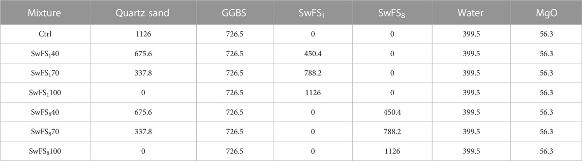
TABLE 2. Mixing proportion of MASM/kg/m3.
2.4 Test methods
2.4.1 Flow table test
The fluidity of MASM mortars was tested using a STNLD-3 fluidity tester, according to ASTM C1437 (ASTM C1437, 2015). Two orthogonal directions of the spread mortar were measured to determine the average diameter as the fluidity.
2.4.2 Compressive strength and microstructure
The compressive strength of mortars was measured on cubic specimens with a size of 50 mm × 50 mm × 50 mm. The samples were first cured in a standard curing room (23 ± 2°C, RH >95%) in a mold. After 24 h, they were demolded and continuously cured in the curing room. Specimens were tested in triplicate using a 300 kN load cell with a loading rate of 0.5 kN/s to determine the average compressive strength and the standard error.
2.4.3 Pore structure
The pore structure of mortars was investigated using a MesoMR23-060V-1 Newman nuclear magnetic resonance (NMR) instrument with a magnetic field of 0.5 ± 0.05 T and a frequency of 21.3 Hz. Cylinder specimens with a size of d × h = 50 mm × 50 mm were prepared and cured in the same way as those for the compressive strength test. At the age of 28 days, the specimens were vacuum-saturated using a BSJ fully automatic saturation machine prior to the analysis.
2.4.4 Microstructure analysis
A FlexSEM1000 Scanning Electron Microscope (SEM) was used to analyze the microstructure of specimens, which were collected from the 28-day compressive strength test. They were soaked in ethanol to cease cement hydration for more than 7 days and vacuum-dried for 1 day. Prior to the analysis, a layer of gold particles was sputtered on the surface of the samples for 120 s to achieve good electrical conductivity.
2.4.5 Grid of nanoindentation
Nanoindentation testing was carried out using a Hysitron TI 950 TriboIndenter with a pyramid-shaped diamond Berkovich indenter. The specimens were collected from the 28-day compressive test of the mortars. They were first vacuum-impregnated into capsules with a diameter of 32.5 mm, filled with epoxy resin, and were cured at room temperature until the epoxy resin hardened. Subsequently, the surfaces of the specimens were polished using a CVOK-MP1AB polisher (Chen et al., 2021).
In each 8 × 8 grid indentation zone with 10 μm spacing, 64 indents were carried out. For each indent, the elastic modulus was calculated by using the Oliver and Pharr method (Oliver and Pharr, 1992). The deconvolution was performed on MATLAB via the Gaussian mixture model (GMM) based on the expectation maximization (EM) algorithm. Based on the deconvolution results, three phases were identified with a low-density Calcium silicoaluminate hydrate (C-A-S-H), high-density C-A-S-H, and unreacted GGBS (Hay et al., 2020).
3 Results and discussion
3.1 Fluidity of mortars
Table 3 presents the fluidity of mortars with and without SwFS. This shows that the incorporation of 40% or 70% SwFS1 into MASM has resulted in slight increments in the fluidity of mortars, while 100% SwFS1 reduced the fluidity. It is indicated that the fluidity of a mortar is reduced when more SwFS1 is incorporated. This may be due to the soluble properties of the coated waterglass of SwFS1, which could dissolve and initially work as a lubricant to improve fluidity. However, more waterglass would dissolve into the pore solution with the high content of SwFS1, aiding in activating the slag, resulting in a faster early solidification of the mortar and the deterioration of fluidity. In contrast, these mortars with SwFS8 are very similar and are lower than those of the control (Ctrl), indicating that the presence of SwFS8 in MASM degrades the flow properties of MASM. This may result from high-temperature calcination causing the decomposition of the waterglass layer on the surface of SwFS8, while reducing the moisture content of SwFS8, resulting in the loss of mortar fluidity.

TABLE 3. Fluidity of mortars/cm.
3.2 Compressive strengths of mortars
Figure 1 shows the compressive strengths of MASM mortars with and without SwFS. This clearly shows that the incorporation of different types of SwFS has resulted in different effects on the compressive strength of mortars. When SwFS1 has been incorporated, the compressive strength of mortars significantly increases with its content. Despite that, the 3-day and 7-day compressive strengths of SwFS140 are slightly lower than that of Ctrl; the compressive strengths of mortars with SwFS1 have been maximally increased by 74.1% at 3 days, 33.6% at 7 days, and 64.8% at 28 days. This could be due to the dissolved waterglass from SwFS1 released into the surrounding paste, which is an effective activator for MASM by providing abundant [SiO4]4- (Wang et al., 2022). Moreover, the results also suggested that MgO may be better efficient for SwFS-based alkali-activated slag since MgO as an activator provides greater operational safety compared to SwFS-based NaOH-activated slag (Fang et al., 2023) and achieved higher compressive strength compared to SwFS-based Ca(OH)2-activated slag (Wang et al., 2022).

FIGURE 1. Compressive strength of MASM mortars with and without SwFS.
In contrast, the compressive strength of SwFS8-incorporated mortars displays a slight increase with the increased content of SwFS8, while the 3-day and 7-day compressive strengths were reduced by 16.9–17.5% and 22.3–29.0%, respectively. This indicates that coated waterglass may not be dissolved and released into the surrounding paste in a similar way as SwFS1 since SwFS8 is less soluble (Wang et al., 2022). As a result, the structure of the interface of SwFS8 could be converted into a sandwich structure of paste–waterglass coating–quartz sand, which would weaken the mechanical properties of mortars. In addition, the increased compressive strength of mortars with the content of SwFS8 may suggest that some of the coated waterglass also dissolved into the surrounding paste in the lower contents.
3.3 Pore structure
Figure 2 shows the pore structure of MASM mortars. All mortars have similar distributions of pore sizes between 1–200 nm. For SwFS1-added mortars, the peak heights are lower than those of the Ctrl. The height is increased when more SwFS1 has been added, indicating the refinement in the pore structure of MASM mortars. This can be attributed to the dissolution of coated waterglass and the released [SiO4]4- into MASM pastes could facilitate the generation of extra hydration products, which not only fill the pores and cracks in the microstructure but also enhance the bonding efficiency of MASM. In addition, the profiles of the pore structure of SwFS1-added mixtures are right-shifted with reference to Ctrl when incorporating more SwFS1, implying that the presence of SwFS1 increases the pore size of MASM due to the presence of the coating of soluble waterglass. When incorporating SwFS8 into MASM, the peak heights of SwFS8-added mixtures are increased with the addition of SwFS8, indicating that the incorporation of SwFS8 could introduce more pores to the microstructure of MASM due to the sandwich structure of the interface. Furthermore, the profiles of the pore structure of SwFS8-added MASM mortars have been moved to the left side of Ctrl, indicating increased pore sizes.
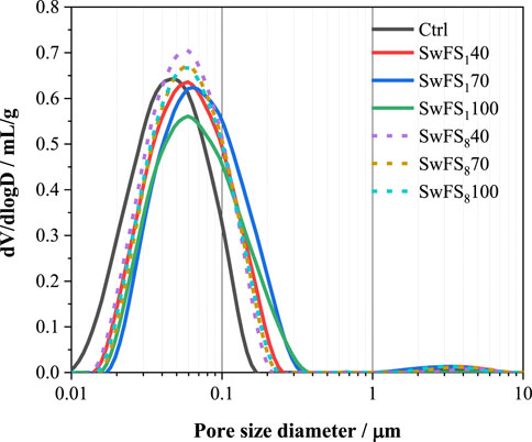
FIGURE 2. Pore structure of MASM mortars with and without SwFS.
3.4 Microstructure analysis
Figure 3 presents the typical SEM images of 28-day MASM mortars. As can be found in Figure 3A, the quartz sand displays a very smooth surface in the microstructure of Ctrl with some cracks in the interface, indicating physical bonding. In contrast, when SwFS1 has been incorporated, as shown in Figure 3B, the interface between SwFS1 and the surrounding paste has been modified very much, with no cracks. The surface of SwFS1 is rough and contains some fine particles, which may be the hydration products produced by the activation of dissolved waterglass. The extra hydration products can not only densify the microstructure of mortars but also contribute to an enhanced bonding effect between SwFS1 and the surrounding paste. In addition, some flake hydration products were also found in this figure, which could be the produced Mg(OH)2 through the hydration of MgO.
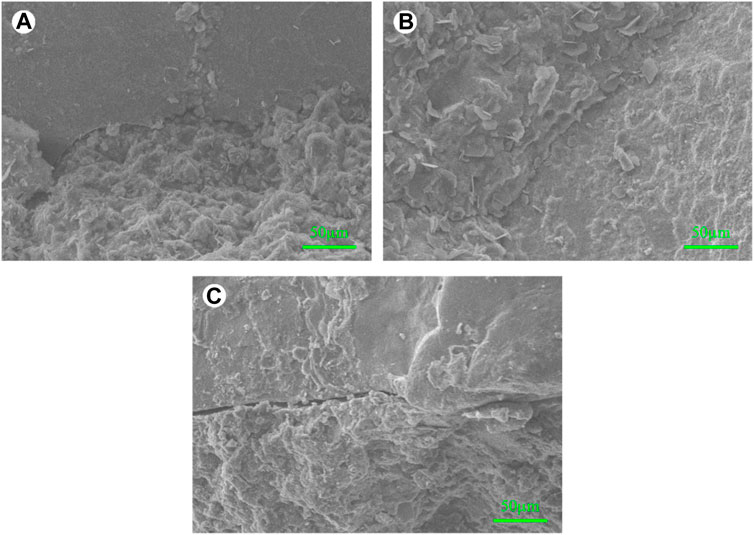
FIGURE 3. SEM images of the microstructure for 28-day MASM mortars: (A) Ctrl; (B) SwFS1100; (C) SwFS8100.
Figure 3C presents the SEM image of SwFS8100. This shows that the surface of SwFS8 is covered with fewer hydration products than that of Figure 3B. SwFS8 is poorly bonded by MASM with obvious cracks in the interface. This may be due to the lower solubility of SwFS8 since fewer hydration products can be produced through dissolved waterglass with slag. Furthermore, the presence of the hardened waterglass coating further changed the structure of the interface from a normal “aggregate–paste” to a sandwich-like interface “aggregate–waterglass–paste.” This is much related to the result of compressive strength.
3.5 Grid of nanoindentation
Nanoindentation was carried out to further investigate the role of the waterglass coating of SwFS in the micromechanical properties of 28-day MASM. Figures 4A–C show the optical microscope images of the interface of Ctrl, SwFS1100, and SwFS8100, respectively. The difference between the samples is that SwFS8100 has an obvious black stripe between SwFS8 and MASM pastes, which could be related to the file epoxy resin granules in pores or cracks during the polishing process for nanoindentation samples. The indented area is a 7 × 7 lattice distribution, with a section of approximately 10 μm in the interface. The results of the corresponding indented area were obtained in contour mapping analysis, as shown in Figures 4D–F. Figures 4A, Dshow a strong interface between quartz sand and MASM pastes, where the elastic modulus is approximately 20–60 GPa. This similar interface is also found in SwFS1100 (Figure 4E), and the size of this zone in the interface is wider and gentler than that in Ctrl, indicating some positive effects of waterglass on the microstructure of the interface. A popular explanation is the substantial accumulation of homogeneous hydration products in the interface, as [SiO4]4- dissolved from waterglass can rapidly react with Ca or Mg to generate more hydration products, especially in the interface. However, Ma et al. (2022) indicated that this rapid hydration reaction could form incompletely dissolved waterglass, which is attributed to dense precipitations (mainly calcium silicate) outside waterglass. In MASM, Ca2+ and Mg2+ may compete to bond with [SiO4]4- (Li et al., 2022). The hydration reaction may prefer the formation of magnesium silicate precipitates due to the presence of abundant MgO. This may change the composition of precipitation outside waterglass. As a result, the waterglass of SwFS1 may be completely dissolved in MASM, and SwFS1100 presented a gentle and continuous interface microstructure.
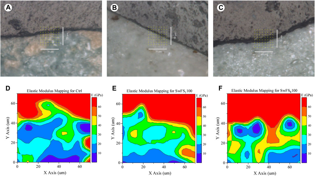
FIGURE 4. Nanoindentation results of MASM in the interface: (A,B,C) analysis region of Ctrl, SwFS1100, and SwFS8100, respectively; (D,E,F) elastic modulus mapping for Ctrl, SwFS1100, and SwFS8100, respectively.
In contrast, the interface of SwFS8100 is highly inhomogeneous. Some areas (<10 GPa) are located between SwFS8 and MASM pastes, indicating that the hydration products did not fill the whole pores in the interface even at 28 days. Porous interfaces may have a negative effect on the performance of SwFS8-added mortars. However, the waterglass of SwFS8 is not entirely detrimental to the micromechanical properties at the interface. Since SwFS8 was calcined at a high temperature, waterglass is transformed into a hardened shell of waterglass, which adheres to the outer surface of SwFS8 (Subasri and Näfe, 2008). This hardened coating can also be observed near SwFS8 in Figure 4F, and its elastic modulus is approximately 20–60 GPa.
Thereafter, deconvolution was carried out to identify hydration products of pastes around aggregates as shown in Figures 5A, C. Although Hydrated magnesium silicaluminate (M-A-S-H) is a hydration product presented in MASM, its content is much less than that of C-A-S-H (Kim et al., 2022). The coordination of Mg in M-A-S-H is easily replaced by Ca to generate new C-A-S-H (Li et al., 2022; Ma et al., 2022). Therefore, deconvolution results were only analyzed for the main hydration products (C-A-S-H gels) and un-hydrated GGBS. Three phases can be obtained from nanoindentation testing for Ctrl, SwFS1100, and SwFS8100, which are C-A-S-H, crystals of slag, and unreacted slag. In these figures, π represents the volume fraction of the phase, μ represents the mean value (in GPa), and σ represents the standard deviation (in GPa). When adding SwFS1, the average elastic moduli of C-A-S-H of SwFS1100 were significantly increased by 19.6%, which could explain the enhanced compressive strength of mortars. Nevertheless, SwFS8100 displays a poor interface with a much thicker layer of crystals with average elastic moduli of approximately 40–50 GPa, which may be due to the hardened waterglass and the formed Mg(OH)2, reflecting the complex structure of the interface.
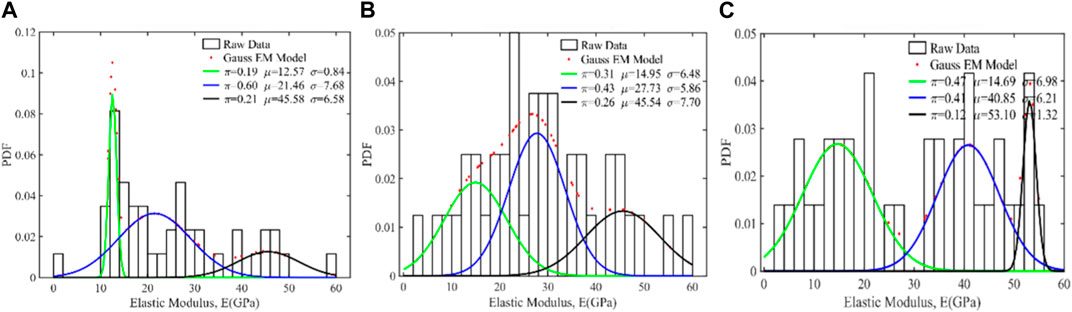
FIGURE 5. Deconvolution results of the elastic modulus for MASM: (A) Ctrl; (B) SwFS1100; (C) SwFS8100.
4 Conclusion
This paper investigated the effects of SwFS subjected to different treating temperatures (100°C and 800°C) on the performance of MASM mortars. The result showed that coated waterglass of SwFS played an important role in affecting the performance of MASM mortars. For SwFS1, some of the coated waterglass can be dissolved into the surrounding paste to activate GGBS along with MgO. As a result, mortars with SwFS1 have developed obviously, and compressive strengths increased by 33.6–74.1% at all ages. In contrast, for SwFS8 subjected to an elevated treating temperature, coated waterglass can hardly dissolve during the hydration of MASM. Thus, the resulting compressive strength is reduced with reference to mortars with SwFS1. In addition, the study of micromechanical properties showed that since more hydration products were allowed to be precipitated in the interface of SwFS1-added mortars, the average elastic moduli of C-A-S-H increased by approximately 19.6%.
Data availability statement
The original contributions presented in the study are included in the article/Supplementary Material; further inquiries can be directed to the corresponding author.
Author contributions
SH: methodology, investigation, writing, and supervision. WZ: investigation and methodology. All authors contributed to the article and approved the submitted version.
Funding
This study was funded by the Anhui Province Science and Technology Plan Project of Housing Urban-Rural Construction (2022-SF001).
Conflict of interest
Author WZ is employed by Huainan Jianfa Construction Engineering Testing Co., Ltd.
The remaining author declares that the research was conducted in the absence of any commercial or financial relationships that could be construed as a potential conflict of interest.
Publisher’s note
All claims expressed in this article are solely those of the authors and do not necessarily represent those of their affiliated organizations, or those of the publisher, the editors, and the reviewers. Any product that may be evaluated in this article, or claim that may be made by its manufacturer, is not guaranteed or endorsed by the publisher.
References
Ashish, D. K., Verma, S. K., Ju, M., and Sharma, H. (2023). High volume waste foundry sand self-compacting concrete – transitioning industrial symbiosis. Process Saf. Environ. Prot. 173, 666–692. doi:10.1016/j.psep.2023.03.028
ASTM C1437 (2015). Standard test method for flow of hydraulic cement mortar. West Conshohocken, PA: ASTM International.
Bhardwaj, B., and Kumar, P. (2017). Waste foundry sand in concrete: A review. Constr. Build. Mater. 156, 661–674. doi:10.1016/j.conbuildmat.2017.09.010
Chen, P., Zhang, L., Wang, Y., Fang, Y., Zhang, F., and Xu, Y. (2021). Environmentally friendly utilization of coal gangue as aggregates for shotcrete used in the construction of coal mine tunnel. Case Stud. Constr. Mater. 15, e00751. doi:10.1016/j.cscm.2021.e00751
Díaz Pace, D. M., Miguel, R. E., Di Rocco, H. O., Anabitarte García, F., Pardini, L., Legnaioli, S., et al. (2017). Quantitative analysis of metals in waste foundry sands by calibration free-laser induced breakdown spectroscopy. Spectrochim. Acta Part B At. Spectrosc. 131, 58–65. doi:10.1016/j.sab.2017.03.007
Dyer, P. P. O. L., and De Lima, M. G. (2022). Waste foundry sand in hot mix asphalt: A review. Constr. Build. Mater. 359, 129342. doi:10.1016/j.conbuildmat.2022.129342
Fang, J., Xie, J., Wang, Y., Tan, W., and Ge, W. (2023). Alkali-activated slag materials for bulk disposal of waste waterglass foundry sand: A promising approach. J. Build. Eng. 63, 105422. doi:10.1016/j.jobe.2022.105422
Ghanizadeh, A. R., Tavana Amlashi, A., and Dessouky, S. (2023). A novel hybrid adaptive boosting approach for evaluating properties of sustainable materials: A case of concrete containing waste foundry sand. J. Build. Eng. 72, 106595. doi:10.1016/j.jobe.2023.106595
Hay, R., Li, J., and Celik, K. (2020). Influencing factors on micromechanical properties of calcium (alumino) silicate hydrate C-(A-)S-H under nanoindentation experiment. Cem. Concr. Res. 134, 106088. doi:10.1016/j.cemconres.2020.106088
Javed, S., Lovell, C., and Wood, L. E. (1994). Waste foundry sand in asphalt concrete. Washington, D.C.: Transportation research record.
Kim, G., Im, S., Jee, H., Suh, H., Cho, S., Kanematsu, M., et al. (2022). Effect of magnesium silicate hydrate (M-S-H) formation on the local atomic arrangements and mechanical properties of calcium silicate hydrate (C-S-H): in situ X-ray scattering study. Cem. Concr. Res. 159, 106869. doi:10.1016/j.cemconres.2022.106869
Kavitha, O. R., Shyamala, G., and Akshana, V. (2021). Study of sustainable concrete property containing waste foundry sand. Mater. Today Proc. 39, 855–860. doi:10.1016/j.matpr.2020.10.359
Khan, M. M., Mahajani, S. M., Jadhav, G. N., Vishwakarma, R., Malgaonkar, V., and Mandre, S. (2021). A multistakeholder approach and techno-economic analysis of a mechanical reclamation process for waste foundry sand in the Indian context. Resour. Conservation Recycl. 167, 105437. doi:10.1016/j.resconrec.2021.105437
Kraus, R. N., Naik, T. R., Ramme, B. W., and Kumar, R. (2009). Use of foundry silica-dust in manufacturing economical self-consolidating concrete. Constr. Build. Mater. 23, 3439–3442. doi:10.1016/j.conbuildmat.2009.06.006
Li, J., Nong, Y., Yin, S., Chen, Z., Su, T., and Yu, Q. (2022). Calcium and magnesium silicate hydrates formed in the presence of sodium hydroxide: insight from experiments and DFT simulation. Mater. Today Commun. 33, 104362. doi:10.1016/j.mtcomm.2022.104362
Liu, S., and Zheng, W. (2023). Experimental and numerical study for the bending behaviour of UHPC beams with waste foundry sand. J. Build. Eng. 69, 106284. doi:10.1016/j.jobe.2023.106284
Ma, H., Zhang, S., and Feng, J. (2022). Early hydration properties and microstructure evolutions of MgO-activated slag materials at different curing temperatures. Ceram. Int. 48, 17104–17115. doi:10.1016/j.ceramint.2022.02.266
Martins, M. A. B., Silva, L. R. R., Kuffner, B. H. B., Barros, R. M., and Melo, M. L. N. M. (2022). Behavior of high strength self-compacting concrete with marble/granite processing waste and waste foundry exhaust sand, subjected to chemical attacks. Constr. Build. Mater. 323, 126492. doi:10.1016/j.conbuildmat.2022.126492
Mohamed Ismail, A. A., Kannadasan, K., Pichaimani, P., Arumugam, H., and Muthukaruppan, A. (2020). Synthesis and characterisation of sodium silicate from spent foundry sand: effective route for waste utilisation. J. Clean. Prod. 264, 121689. doi:10.1016/j.jclepro.2020.121689
Oliver, W. C., and Pharr, G. M. (1992). An improved technique for determining hardness and elastic modulus using load and displacement sensing indentation experiments. J. Mater. Res. 7, 1564–1583. doi:10.1557/JMR.1992.1564
Rodrigues, V. S., Andrade, L. M., and Tenório, J. A. S. (2021). Biodegradation of phenolic compounds in waste foundry sand: physical and chemical characterization of foundry sand and bacterial degradation kinetics. Environ. Nanotechnol. Monit. Manag. 16, 100575. doi:10.1016/j.enmm.2021.100575
Siddique, R., and Singh, G. (2011). Utilization of waste foundry sand (WFS) in concrete manufacturing. Resour. Conservation Recycl. 55, 885–892. doi:10.1016/j.resconrec.2011.05.001
Subasri, R., and Näfe, H. (2008). Phase evolution on heat treatment of sodium silicate water glass. J. Non-Crystalline Solids 354, 896–900. doi:10.1016/j.jnoncrysol.2007.08.037
Wang, C., Chen, P., Xu, Y., Zhang, L., Luo, Y., Li, J., et al. (2022). Investigation on the utilization of spent waterglass foundry sand into Ca(OH)2-activated slag materials considering the coating layer of dried waterglass. Constr. Build. Mater. 329, 127180. doi:10.1016/j.conbuildmat.2022.127180
Keywords: waste foundry sand, MgO-activated slag material, spent waterglass foundry sand, compressive strength, elastic moduli
Citation: Hu S and Zhang W (2023) Effect of spent waterglass foundry sand on the performance of MgO-activated slag materials. Front. Mater. 10:1207246. doi: 10.3389/fmats.2023.1207246
Received: 17 April 2023; Accepted: 21 September 2023;
Published: 03 October 2023.
Edited by:
Mehran Khan, University College Dublin, IrelandReviewed by:
Nahla Hilal, University of Fallujah, IraqCristina Leonelli, University of Modena and Reggio Emilia, Italy
Kinga Korniejenko, Cracow University of Technology, Poland
Copyright © 2023 Hu and Zhang. This is an open-access article distributed under the terms of the Creative Commons Attribution License (CC BY). The use, distribution or reproduction in other forums is permitted, provided the original author(s) and the copyright owner(s) are credited and that the original publication in this journal is cited, in accordance with accepted academic practice. No use, distribution or reproduction is permitted which does not comply with these terms.
*Correspondence: Shuimu Hu, MjAwNDAzNkBhdXN0LmVkdS5jbg==