 Guoqi Xing
 Yupeng Cao
 Baoliang Zhang2
- 1School of Civil and Architectural Engineering, Weifang University, Weifang, Shandong, China
- 2School of Civil and Architectural Engineering, Liaocheng University, Liaocheng, Shandong, China
To make a new type of double-plate vertically loaded anchor (DPVLA) penetrate into clay deeper, the influence of parameters on the ultimate penetration depth of DPVLAs in soft clay should be investigated. The expression of the ultimate penetration depth applicable to DPVLAs in clay was determined in terms of the formula of the ultimate penetration depth of anchors with a wedge-shaped section. Based on the drag penetration tests, the movement direction of the bottom fluke of DPVLAs with different lengths of the bottom fluke and different included angles was obtained. By the finite-element method, the upper bound solutions of bearing capacity factors of DPVLAs with different included angles and different lengths of the bottom flukes were also obtained, which correspond to the maximum penetration depth induced by the initial orientation of the anchor. According to the determined expression of the ultimate penetration depth of DPVLAs, the ultimate penetration depth of DPVLAs with different included angles and different lengths of the bottom fluke in clay can be calculated. The results showed that increasing the length of the bottom fluke can increase the ultimate penetration depth when the included angles were the same for DPVLAs not only in the clay with zero strength at the seabed but also in the clay with uniform strength. However, when the length of the bottom fluke is the same, increasing the included angle of DPVLAs in clay can significantly reduce the ultimate penetration depth.
1 Introduction
Vertically loaded anchors (VLAs) are widely employed in the mooring system for deep waters platforms due to the high pullout capacity and low installation cost of VLAs (Aubeny, and Murff, 2005; Aubeny and Chi, 2010). In addition, VLAs can simultaneously withstand horizontal and vertical loads compared with the conventional drag embedment anchors which only withstand the horizontal load (Yang et al., 2010). When VLAs are penetrated into the specified position in the seabed, then the anchor line can be reconfigured to be normal to the fluke, which induces a higher pullout capacity than the conventional drag embedment anchors (Tian et al., 2015). To enhance the pullout capacity of VLAs, the area of the anchor plate of VLAs should be increased. However, the larger area of the anchor plate cannot be conveniently penetrated into the seabed (Liu et al., 2010b). Therefore, it is not feasible to only increase the area of the anchor plate to increase the pullout capacity of VLAs. To effectively increase the pullout capacity of anchors, a new type of anchor was put forward by the authors, as illustrated in Figure 1 (Xing et al., 2020). Furthermore, experiments have been carried out to find that the ultimate loading capacity of double-plate VLAs (DPVLAs) in the sand is greater than that of VLAs by about 30.0% (Xing et al., 2021). In addition, it is also found that the ultimate loading capacity increases with the increase in included angle. However, when the included angle of the DPVLA is greater than 30°, it cannot conveniently penetrate into the soil in model tests (Xing et al., 2021). In the follow-up studies, the authors improve the dragging penetration method, which can make the included angle greater than 30° in the penetration tests. The improved dragging penetration method will be introduced in the following section.
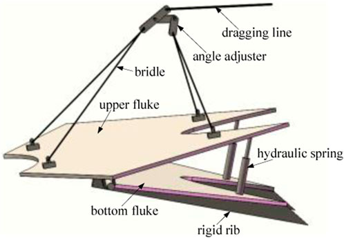
FIGURE 1. Double-plate vertically loaded anchors (Xing et al.,2020).
The ultimate loading capacity of anchors is related to the ultimate penetration depth as shown in Figure 2, and the deeper the anchor penetrates, the higher the ultimate loading capacity (O’Neill et al., 1997). Therefore, the ultimate penetration depth is an important parameter for anchors, and some researchers have investigated it (Neubecker and Randolph, 1995; Neubecker and Randolph, 1996; Ruinen and Degenkamp, 2002; Miedema et al., 2007; Liu et al., 2010a).
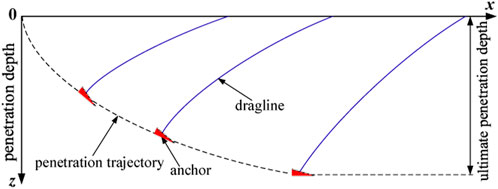
FIGURE 2. Penetration trajectory of the anchor in soil.
Currently, empirical design charts are widely used to evaluate the ultimate penetration depth of anchors in clay and sand (NCEL, 1987; Vryhof Anchors, 2005). However, the empirical design charts do not take into account the properties of the soil, anchor, and dragline, and they cannot ensure the accuracy of prediction of the ultimate penetration depth of anchors.
Ruinen and Degenkamp (2002) and Miedema et al. (2007) employed numerical calculation methods to reveal some parameters influencing the ultimate penetration depth. However, the results showed that the differences in the prediction results of the ultimate penetration depth were substantial because numerical procedures used by the predictors were different (Murff et al., 2005). The studies indicate that numerical calculation methods are not credible in predicting the ultimate penetration depth.
For the soft clay with the strength represented by
where ZUED represents the ultimate penetration depth; k is the gradient of undrained shear strength of clay with depth; d is the diameter of embedded draglines; A is the fluke area of the anchor; and θs is the angle of the shank to the top surface of the fluke of an anchor. It is also illustrated that Eq. 1 does not consider soil conditions, the type of the anchor, the type and size of the anchor forerunner, the fluke angle of the anchor, and the uplift angle at the surface of the seabed. Therefore, Eq. 1 is not widely applied up to now.
For the soft clay with the strength represented by
where f is the form factor of the anchor; b is the effective width of the embedded dragline; θw is the drag angle to the fluke at the shackle of the weightless anchor; Ap is the projected anchor area; and ηw is the efficiency factor, which can be expressed as ηw = Tw/W, where W is the submerged weight of the anchor and Tw is the drag force at the shackle of the weightless anchor. Therefore, if the abovementioned parameters are known, the ultimate penetration depth of anchors can be calculated with Eq. 2. However, Eq. 2 does not apply the most common strength profile because the expression of the strength of the clay is only suitable for the soil with strength
By analyzing the equilibrium forces acting on the anchor and embedded dragline, and the interaction between them at the ultimate penetration depth, Liu et al. (2010a) derived the concise expressions of the ultimate penetration depth of VLAs in soft clay as follows:
where m=(m1Ab + m2As)/(2b) m1 = Ncf(θa-θm)2/[Nclcos(θa-θm)] m2 = αf(θa-θm)2/[Nclcos(θa-θm)], in which Δz is the distance from the shackle to the plane of the anchor fluke; Ab is the total projected area of the anchor at the ultimate penetration depth onto the plane perpendicular to the horizontal, including the shank and fluke; and As is the total shear area of the anchor at the ultimate penetration depth along the horizontal, including the shank and fluke. Ncf and Ncl are the bearing capacity factors of the anchor and dragline in clay, respectively; θa and θm are the drag angle to the top surface of the fluke and the angle of the top surface of the fluke to the movement direction at the ultimate penetration depth, respectively; and αf represents the adhesion factor of the anchor. In addition, Eq. 3 was examined by other prediction formulas, and the credibility of the expression of the ultimate penetration depth of anchors in clay has been verified.
For the new type of anchor-DPVLA, it is very necessary to reveal the ultimate penetration depth and the influence of parameters on the ultimate penetration depth of DPVLAs. In this paper, the expression of the ultimate penetration depth applicable to DPVLAs in clay was determined and two parameters, such as the included angle and the length of bottom fluke, relating to the ultimate penetration depth of DPVLAs were obtained through laboratory model test and finite-element analysis. Moreover, the influence of the included angle and the length of the bottom fluke of DPVLAs was investigated based on the determined expression of the ultimate penetration depth.
2 Ultimate penetration depth applicable to DPVLA in clay
2.1 Improved penetration method for DPVLA in soil
When the anchor is dragged into the position of the ultimate penetration depth, the resistant force acting on the anchor is shown in Figure 3, where Ta represents the drag force at the shackle; Tv and Th are the vertical and horizontal components of Ta, respectively; Fbs and Fbf are the end bearings on the shank and fluke in the horizontal, respectively; Fss and Fsf are shear forces on the shank and fluke in the horizontal, respectively; and θm represents the angle of the top surface of the fluke to the horizontal. Based on the abovementioned forces acting on the anchor and embedded dragline in Figure 3, Liu et al. (2010a) derived the expression of the ultimate penetration depth of the anchor in soft clay as Eq. 3.
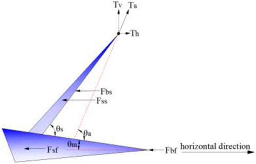
FIGURE 3. Diagram of resistant force acting on the anchor in the horizontal direction at the ultimate penetration depth (Liu et l.,2010a).
To make the included angle of DPVLAs greater than 30° and make it conveniently penetrate the soil, an improved penetration method was put forward, as illustrated in Figure 4. As shown in Figure 4A, the installation method in the first stage is the same as the conventional anchors. In the first stage of installation, the soil is filled in the space between the upper and bottom flukes, as illustrated in Figure 5, and the shape of DPVLAs in the ultimate penetration depth is similar to that of anchors with a wedge-shaped section in Figure 3. Therefore, the improved penetration method of DPVLAs also contributes to the penetration of anchors. In the second stage of installation, when the anchor is dragged to the ultimate penetration depth, then the DPVLA moves in the opposite direction of movement, as shown in Figure 4B, which can induce the increase of the included angle of DPVLAs, i.e., improve the ultimate pullout capacity of DPVLAs (Xing et al., 2021). Therefore, the modified penetration method not only contributes to the penetration of DPVLAs in soil but also improves the ultimate pullout capacity of DPVLAs.
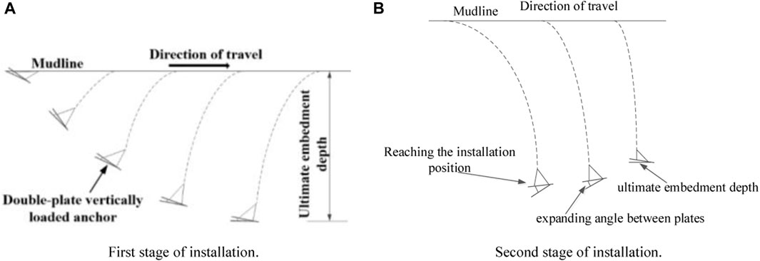
FIGURE 4. Installation method for DPVLAs in the seabed. (A) First stage of installation. (B) Second stage of installation.
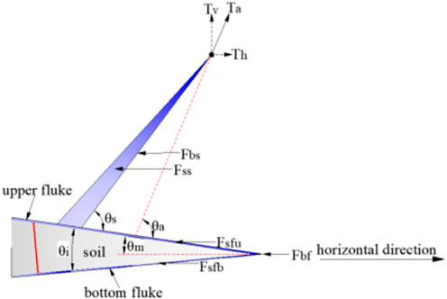
FIGURE 5. Improved penetration method for DPVLAs.
2.2 Ultimate penetration depth applicable to DPVLAs in clay
The resistant forces acting on the DPVLA in Figure 5A are almost the same as those in Figure 3 except that the shear forces acting on the upper and bottom flukes of the DPVLA in the horizontal, Fsfu and Fsfb, in Figure 5A. Since the shape and the resistant forces of DPVLAs are almost the same as that of anchors with a wedge-shaped section in the improved penetration method, Eq. 3 can be considered to be also applicable to the DPVLA at the ultimate penetration depth. However, the effective shear area of DPVLAs, As, is different from that of VLAs in Eq. 3, which can be expressed as the sum of the effective shear area of the upper and bottom flukes, i.e., As= Asu + Asb.
Since DPVLAs is a new type of anchor, the bearing capacity factors of the DPVLA in clay are also different from those of the conventional dragging anchor. Therefore, the bearing capacity factor, Ncf, applicable to VLAs in Eq. 3, should be replaced by the bearing capacity factors of DPVLAs in clay, Ncd. In the following section, the bearing capacity factors of the DPVLA in clay will be discussed. For the lack of knowledge of the bearing capacity factor, Liu et al.(2010a) adopted Ncf = Ncl in Eq. 3. In this section, the bearing capacity factors of DPVLAs and dragline, Ncd and Ncl, are also not distinguished, i.e., Ncd = Ncl. Therefore, the expressions of m1 and m2 in Eq. 3 can be revised as follows:
When
In this paper, we only discuss two special cases of clay; the first, suo = 0 or η = 0, and Eq. 6 can be further simplified as follows:
and the second, the strength of clay is uniform; in this case, k = 0 or η = ∞, and Eq. 6 can be simplified as follows:
2.3 Movement directions of the bottom fluke of DPVLA models
It is shown in Eq. 6 that the movement direction, θm, of the bottom fluke of DPVLAs at the ultimate penetration depth is an important parameter; therefore, it should be determined. For the VLA with a wedge-shaped section, Liu et al. (2010a) carried out experiments to investigate the possible movement directions of the fluke at the ultimate penetration depth and found that the accurate direction of movement of the fluke was difficult to obtain. In this section, through the laboratory model tests, the movement direction of the bottom fluke of DPVLAs with different lengths of the bottom fluke and different included angles in clay at the ultimate penetration depth was determined.
2.3.1 Anchor model
To investigate the influence of the length of the bottom fluke of DPVLAs on the movement directions of the bottom fluke at the ultimate penetration depth, the length of the bottom fluke of DPVLA models was set to 80 mm, 100 mm, and 120 mm, respectively. In addition, the width of the bottom fluke of DPVLA models was all set to 120 mm. For the dimensions of the upper bottom of DPVLA models, they were all set such that the length and width of the upper fluke were all 120 mm. Moreover, the thickness of the fluke was set to 2.0 mm.
To investigate the influence of the included angle of DPVLAs on the movement directions of bottom fluke at the ultimate penetration depth, the included angle (angle between the upper and bottom fluke) of DPVLA models was set 10°, 20°, and 30°, respectively. The magnitude of the included angle was controlled by a bolt as shown in Figure 6. One end of the bolt was connected to the bottom fluke, which can rotate about the bottom fluke; the other end of the bolt passed through the upper fluke, and the screw nut was on the end of the bolt, which can adjust the length of the bolt.
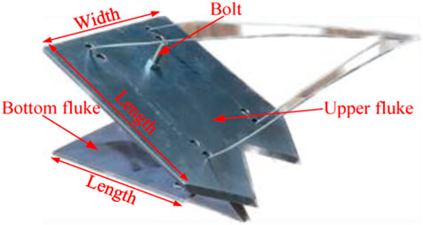
FIGURE 6. DPVLA model used in tests.
2.3.2 Model experimental system
Figures 7A–C show the drag penetration test system for the DPVLAs, which includes an experimental flume, drag system, measurement system, and data acquisition system.
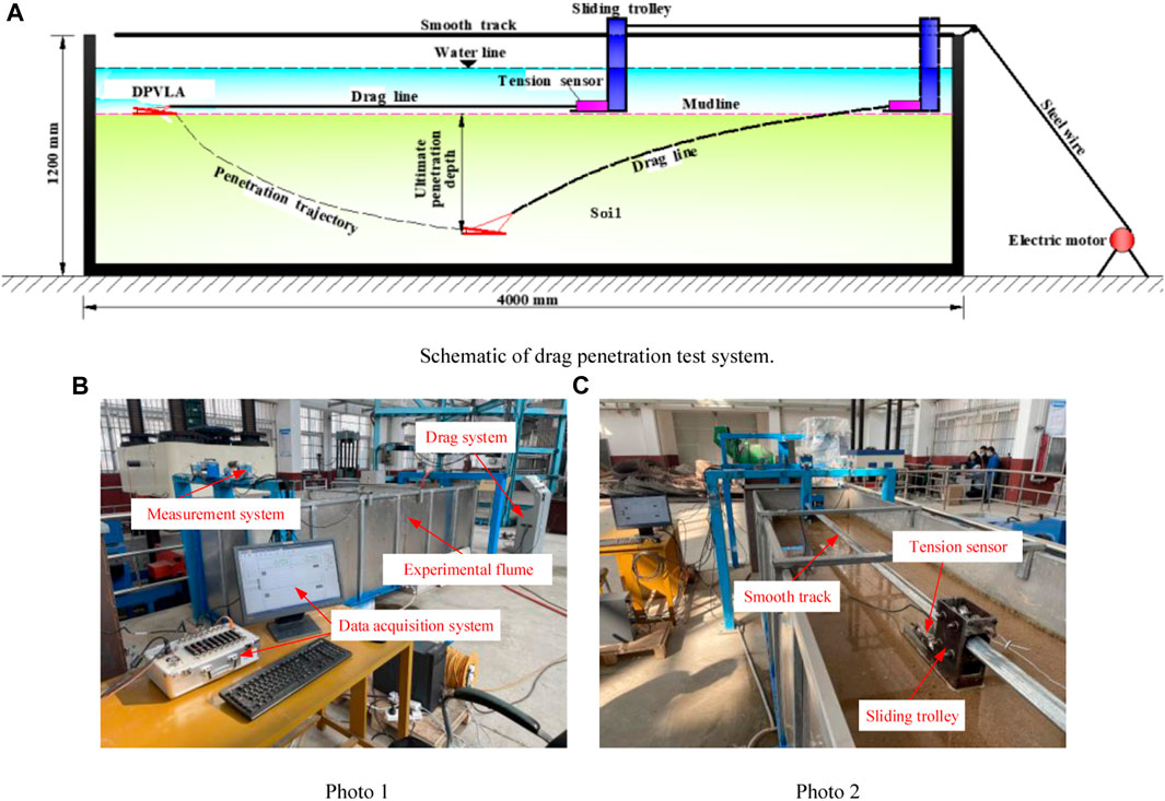
FIGURE 7. Setup of the drag penetration test system. (A) Schematic of the drag penetration test system. (B) Photo 1. (C) Photo 2.
In the drag penetration test system, water and fine sand were filled in the experimental flume to simulate the seabed environment. In the drag penetration test, DPVLA models penetrated the simulated seabed environment by the dragging force, then gradually increasing to reach the maximum penetration depth in the experimental flume, as illustrated in Figure 7A. Since the height of fine sand should exceed 5.0B (where B represents the length of anchor fluke, i.e., 120 mm) (Ruinen and Degenkamp, 2001), and the height of water above the fine sand surface did not exceed 500 mm, the height of the experimental flume in the drag penetration test system was set to 1,200 mm. To avoid side effects, the width of the experimental flume should be sufficiently wide (i.e., greater than 6.0B) (Liu et al., 2010b) so that the side walls of the experimental flume cannot influence the penetration of DPVLA models; therefore, the width of the experimental flume was set to 1,000 mm. To ensure that the DPVLA model could reach the ultimate penetration depth, the length of the experimental flume should be sufficiently long. Murff et al. (2005) considered that the length of the experimental flume should exceed 30.0B; therefore, it was set to 4,000 mm in the drag penetration test system.
In addition, to control the water level and drain, four drain valves were installed at the bottom of the experimental flume. Moreover, gravels with the particle size range of 15–20 mm were scattered uniformly to the bottom of the flume with about 6.0 cm thickness, and it can ensure that the water level uniformly dropped during drainage by opening the valves.
The drag system was used to exert the dragging force by using an electric motor, and the dragging force was applied to the DPVLA models through a steel wire, as illustrated in Figure 7A. The electric motor can control the dragging speed of the DPVLA models, and the dragging speed of the DPVLA models was set to 20 mm/s in the drag penetration test.
2.3.3 Sand used in tests
To make the water quickly drain from the model experimental system, natural fine sand was used in the drag penetration test of DPVLA models. The particle size distribution curve of fine sand used in tests is shown in Figure 8, and it indicates that the sand is poorly graded and relatively uniform, which is suitable for the consistent testing condition in the drag penetration test system. For the granular materials, Bai et al. (2017) and Bai et al. (2021) investigated the physical–chemical interaction between particles and the phenomenon of particle reorganization. The physical properties of fine sand were obtained in terms of standard tests and listed in Table 1.
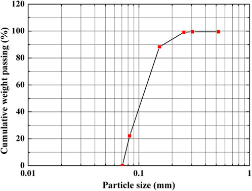
FIGURE 8. Particle size distribution curve.

TABLE 1. Physical parameters of fine sand used in the finite-element model.
2.3.4 Testing procedure
In the drag penetration test, the initial orientations of the bottom fluke of DPVLA models with different lengths of the bottom fluke and different included angles were all set to 0°; i.e., the bottom fluke of DPVLA models were placed horizontally on the simulated surface of the seabed. To ensure the repeatability of experiments, maintaining the relative density of fine sand in the same state is crucial. Therefore, before each test, the fine sand in the experimental flume was loosened to a depth of approximately 3.0 times the length of the anchor fluke to obtain the same stress level. Then, the DPVLA model was placed on the surface of the fine sand and water was poured into the experimental flume until its level was 200 mm higher than the surface of fine sand. Finally, the drain valve was opened until the water level was 100 mm above the surface of the fine sand. The penetration test of DPVLA models should be terminated if the dragging force was maintained constant.
2.3.5 Test results
The test results showed that when the ultimate penetration depths of the DPVLA model with different lengths of the bottom fluke and different included angles were reached, the movement directions of the bottom fluke of DPVLA models were all almost parallel to the surface of fine sand, as illustrated in Figure 9; i.e., θm is equal to θi. The results also show that the length of the bottom fluke and the included angle of DPVLA models have little influence on the movement directions of the bottom fluke at the ultimate penetration depth.
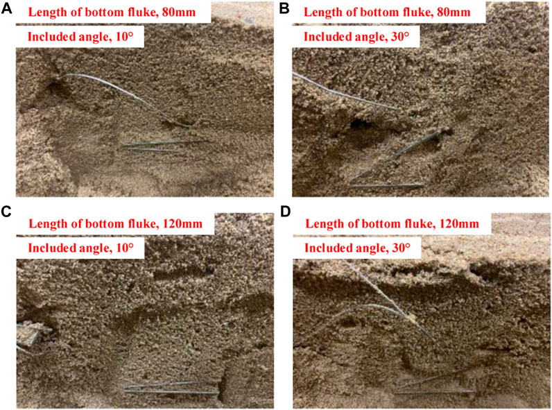
FIGURE 9. State of DPVLA at the ultimate penetration depth. (A) Photo 1; (B) Photo 2; (C) Photo 3; (D) Photo 4
2.4 Bearing capacity factors for DPVLAs in clay
The bearing capacity factor, Ncd, in Eq. 6 is also an important parameter of DPVLAs, which influences the ultimate penetration depth of DPVLAs in clay. However, the bearing capacity factor, Ncd, in Eq. 6 is different from that of VLAs. Therefore, it is necessary to investigate the bearing capacity factor of DPVLAs with different lengths of the bottom fluke and different included angles in clay.
For the bearing capacity factor, Ncf, of the VLA in clay in Eq. 3, it can be obtained through the following expression (Det Norshke Veritas, 2002):
where Fu is the ultimate pullout capacity of anchors; A is the bearing area of the fluke of anchors; and su is the undrained shear strength of clay located in the place where the anchor is embedded.
Equation 9 also can be applied to the DPVLA. However, the area of the fluke of DPVLAs is different from that of the VLA. As illustrated in Figure 10, the effective bearing area of the fluke of DPVLAs, Ad, can be expressed as follows:
where Au and Ab are the area of the upper and bottom fluke of DPVLAs in clay, respectively, and θi is the included angle of DPVLAs. When determining the bearing capacity factor of the DPVLA in clay, the effective bearing area of fluke, A, in Eq. 9 should be replaced by Ad.
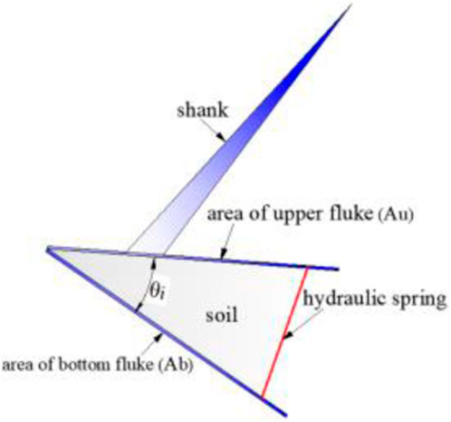
FIGURE 10. Scheme of DPVLA at the state of mooring.
However, Eq. 3 does not take into account the effects of the initial orientation of the anchor, which also affects the ultimate penetration depth of the anchor (Liu et al., 2010b). It is known that if the anchor fluke is initially set on the seabed at a shallow angle to the horizontal, the anchor will not reach its full embedment depth. However, the ultimate penetration depth is related to the ultimate pullout capacity of anchors. To obtain the maximum ultimate pullout capacity of DPVLAs, the ultimate penetration depth should also be the maximum. Therefore, to obtain the maximum ultimate pullout capacity, the upper bound solution of the ultimate pullout capacity of the DPVLA in clay should be considered. In addition, the finite-element method is utilized in this section to obtain the upper bound solution of the ultimate pullout capacity of the DPVLA in clay.
2.4.1 Three-dimensional finite-element model
Figure 11 represents the three-dimensional finite-element model along with meshes for the upper bound solution. The ZSOIL.PC software was used in the finite-element analysis, and eight-node continuum brick elements for both clay and DPVLAs were used in the three-dimensional finite-element model. In the plane strain condition, to avoid the boundary effects, the computational region of soil in length and width directions should be within about 16.0B and the computational region of soil in depth direction was not less than 5.0B, where B was the length of the fluke of anchors (Merrifield et al., 2001). To eliminate far-away boundary in the three-dimensional finite-element model, the computational region of soil in length and width directions were all set to 21.0B, and the computational region of soil in the depth direction was set to 8.0B, where B was the length of the upper fluke of the DPVLA, as indicated in Figure 11. Displacements in the x, y, and z directions at the bottom boundary were all fully fixed and horizontal displacements at the lateral boundaries were only constrained. Moreover, for the displacements at the top boundary, they were all not constrained, which simulated the surface of the seabed.
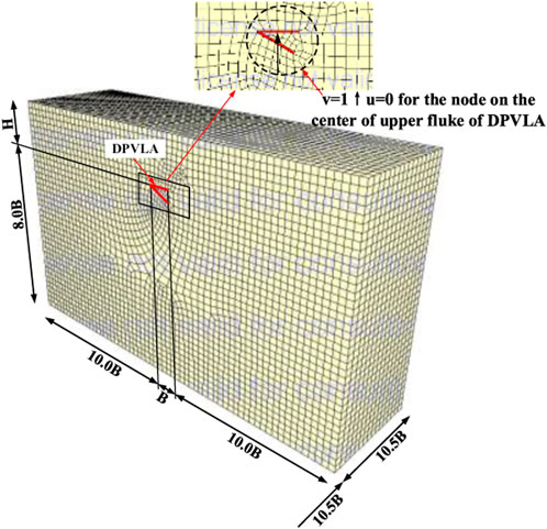
FIGURE 11. Three-dimensional finite-element model for the upper bound solution.
In the upper bound analysis of the three-dimensional finite-element model, the DPVLA was assumed to be rigid and it cannot move horizontally (u = 0); through prescribing a unit vertical velocity to the nodes on the center of the upper fluke of DPVLAs (as illustrated in Figure 11), the upper bound solution of the ultimate loading capacity of DPVLAs can be obtained. Furthermore, based on Eq. 9, the bearing capacity factors of DPVLAs can be calculated.
2.4.2 Constitutive model and parameters
The ideal elastic–plastic constitutive relationship obeying Von Mises’ yield criterion is often used to model the clay (Qiao and Ou, 2012), with untrained shear strength as
To validate the credibility of the three-dimensional finite-element model, the results obtained from the finite-element method should be compared with the test results. Ruinen (2004) carried out field tests to obtain the ultimate pullout capacity of 2,741.1 kN of VLAs. In the field tests, the embedded depth of the VLA was H = 18.0 m and the dimensions of the VLA was 3000.0 mm in length, 3000.0 mm in width, and 200.0 mm in thickness. In addition, the parameters of clay and VLA in field tests were the same as those assumed previously. Based on the three-dimensional finite-element model established previously and the parameters of clay and VLA, the curve of load vs. displacement for the VLA can be obtained, as illustrated in Figure 12. As can be seen from Figure 12, the ultimate pullout capacity of the VLA was 2,705.0 kN. Comparing the result from the three-dimensional finite-element method with the test results, the error of the ultimate loading capacity of VLAs was only 1.3%, indicating that the three-dimensional finite-element model and the parameters used in the model are all credible. Furthermore, based on Eq. 9, the bearing capacity factor of the VLA can be calculated as
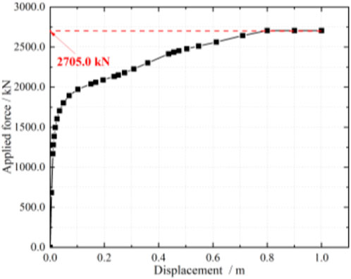
FIGURE 12. Load vs. displacement for VLAs in clay.
2.4.3 Bearing capacity factors of DPVLAs
The results from the work of Cheng et al. (2019) indicate that the ultimate pullout capacity of full-scale VLAs is higher than that of reduced-scale VLAs due to the higher overburden pressure of full-scale VLAs compared to reduced-scale VLAs. In this section, the full-scale DPVLA is utilized to obtain the ultimate pullout capacity.
In the three-dimensional finite-element model, the dimensions of the DPVLA were that the length, width, and thickness of the upper fluke of the DPVLA were 3000.0, 3000.0, and 200.0 mm, respectively, which were the same as those of the VLA as mentioned in Section 4.2. The width and thickness of the bottom fluke was the same as that of the upper fluke. To investigate the influence of the included angle and the length of the bottom fluke on the bearing capacity factors of DPVLAs, the included angles were set at 10°, 20°, 30°, 40°, 50°, 60°, 70°, and 80°, respectively, and the lengths of the bottom fluke were set 2000, 2500, and 3000 mm, respectively.
For the VLA, the critical embedded depth is about 3.0–4.5 times the length of the fluke in clay (Ruinen and Degenkamp, 2001; Det Norshke Veritas, 2002). When the embedded depth of VLAs is 18.0 m (i.e., 6.0 times the length of the fluke), it is the deeply embedded anchor and the ultimate pullout capacity of VLAs cannot increase with further increasing the penetration depth. In this section, the deeply embedded DPVLA in the three-dimensional finite-element model should also be ensured. To obtain the deeply embedded DPVLA, the embedded depths of DPVLAs were set at 18.0, 19.0, and 20.0 m, respectively. In addition, the included angle of the DPVLA was assumed to be 50°. The change of the normalized ultimate pullout capacity with embedded depth is shown in Figure 13. As illustrated in Figure 13, when the embedded depth of the DPVLA was 18.0 m, further increasing the embedded depth cannot significantly increase the ultimate loading capacity, which indicated that the DPVLA was a deeply embedded anchor at the embedded depth of 18.0 m. In the following analysis, the embedded depth of the DPVLA was all set to 18.0 m, i.e., 6B, where B represents the length of DPVLAs.
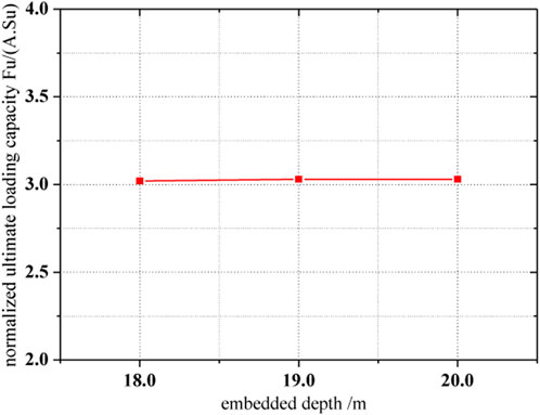
FIGURE 13. Variation of normalized ultimate loading capacity with embedded depth.
Based on the upper bound solution of the ultimate loading capacity obtained from the finite-element method, the bearing capacity factors of DPVLAs with different included angles and different lengths of the bottom fluke can be calculated with Eqs 9, 10. Figure 14 shows the influence of the included angle and the length of the bottom fluke on the bearing capacity factors. As illustrated in Figure 14, the trend of the influence of included angle on the bearing capacity factor of DPVLAs with different lengths of the bottom fluke was the same. It all showed that the bearing capacity factors of DPVLAs increased with the increase in the included angle. However, the bearing capacity factors of DPVLAs increased with the decrease in the length of the bottom fluke when the included angles were the same. In addition, with the included angle becoming larger, such as 80°, the length of the bottom fluke of DPVLAs has a minor influence on the bearing capacity factor.
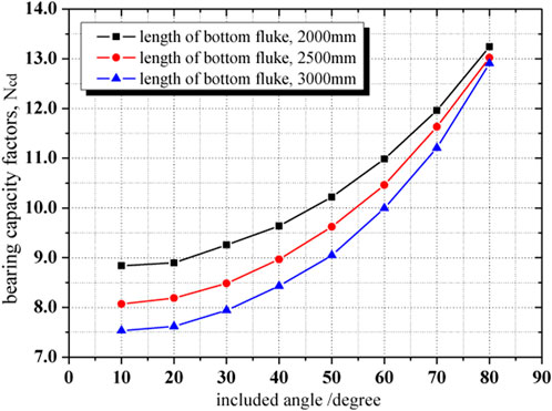
FIGURE 14. Influence of the included angle and length of the bottom fluke on the bearing capacity factor of DPVLA.
3 Parametric study
Based on Eq. 3, Liu et al. (2010a) investigated the influence of some parameters, such as the shape and dimensions of the fluke, size of the dragline, soil properties, and bearing capacity factors, on the ultimate penetration depth of VLAs in clay. In this section, based on Eqs 7, 8, the influence of the included angle and the length of the bottom fluke of DPVLAs on the ultimate penetration depth was investigated.
DPVLA models used in the parametric study were anchors with soft shanks, and the dimensions of the upper fluke of the DPVLA model were assumed to be 3000 (length) × 3000 (width)× 200 mm (thickness). Three sizes of the bottom fluke were assumed, i.e., 3000 mm × 3000 mm × 200 mm, 2500 mm × 3000 mm × 200 mm, and 2000 mm × 3000 mm × 200 mm. The distance from the shackle to the gravity center of the upper fluke, l0, for the DPVLA model was assumed to be 3600 mm. The distance from the shackle to the plane of the upper fluke of DPVLAs, Δz, can be approximately calculated with Δz = l0sinθa. For the adhesion factor, αf, in Eq. 3, Det Norshke Veritas (2000) and Det Norshke Veritas (2002) suggested that the value of αf was between 0.2 and 0.6, and the value of αf in Eq. 5 was assumed to be 0.5. In addition, based on the results from drag penetration tests, the movement direction of the bottom fluke at the ultimate penetration depth, θm, was equal to the included angle, θi.
Three hypothetical cases and parameters used in the parametric study for DPVLAs are listed in Table 2, where Lb denotes the length of the bottom fluke of DPVLAs. The bearing capacity factors, Ncd, of DPVLAs with different lengths of the bottom fluke and different included angles in Table 2 are from Figure 14. Using Eqs 3–8, variations of the ultimate penetration depth with the included angle, θi, and the length of the bottom fluke of DPVLAs, Lb, were obtained and presented in Figures 15, 16, respectively.

TABLE 2. Parameters for hypothetical cases in clay.
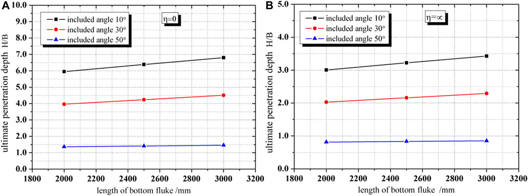
FIGURE 15. Influence of length of the bottom fluke on the ultimate penetration depth for two cases. (A) η=0; (B) η=∞.
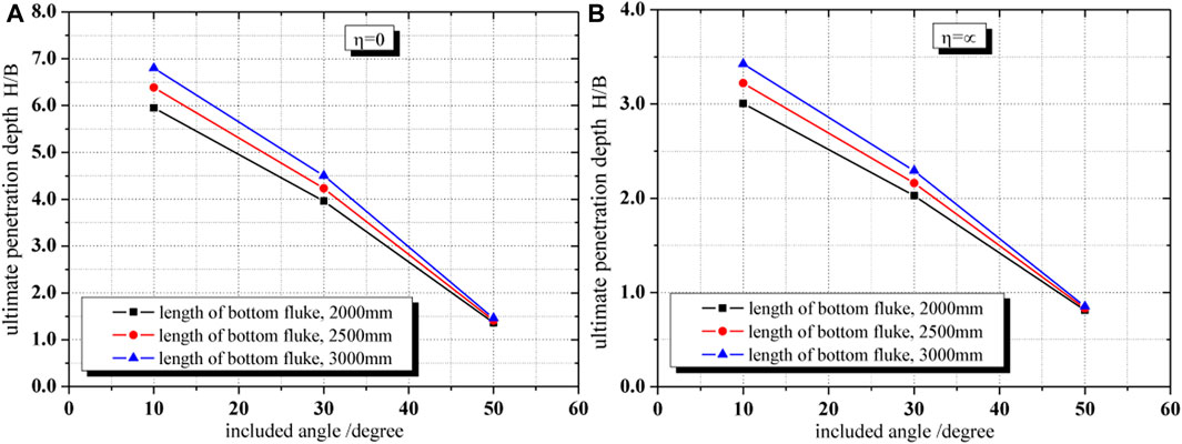
FIGURE 16. Influence of included angle on the ultimate penetration depth for two cases. (A) η=0; (B) η=∞.
3.1 Influence of the length of the bottom fluke on the ultimate penetration depth of DPVLA
As can be seen from Figure 15A, when the strength of clay at the surface of the seabed was suo = 0, i.e., η = 0, increasing the length of the bottom fluke all increased the ultimate penetration depth of DPVLAs at included angles 10°, 30°, and 50°, respectively. The ultimate penetration depth increased by about 14.3, 13.7, and 7.1% from the length of the bottom fluke 2000 mm–3000 mm when the included angles are 10°, 30°, and 50°, respectively. It was also shown that when the included angle was 10°, increasing the length of the bottom fluke can significantly increase the ultimate penetration depth of DPVLAs. However, the larger included angle, such as 50°, did not contribute to penetrating into the soil even after increasing the length of the bottom fluke of DPVLAs.
When the strength of clay was uniform, the results were as shown in Figure 15B. As can be seen from Figure 15B, the trend of influence of the length of the bottom fluke on the ultimate penetration depth of DPVLAs was similar to that in Figure 15A. However, the ultimate penetration depths of DPVLAs in soft clay with suo = 0 were greater than those of DPVLAs in soft clay with uniform strength when the included angle and the length of the bottom fluke were the same for DPVLAs.
3.2 Influence of the included angle on the ultimate penetration depth of DPVLAs
When the strength of the clay at the surface of the seabed was suo = 0, the change of the ultimate penetration depth of DPVLAs with included angles was as shown in Figure 16A. As illustrated in Figure 16A, increasing the included angle decreased the ultimate penetration depth of DPVLAs at the length of the bottom fluke 2000, 2500, and 3000 mm, respectively. The ultimate penetration depth decreased by about 77.1, 77.9, and 78.5% from the included angle 10° to 50° when the length of the bottom fluke was 2000, 2500, and 3000 mm, respectively. Figure 16A also indicated that when the included angle was larger, such as 50°, the change in the length of the bottom fluke of DPVLAs had little influence on the ultimate penetration depth, which also indicated that the included angle should be less than 50° in the process of penetrating into the soil for DPVLAs.
When the strength of clay is uniform, i.e., η = ∞, the trend of influence of the included angle on the ultimate penetration depth of DPVLAs was also the same as that in Figure 16A. In addition, Figure 16B also indicates that the ultimate penetration depths of DPVLAs in soft clay with suo = 0 were greater than those of DPVLAs in soft clay with uniform strength when the included angle and the length of the bottom fluke were the same.
4 Conclusion
The ultimate penetration depth of DPVLAs relates to the ultimate loading capacity. In this paper, based on the formula of the ultimate penetration depth of VLAs in clay proposed by Liu et al.(2010a), which was also applicable to DPVLAs in theory, the influence of the parameters on the ultimate penetration depth of DPVLAs in clay was investigated. In addition, two important parameters, θm and Ncd, in the expression of the ultimate penetration depth of DPVLAs in clay were first investigated in this paper, which contributed to obtaining the ultimate penetration depth of DPVLAs.
Through the drag penetration tests, the movement directions of the bottom fluke of DPVLAs with different lengths of the bottom fluke and different included angles were obtained. The results showed that the movement directions of the bottom fluke of DPVLA models were all parallel to the surface of fine sand, i.e., θm were equal to θi.
The bearing capacity factor, Ncd, of DPVLAs in clay is different from that of VLA, which is influenced by the length of the bottom fluke and included angle. To consider the influence of the initial orientation of DPVLAs on the ultimate penetration depth, the upper bound solutions of the ultimate pullout capacity were utilized to obtain the bearing capacity factor of DPVLAs with different included angles and different lengths of the bottom fluke in clay, which corresponded with the maximum penetration depth induced by the initial orientation of the anchor. The results showed that when the lengths of the bottom fluke of DPVLAs were the same, increasing the included angle can significantly increase the bearing capacity factors of DPVLAs. When the included angles were the same, increasing the length of the bottom fluke of DPVLAs can decrease the bearing capacity factors.
Based on the expression of the ultimate penetration depth of DPVLAs and two important parameters, θm and Ncd, the influence of the included angle and the length of the bottom fluke on the ultimate penetration depth of DPVLAs was obtained. The results showed that increasing the length of the bottom fluke of DPVLAs can increase the ultimate penetration depth when the included angles were the same not only for the clay with zero strength at the seabed but also for the clay with uniform strength. When the lengths of the bottom fluke of DPVLAs were the same, increasing the included angle can decrease the ultimate penetration depth. However, when the included angle was larger, such as 50°, the ultimate penetration depth increases little, even when increasing the length of the bottom fluke of DPVLAs compared with the smaller included angle, such as 10° and 30°.
Data availability statement
The original contributions presented in the study are included in the article/Supplementary Material. Further inquiries can be directed to the corresponding author.
Author contributions
GX: methodology, formal analysis, and writing. YC: conceptualization, methodology, investigation, and writing—review and editing. BZ: conceptualization and methodology. JL: investigation. XZ: investigation. All authors contributed to the article and approved the submitted version.
Funding
This work was financially supported by the National Natural Science Foundation of China (Grant No. 52178347) and the Natural Science Foundation of Shandong Province (Grant Nos. ZR2021ME068 and ZR2022ME165). The authors are also grateful to the undergraduates, such as Kai Jia, Junjie Yi, Shaoshuai Cui, Xurao Wang, and Jiansong Song, for their generous assistance with this work.
Conflict of interest
The authors declare that the research was conducted in the absence of any commercial or financial relationships that could be construed as a potential conflict of interest.
Publisher’s note
All claims expressed in this article are solely those of the authors and do not necessarily represent those of their affiliated organizations, or those of the publisher, the editors, and the reviewers. Any product that may be evaluated in this article, or claim that may be made by its manufacturer, is not guaranteed or endorsed by the publisher.
References
Aubeny, C. P., and Chi, C. (2010). Mechanics of drag embedment anchors in a soft seabed. J. Geotechnical Geoenvironmental Eng. 136 (1), 57–68. doi:10.1061/(asce)gt.1943-5606.0000198
Aubeny, C. P., and Murff, J. D. (2005). Suction caissons and vertical loaded anchors: Design analysis method. Texas, USA: Final Report, Department of Civil Engineering, Texas A&M University.
Bai, B., Long, F., Rao, D. Y., and Xu, T. (2017). The effect of temperature on the seepage transport of suspended particles in a porous medium. Hydrol. Process. 31 (2), 382–393. doi:10.1002/hyp.11034
Bai, B., Zhou, R., Cai, G. Q., Hu, W., and Yang, G. C. (2021). Coupled thermo-hydro-mechanical mechanism in view of the soil particle rearrangement of granular thermodynamics. Comput. Geotechnics 137 (8), 104272. doi:10.1016/j.compgeo.2021.104272
Cheng, X. L., Li, Y. F., Wang, P. G., Liu, Z. X., and Zhou, Y. D. (2019). Model tests and finite element analysis for vertically loaded anchors subjected to cyclic loads in soft clays. Comput. Geotechnics 119, 103317. doi:10.1016/j.compgeo.2019.103317ː
Det Norshke Veritas (DNV) (2000). “Design and installation of fluke anchors in clay,” in Recommended practice RP-e301dnv RP-e301. Norwegian: Det Norske Veritas.
Det Norshke Veritas (DNV) (2002). RP-E302 Design and installation of drag-in plate anchors in clay. Norwegian: Det Norske Veritas.
Liu, H. X., Liu, Y., Yang, H. T., Zhang, W., Liu, C. L., and Zhang, W. (2010a). Analytical study on the ultimate embedment depth of drag anchors. Ocean. Eng. 37, 1292–1306. doi:10.1016/j.oceaneng.2010.06.007
Liu, H. X., Zhang, W., Zhang, X. W., Liu, C. L., and Liu, C. (2010b). Experimental investigation on the penetration mechanism and kinematic behavior of drag anchors. Appl. Ocean Res. 32 (4), 434–442. doi:10.1016/j.apor.2010.09.004
Merrifield, R. S., Sloan, S. W., and Yu, H. S. (2001). Stability of plate anchors in undrained clay. Geotechnique 51 (2), 141–153. doi:10.1680/geot.51.2.141.40290
Miedema, S. A., Lagers, G. H. G., and Kerkvliet, J. (2007). An overview of drag embedded anchor holding capacity for dredging and offshore applications. Orlando, FL: WODCON.
Murff, J. D., Randolph, M. F., Elkhatib, S. H., Kolk, J. R., Ruinen, M., Strom, P. J., et al. (2005). Vertically loaded plate anchors for deepwater applications. Front. Offshore Geotechnics. doi:10.1201/noe0415390637.ch2
Naval Civil Engineering Laboratory (NCEL) (1987). “Drag embedment anchors for navy moorings,”. Techdata Sheet 83–08 R (Port Hueneme, CA: Naval Civil Engineering Laboratory NCEL.
Neubecker, S. R., and Randolph, M. F. (1995). Profile and frictional capacity of embedded anchor chains. J. Geotechnical Eng. Div. 121 (11), 797–803. doi:10.1061/(asce)0733-9410(1995)121:11(797)
Neubecker, S. R., and Randolph, M. F. (1996). The performance of drag anchor and chain systems in cohesive soil. Mar. Georesouces Geotechnol. 14, 77–96. doi:10.1080/10641199609388305
O’Neill, M. P., Bransby, M. F., and Randolph, M. F. (2003). Drag anchor fluke–soil interaction in clays. Can. Geotechnical J. 40, 78–94. doi:10.1139/t02-096
O’Neill, M. P., and Randolph, M. F. (2001). Modelling drag anchors in a drum centrifuge. Int. J. Phys. Model. Geotechnics 2, 29–41. doi:10.1680/ijpmg.2001.010203
O’Neill, M. P., Randolph, M. F., and Neubecker, S. R. (1997). “A novel procedure for testing model drag anchors,” in Proceedings of the Seventh International Offshore and Polar Engineering Conference, Honolulu, USA, May 25-30, 1997.
Qiao, D. S., and Ou, J. P. (2012). Analysis on ultimate pullout bearing capacity of drag embedment anchor under cyclic loading. J. Harbin Inst. Technol. 44 (12), 112–117. doi:10.1007/s11783-011-0280-z
Ruinen, R. M., and Degenkamp, G. (2001). “Anchor selection and installation for shallow and deepwater mooring systems,” in Proceedings of the 11th International Offshore and Polar Engineering Conference, Stavanger, Norway, June 17-22, 2001.
Ruinen, R. M., and Degenkamp, G. (2002). “Prediction of the holding capacity and trajectory of drag embedment anchors,” in Proceedings of the 34th Annual Offshore Technology Conference, OTC 14305, Houston, USA, May 6-9, 2002.
Ruinen, R. (2004). “Penetration analysis of drag embedment anchors in soft clays,” in Proceedings of the 14th International Offshore and Polar Engineering Conference ISOPE, Toulon, France, May 23-28, 2004, 531–537.
Tian, Y., Randolph, M. F., and Cassidy, M. J. (2015). Analytical solution for ultimate embedment depth and potential holding capacity of plate anchors. Géotechnique 65 (6), 517–530. doi:10.1680/geot.14.p.228
Xing, G. Q., Xuan, W., and Zhang, B. (2020). Towed embedded double-layer flat plate bearing anchor. State Intellectual Property Office of the P.R. China. ZL201910259959.x.
Xing, G. Q., Zhang, L. J., Xuan, W., Ma, J. H., Ye, X. C., Guo, S. W., et al. (2021). Capacity of double-plate vertically loaded anchor in saturated marine fine sand. Mar. Georesources Geotechnol. 40, 1302–1315. doi:10.1080/1064119X.2021.1991062
Keywords: ultimate penetration depth, double-plate vertically loaded anchor, included angle, length of a bottom fluke, soft clay
Citation: Xing G, Cao Y, Zhang B, Li J and Zhang X (2023) Influence of parameters on the ultimate penetration depth of a double-plate vertically loaded anchor in soft clay. Front. Mater. 10:1225258. doi: 10.3389/fmats.2023.1225258
Received: 19 May 2023; Accepted: 02 June 2023;
Published: 19 June 2023.
Edited by:
Xianze Cui, China Three Gorges University, ChinaCopyright © 2023 Xing, Cao, Zhang, Li and Zhang. This is an open-access article distributed under the terms of the Creative Commons Attribution License (CC BY). The use, distribution or reproduction in other forums is permitted, provided the original author(s) and the copyright owner(s) are credited and that the original publication in this journal is cited, in accordance with accepted academic practice. No use, distribution or reproduction is permitted which does not comply with these terms.
*Correspondence: Guoqi Xing, eGdxMTEwNUAxNjMuY29t