 Meihua Bian
 Jianing Peng
- Guangxi Key Laboratory of Intelligent Control and Maintenance of Power Equipment, Electric Power Research Institute of Guangxi Power Grid Co., Ltd., Nanning, China
Transmission tower structures support high-voltage power lines that carry electricity over long distance and rockfall is one of critical disasters during its safe operation. This paper presented a simplified analytical methodology for lateral dynamic responses of a transmission tower structure due to rockfall impact. At first, the lateral dynamic displacement of a lattice transmission tower structure can be represented by a second-order partial differential equation and half sine wave was used for rockfall impact. Then, the solution can be approximated by a set of specified shape functions multiplied by time-dependent generalized coordinates. And the partial differential equation is discretized into a set of single degree of freedom system. And then the shape function can be determined by solved an eigenvalue function and the fundamental frequency of a transmission tower can was derived based on the energy method and combination synthesis method. Finally, the lateral dynamic displacements can be approximately obtained. A numerical study of a transmission tower was conducted. Parametric study of the effect of impact location height, impact duration, peak impact force, as well as the distribution of cross-arms on dynamic responses were also carried out. And the results show that the discrepancy between the analytical and the computed of fundamental frequency is less than 3%, the error of dynamic displacement is within 10%, and the fundamental frequency of the structure decreases with the increase of the tower top additional mass ratio.
Introduction
Electricity plays a significant role in social development and various industries. After years of development, China has built a large-scale power transmission network that inevitably passes through regions with complex terrain (Cai and Wan, 2021). As the conQA23ng nodes between high-voltage transmission lines and the ground, transmission towers are often built on steep slopes of mountains to reduce transmission distance and power loss (Xu et al., 2022). This terrain condition increases the possibility of geological hazards. Transmission towers are susceptible to catastrophic damage caused by rockfall impacts, which can further lead to local instability (Cai et al., 2019; Xu et al., 2023) and collapse of the entire tower (Xu et al., 2021; Xue et al., 2023). Rockfall is a major disaster that seriously threatens the structural safety of transmission towers in mountainous areas.
Researchers have carried out a large number of studies on transmission towers to ensure the stable operation of the power grid (Li et al., 2022; Li, et al., 2023). In the field of finite element analysis. The study conducted by Fu and Li. (2016) investigated the dynamic response of tower systems under wind and rain loads. It was found that the average displacement amplification of the structure was 22% higher under combined wind and rain loads than when under wind loads alone. He S et al. (2019) developed a model for a three-tower, two-span tower-line system to investigate the response of the towers to wind-induced vibrations. The results indicated that the dynamic response was higher than the static response, with a stress ratio of 1.43. Morgan and Swift. (1964) identified that the behavior of the tower-line system was affected by the height of ice shedding to varying degrees. The study results revealed that ground clearance of the lower conductor of the loaded span drops below the safety limit for ice loads beyond 1 pound per foot. The study conducted by Yang and Hong. (2016) examined the nonlinear and non-elastic response of tower-line systems exposed to downburst loading. The outcomes of the investigation suggested that the load-carrying capacity curve of an individual tower was able to represent the curvature for the tower-line system. Zhou et al. (2022) performed physical model testing and numerical analysis on transmission tower landslides caused by rainfall. The study identifies the failure process and modes of these landslides. Gong and Zhi (2020) performed an analysis on the failure mode of transmission towers impacted by earthquakes. The outcomes of their study demonstrated that the failure mode of the towers, under severe seismic impacts, was in-plane global collapse as a result of local failures. According to Tian et al. (2019) a collapse analysis of transmission tower was conducted to evaluate their structural durability when exposed to varying wind angles. The results show that the bending deformation in the mid-section of the tower body was significantly better than the shear deformation, ultimately leading to the failure of its main components. The analysis of transmission tower line systems using tower and cable models is complicated and time-consuming due to the wide range of tower types. As a result, the numerical calculations required for such models can be very complex.
Buildings in mountainous areas are prone to the impact of rockfall disasters caused by earthquakes, landslides, and debris flows (Happ and Noble, 1993). In terms of the conditions for rockfall occurrence, the collapsed rock masses are mostly concentrated on slopes with a gradient greater than 32°, and after detaching from the bedrock, they fall and collide continuously with trees, buildings, and other objects, with impact velocities mostly below 20 m/s. Although the rockfall impact belongs to low to medium-speed impact, the large mass of falling rocks can still acquire significant energy during the falling process (Wyllie, 2014). In terms of the analytical solutions for displacement response under impact, Zhang et al. (2023) derived a formula to measure the largest displacement caused by kinetic energy during impact. The study found that doubling of the impactor’s mass results in a 150% increase in the maximum displacement. Wang et al. (2014) proposed two enhanced analytical techniques rooted in forced vibration theory and variable separation method to determine the natural frequency and mode shape of a uniformly cantilevered beam. Prasada Rao et al. (2004) derived a formula for predicting the natural frequency of tower-like structures based on theoretical deformation and geometric parameters. In addition, Yan et al. (2018) investigated the influence of rockfall impact angle on the impact response of reinforced concrete slabs. Their findings revealed that both the sphericity of the impacting object and the angle exert impact on the RC slabs. Prakash et al. (2021) conducted a study on the dynamic prediction of beam behavior subject to rockfall impact. The study found that the safety of the structure is primarily influenced by the impact mass. According to analysis of existing literature, there are few relevant studies on the analytical solutions of displacement response of transmission towers under rockfall impact, which is contrary to the increasing scale and potential protection needs of mountainous transmission networks.
Rockfall disasters seriously threaten the safety of mountainous transmission networks. In order to carry out impact-resistant design of structures and understand the impact of rockfall loads on transmission tower structures effectively, it is necessary to conduct in-depth research and take protective measures. This paper proposes an approximate algorithm for the fundamental frequency of tower structures based on the energy method and combination synthesis method. It derives the displacement response of iron towers under falling rock impact, verifies the proposed approximate algorithm through ABAQUS finite element numerical simulation, and parametric analysis was also carried out. This paper was organized as follows. Section 2 is devoted to theoretical derivation for the fundamental frequency and lateral dynamic displacements of the tower structure; Case study of a transmission tower was carried out in section 3; And conclusions are drawn in section 4.
Theoretical derivation
The lateral dynamic displacements of a lattice transmission tower structure can be expressed as a partial differential equation
where Y(z,t) = transverse dynamic displacement, E = Young’s modulus of material, C = tower damping intensity, m = Tower mass per unit length, Q(z,t) = impact load function. The transmission tower is a complex structure that can be reduced as a cantilever beam with a varying cross-section (Jiang et al., 2011; Wang et al., 2015). As a result, the inertia of cross Section 1 can be simply represented by
Where β = the change rate of tower section.
The continuous lateral displacement Y(z,t) is represented by the finite sum the production of shape functions and generalized coordinates (Erturk and Inman, 2011)
where φi(z) = Characteristic function of linear uniform cantilever transfer tower, yi(t) = generalized coordinates over time.
The impact of rockfall is a transient effect. And the impact of rock falling on the tower can be approximated by the impact function F (z,t) in terms of piece-wise function (Wang et al., 2014)
Where P and t0 = the half sine pulse force magnitude and duration, respectively; l0 = the height of the bottom end of the transmission tower from the impact point, δ = unit pulse function.
After substituting Eq. 3 into Eq. 1 and multiplying φj(z) on both sides of Eq. 1, then integrate each term of Eq. 1 over span L and divide by m, it yields (Wang et al., 2017):
in which
The right side of Eq. 5 can be formulated as
in which
After substituting Eq. 6 into Eq. 5, the generalized time-dependent coordinates yi can be determined
in which
The eigenfunction of a transmission tower with cross arms is given by (Erturk and Inman, 2011)
where Ai = the modal constant, L = the height of the tower, λi = the eigenvalue, and Bi is given by
The eigenvalue of a system can be determined by solving the characteristic equations (Erturk and Inman, 2011)
Once the eigenvalues solved in Eq. 12 and then substitute Eqs 8–10 into Eq. 3, the lateral dynamic displacements of a transmission tower equipped with cross arms subjected to rockfall impact can be determined.
The fundamental frequency of the vibration of a transmission tower structure using energy method is given by (Gu and Yin, 1983)
where xf (z), xs (z) = displacement due to bending and shear deformation of the structure, respectively; G, E = shear modulus and modulus of elasticity of the structure, respectively; Wi = concentrated mass load, k' = 5/6 (rectangular section), G = 3E/8, and cross-sectional area A = A0(1+βz/L).
Since the variation of the cross-section and additional cross arms of the transmission tower, it is difficult to calculate the fundamental frequency. Herein the combined synthesis method is used to calculate the simplified calculation of multiple subsystems. According to the combination synthesis method, its fundamental frequency can be approximated by a combination of the fundamental frequencies of subsystem (Gu and Yin, 1983).
Where
The selected deflection function must satisfy the geometric boundary conditions. Since a transmission tower structure can be idealized as a cantilever beam with a stationary end and a free end, xf represents the deflection due to bending and it could be chosen as follows (Erturk and Inman, 2011)
Cf is unknown coefficient. And xs represents the displacements due to shear deformation and it could be taken the first two Fourier steps as follows Cf is unknown coefficient. And xs represents the displacements due to shear deformation and it could be taken the first two Fourier steps as follows
Cs is unknown coefficient.
By substituting Eq. 19 into Eqs 15, 17 and substituting Eq. 20 into Eqs 16, 18, we obtain:
And finally, the fundamental frequency of a transmission tower structure can be determined by substituting Eqs 21–24 into Eq. 14
Case study
FEM of a transmission tower
The transmission tower structure under consideration has a height of 36 m, as shown in Figure 1. The tower’s Finite Element Model (FEM) was created by ABAQUS software, and B31 element was adopted for beam members. The cross-section of beam member is angle steel and the tower base dimensions are 6.5 m × 6.5 m. The main members’ inclination angle is 85°.
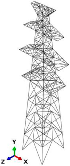
FIGURE 1. FEM by ABAQUS.
The tower body composes of the primary, diagonal, and auxiliary members, all constructed of Q235 steel, and the physical parameters are: mass density of 7850 kg/m³, modulus elasticity 206 × 1011 Pa, and Poisson’s ratio 0.3. The beam members are all made of “L" shaped angle steel, with main member sizes (mm × mm) including 160 × 12, 140 × 12, 140 × 10, 125 × 8, 100 × 8, 90 × 7, 80 × 6, 75 × 6, 75 × 5, and 70 × 5. The Johnson-Cook constitutive model was adopted as the dynamic constitutive model, which is mathematically expressed as
where U, V, n, W and m are material parameters summarized in Table 1;

TABLE 1. Parameters in steel J-C constitutive relationship of Q235B.
For simplicity, spherical models of falling rocks have been widely used in existing literature (He B et al., 2019; Xie et al., 2020). In this paper, a spherical model with a diameter of 1 m was used to represent falling rocks. The rock is assumed to be a sphere in order to simplify the model, and the impact between the rock and the transmission tower is modeled as a face-to-face contact. The contact area of the transmission tower is angle steel member and falling rock sphere can be considered as a target contact surface. The base of the transmission tower is assumed fixed, and the members are rigidly connected. In this study, the rock sphere mesh and the beam element were set to 100 mm. The falling rock properties were defined as follows: density of 2500 kg/m³, elasticity of 20GPa, and Poisson’s ratio of 0.2 (Lan et al., 2007). Rockfall is usually quite common in mountain areas with slopes greater than 32° and impact velocities are mostly under 20 m/s. Herein, rockfall with impact velocities of 10 m/s was used (Wyllie, 2014). Since the rotational energy of the falling rock accounts for only 10% of the translational energy during impact, the effect of angular velocity is ignored during the simulation (Chau et al., 2002). According to existing literature, the duration of impact action due to falling stones on prestressed concrete bridges is about 0.1–0.2s (Zhang et al., 2022), and on reinforced concrete columns is about 0.1–0.2s (Xie et al., 2020). The impact time of stone ball on a steel plate as well as iron ball on concrete slab is about 0.1–0.3s (Yu et al., 2018), and on steel pipe is about 0.4s (Chen et al., 2020). Herein, the impact action time is set as 0.2s.
Results and discussion
Figure 2 illustrates the first six natural frequencies and corresponding modal shapes obtained through modal analysis of the transmission tower. It can be seen that the first two natural frequencies are bending along the Y direction, and X direction respectively. The first-order natural frequency, calculated using Eq. 14, is 1.9801 Hz, and it is quite close to the results of 1.9375 Hz by the model analysis in ABAQUS, around 2.2% error.
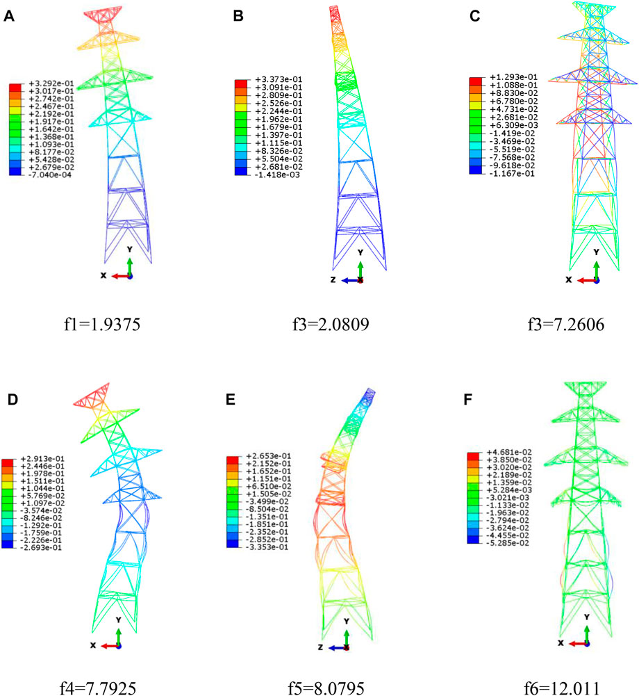
FIGURE 2. The first six natural frquencies and modes of transmission tower.
Figure 3 shows the time history of dynamic displacement on the top of the tower after the impact. After impact, the tower structure oscillated back and forth around the central point until it came to rest. The theoretical values are the results calculated based on the Eq. 3, and the simulated values are computed by the finite element software. Figure 3A illustrates the maximum dynamic displacement on the top of the tower, which is 4.46 mm. From Eq. 3, the maximum displacement response is 4.07 mm, with error of 8.7%. This is far less than the specification that the deflection curve of different types of towers under load should not exceed 2L/1000-7L/1000 (GB 50545-2010, 2020). According to Figures 3B, C, where the transmission tower is at heights of 31 m and 26 m respectively, the maximum theoretical values are 3.23 mm and 1.77 mm. The corresponding finite-element analysis results show a small discrepancy, with errors of 9.4% and 7.8% respectively.
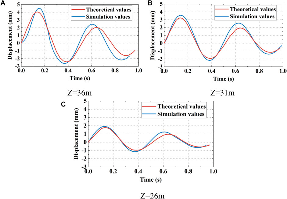
FIGURE 3. Diasplacement resposes at different positions: (A) Z = 36 m; (B) Z = 31 m; (C) Z = 26 m.
Parametric analysis
Parametric analysis was carried out to examine the effect of the impact of rockfall on the dynamic displacement response of the transmission tower. A set of variable parameters based on the characteristics of rockfall in mountainous areas, such as impact height, impact duration as well as peak impact force, as summarized in Table 2 (Xie et al., 2020; Prakash et al., 2021).
The transmission tower under consideration has four cross-arm, and it can be simplified as a cantilever beam structure, and the influence of the number of cross-arms on the transmission tower was also considered. To improve the accuracy of the formula, the cross-arm part was simplified as an additional mass in theoretical analysis.

TABLE 2. The effect factors during rockfall impact.
Impact height
Figure 4A shows the results of calculating the displacement response at the top of the transmission tower when the impact duration lasts for 0.02 s and the height of falling rocks are 3 m, 5 m, and 9 m respectively, with the peak impact force being 650 kN and other parameters remaining constant.
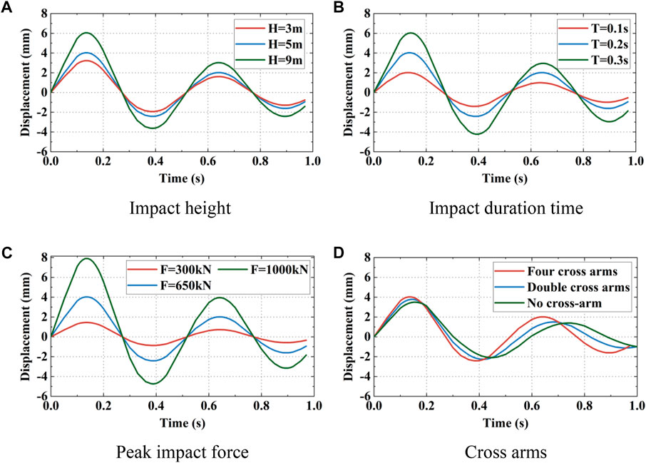
FIGURE 4. Displacement responses on the top tower: (A) impact height; (B) impact durction time; (C) peak impact force; (D) cross arms.
The maximum displacement of the transmission tower’s top is 3.22 mm at an impact height of 3 m, for 5 m, the maximum displacement is 4.03 mm, and for 9 m, the maximum displacement is 6.05 mm. Increasing the impact height results in non-linearly increasing displacement of the top of the tower. This arises because a higher impact position transfers greater kinetic energy to the transmission tower from the falling rocks.
Impact duration time
The falling rock impact height was set to 5 m, and the peak impact force was set at 650 kN. To examine the impact of the falling rock on tower top displacement, varying falling rock impact times of 0.01 s, 0.02 s, and 0.03 s were explored while all other parameters were kept constant.
The findings illustrated in Figure 4B demonstrated that as the duration of impact increases, the maximum displacement of the top of the transmission tower also increases. The maximum displacement when the impact duration time is 0.01 s is 2.01 mm, 4.03 mm when the time is 0.02 s, and 6.04 mm when it is 0.03 s. The dynamic displacement of the top tower considerably increases as the falling rock impact time increases, primarily due to the greater kinetic energy transferred from the falling rock to the transmission tower.
Peak impact force
It is assumed that the impact height is 5 m and the impact lasts for 0.2 s, the effect of peak impact force was investigated. The peak impact forces of falling rocks are 300 kN, 650 kN, and 1000 kN respectively, and the dynamic displacement response on the top transmission tower is shown in Figure 4C.
The peak impact force of rockfall has great effect on the transmission tower. The maximum displacement on the top transmission tower was measured for various peak impact forces, resulting in a displacement of 1.45 mm for 300 kN, 4.03 mm for 650 kN, and 7.91 mm for 1000 kN. The impact force of falling rocks has a significant effect on dynamic displacements of the tower’s top structure. This effect is evident and implies that the greater the impact force, the larger the displacement.
Number of cross arms
The cross arm is considered as an additional mass, and in the calculation formula of the fundamental frequency, the distributed mass and the additional mass of the tower body are both considered. The effect of the number of cross arms was also investigated. Herein four cross arms double cross arms are compared with no cross arms situation. The results of the dynamic displacement response on the top tower is shown in Figure 4D.
The maximum displacements on the top tower with three cases of cross arms conditions are 4.03 mm, 3.77 mm, and 3.49 mm, respectively, and their self-oscillation frequencies are 1.98 Hz, 2.03 Hz and 2.07 Hz respectively. The cross arms can be considered as additional mass attached on the different position of the tower. It is evident that as the number of cross arms, i.e., the additional mass increased, the dynamic displacement on the top tower also increases while the frequency decreases.
The results of the parametric study showed that the displacement of the transmission tower is significantly affected by both the impact height and the peak impact force of falling rocks. Unfortunately, the design codes for transmission lines do not provide any specific measures for preventing and controlling the impact of falling rocks on transmission towers. It is recommended that designers should pay much attention to areas prone to rockfall disasters and exclude rocks with excessive height and potential for producing significant impact forces to avoid hazards to transmission towers.
Conclusion
In this paper, we present an algorithm that estimates the fundamental frequency of tower structures. The algorithm combines the energy method and the combination synthesis method to provide an accurate approximation. The bending and shear deformations of transmission towers, as well as the effects of the distribution and variable cross-section characteristics of cross-arms near the tower top are also under consideration. The displacement response of the tower under rockfall impact is derived. The parametric analysis was also carried out. The following conclusions are drawn.
(1) The peak impact force has a larger impact on the displacement response of transmission towers when compared to the impact action time, impact height, and number of cross-arms.
(2) With the increase of the number of cross-arms on the top tower, which is the additional mass ratio, the displacement of the top tower will increase and the vibration fundamental frequency of the structure will decrease.
(3) The comparison verification by finite element example shows that the errors of the theoretical data of displacement response are within 10%, and the errors of fundamental frequency are only 2.2%.
The algorithm proposed in this article is not only applicable for the calculation of the fundamental frequency and displacement response of transmission towers, but also suitable for other tower-like structures. However, the article did not take into account the cable effect on transmission towers. The dynamic displacement responses of tower-like structures under cables constraint conditions needs further research.
Data availability statement
The raw data supporting the conclusion of this article will be made available by the authors, without undue reservation.
Author contributions
Conceptualization, software, validation, writing—original draft, MB; methodology, JP and SQ; investigation, XZ; data curation, JL. All authors contributed to the article and approved the submitted version.
Funding
The authors declare that this study received funding from Electric Power Research Institute of Guangxi Power Grid Co. Ltd. of China (Grant number: GXKJXM20210299). The funder was not involved in the study design, collection, analysis, interpretation of data, the writing of this article, or the decision to submit it for publication.
Conflict of interest
Authors MB, JP, SQ, XZ, and JL were employed by the company Electric Power Research Institute of Guangxi Power Grid Co., Ltd.
Publisher’s note
All claims expressed in this article are solely those of the authors and do not necessarily represent those of their affiliated organizations, or those of the publisher, the editors and the reviewers. Any product that may be evaluated in this article, or claim that may be made by its manufacturer, is not guaranteed or endorsed by the publisher.
References
Cai, Y., and Wan, J. (2021). Wind-resistant capacity modeling for electric transmission line towers using kriging surrogates and its application to structural fragility. Appl. Sci. 11 (11), 4714. doi:10.3390/app11114714
Cai, Y., Xie, Q., Xue, S., Hu, L., and Kareem, A. (2019). Fragility modelling framework for transmission line towers under winds. Eng. Struct. 191, 686–697. doi:10.1016/j.engstruct.2019.04.096
Chau, K. T., Wong, R. H. C., and Wu, J. J. (2002). Coefficient of restitution and rotational motions of rockfall impacts. Int. J. Rock Mech. Min. Sci. 39 (1), 69–77. doi:10.1016/S1365-1609(02)00016-3
Chen, Z., Wang, J., Chen, J., GangaRao, H., Liang, R., and Liu, W. (2020). Responses of concrete-filled FRP tubular and concrete-filled FRP-steel double skin tubular columns under horizontal impact. Thin-Walled Struct. 155, 106941. doi:10.1016/j.tws.2020.106941
Fu, X., and Li, H. N. (2016). Dynamic analysis of transmission tower-line system subjected to wind and rain loads. J. Wind Eng. industrial aerodynamics 157, 95–103. doi:10.1016/j.jweia.2016.08.010
GB 50545-2010 (2010). Technical code of designing 110∼ 500kV overhead transmission line. National Standards of People’s Republic of China.
Gong, J., and Zhi, X. (2020). Earthquake failure mode and collapse fragility of a 1000 kV outgoing line frame considering interactions in the tower line system. Eng. Struct. 27, 626–638. doi:10.1016/j.istruc.2020.06.018
Happ, E. L., and Noble, M. A. (1993). An engineering rock classification to evaluate seismic rock-fall susceptibility and its application to the Wasatch Front. Environ. Eng. Geoscience 30 (3), 293–319. doi:10.2113/gseegeosci.xxx.3.293
He, B., Zhao, M., Feng, W., Xiu, Y., Wang, Y., Feng, L., et al. (2019). A method for analyzing stability of tower-line system under strong winds. Adv. Eng. Softw. 127, 1–7. doi:10.1016/j.advengsoft.2018.10.004
He S, S., Yan, S., Deng, Y., and Liu, W. (2019). Impact protection of bridge piers against rockfall. Bull. Eng. Geol. Environ. 78, 2671–2680. doi:10.1007/s10064-018-1250-5
Jiang, W. Q., Wang, Z. Q., McClure, G., Wang, G. L., and Geng, J. D. (2011). Accurate modeling of joint effects in lattice transmission towers. Eng. Struct. 33 (5), 1817–1827. doi:10.1016/j.engstruct.2011.02.022
Lan, H., Martin, C. D., and Lim, C. H. (2007). RockFall analyst: A gis extension for three-dimensional and spatially distributed rockfall hazard modeling. Comput. Geosciences 33 (2), 262–279. doi:10.1016/j.cageo.2006.05.013
Li, J. X., Cheng, J. P., Zhang, C., Qu, C. X., Zhang, X. H., and Jiang, W. Q. (2023). Seismic response study of a steel lattice transmission tower considering the hysteresis characteristics of bolt joint slippage. Eng. Struct. 281, 115754. doi:10.1016/j.engstruct.2023.115754
Li, J. X., Zhang, X. H., and McClure, G. (2022). Numerical and full-scale test case studies on post-elastic performance of transmission towers. Eng. Struct. 259, 114133. doi:10.1016/j.engstruct.2022.114133
Morgan, V. T., and Swift, D. A. (1964). Jump height of overhead-line conductors after the sudden release of ice loads. Proc. Institution Electr. Eng. 111 (10), 1736–1746. doi:10.1049/piee.1964.0285
Prakash, A., Monika, A. P., and Anandavalli, N. (2021). Behaviour of steel-concrete composite (SCC) girder under impact due to rock fall. J. Constr. Steel Res. 177, 106474. doi:10.1016/j.jcsr.2020.106474
Prasada Rao, N., Mohan, S. J., and Lakshmanan, N. (2004). A semi empirical approach for estimating displacements and fundamental frequency of transmission line towers. Int. J. Struct. Stab. Dyn. 4 (02), 181–195. doi:10.1142/S0219455404001185
Tian, L., Pan, H., Qiu, C., Ma, R., and Yu, Q. (2019). Wind-induced collapse analysis of long-span transmission tower–line system considering the member buckling effect. Adv. Struct. Eng. 22 (1), 30–41. doi:10.1177/1369433218774961
Wang, J., GangaRao, H., Liang, R., and Liu, W. (2017). Experimental and analytical responses of hollow and concrete-filled GFRP tube columns under impact. J. Compos. Constr. 21 (4), 04017013. doi:10.1061/(ASCE)CC.1943-5614.0000793
Wang, J., Liu, W., Wang, L., and Han, X. (2015). Estimation of main cable tension force of suspension bridges based on ambient vibration frequency measurements. Struct. Eng. Mech. 56 (6), 939–957. doi:10.12989/sem.2015.56.6.939
Wang, H. J., Meng, Q. F., and Feng, W. W. (2014). Discussion of the improved methods for analyzing a cantilever beam carrying a tip-mass under base excitation. Shock Vib. 2014. doi:10.1155/2014/981053
Wang, Y., Qian, X., Liew, J. R., and Zhang, M. H. (2014). Experimental behavior of cement filled pipe-in-pipe composite structures under transverse impact. Int. J. Impact Eng. 72, 1–16. doi:10.1016/j.ijimpeng.2014.05.004
Xie, R., Fan, W., Liu, B., and Shen, D. (2020). Dynamic behavior and vulnerability analysis of bridge columns with different cross-sectional shapes under rockfall impacts. Structures 26, 471–486. doi:10.1016/j.istruc.2020.04.042
Xu, J., He, S., Cao, X., Yao, L., Liu, X., and Yan, X. (2022). Analytical and numerical analysis of angle steel joints for conductors in lattice transmission towers. Case Stud. Constr. Mater. 17, e01592. doi:10.1016/j.cscm.2022.e01592
Xu, L. Y., Chen, W. Y., Cai, F., Song, Z., Pan, J. M., and Chen, G. X. (2023). Response of soil–pile–superstructure–quay wall system to lateral displacement under horizontal and vertical earthquake excitations. Bull. Earthq. Eng. 21 (2), 1173–1202. doi:10.1007/s10518-022-01572-z
Xu, L. Y., Song, C. X., Chen, W. Y., Cai, F., Li, Y. Y., and Chen, G. X. (2021). Liquefaction-induced settlement of the pile group under vertical and horizontal ground motions. Soil Dyn. Earthq. Eng. 144, 106709. doi:10.1016/j.soildyn.2021.106709
Xue, Y. Y., Wang, X. G., and Cai, F. (2023). Effect of inclined pile on seismic response of bridge abutments undergoing liquefaction—induced lateral displacement: Case study of nishikawa bridge in the 2011 great east Japan earthquake. Front. Mater. 10, 1185210. doi:10.3389/fmats.2023.1185210
Yan, P., Zhang, J., Fang, Q., and Zhang, Y. (2018). Numerical simulation of the effects of falling rock’s shape and impact pose on impact force and response of RC slabs. Constr. Build. Mater. 160, 497–504. doi:10.1016/j.conbuildmat.2017.11.087
Yang, S. C., and Hong, H. P. (2016). Nonlinear inelastic responses of transmission tower-line system under downburst wind. Eng. Struct. 123, 490–500. doi:10.1016/j.engstruct.2016.05.047
Yu, B., Yi, W., and Zhao, H. (2018). Experimental study on the maximum impact force by rock fall. Landslides 15, 233–242. doi:10.1007/s10346-017-0876-x
Zhang, J., Wang, R., Han, W., and Bao, H. (2022). A comprehensive approach for bridge performance evaluation under rockfall impact integrated with geological hazard analysis. Eng. Fail. Anal. 141, 106668. doi:10.1016/j.engfailanal.2022.106668
Zhang, J. Z., Li, G. Q., Sun, Y. Z., Sun, J., Yu, Z. W., and Feng, R. (2023). Maximum displacement prediction of composite floor system under falling impact. Eng. Struct. 275, 115326. doi:10.1016/j.engstruct.2022.115326
Zhou, Y., Sheng, Q., Chen, J., Li, N., Fu, X., and Zhou, Y. (2022). The failure mode of transmission tower foundation on the landslide under heavy rainfall: A case study on a 500-kV transmission tower foundation on the yanzi landslide in barong, China. Bull. Eng. Geol. Environ. 81 (3), 125. doi:10.1007/s10064-022-02628-9
Keywords: transmission tower, rockfall impact, fundamental frequency, dynamic displacement response, modal analysis
Citation: Bian M, Peng J, Qin S, Zhang X and Li J (2023) A simplified analytical method for lateral dynamic responses of a transmission tower due to rockfall impact. Front. Mater. 10:1229327. doi: 10.3389/fmats.2023.1229327
Received: 26 May 2023; Accepted: 12 July 2023;
Published: 03 August 2023.
Edited by:
Chun-Xu Qu, Dalian University of Technology, ChinaCopyright © 2023 Bian, Peng, Qin, Zhang and Li. This is an open-access article distributed under the terms of the Creative Commons Attribution License (CC BY). The use, distribution or reproduction in other forums is permitted, provided the original author(s) and the copyright owner(s) are credited and that the original publication in this journal is cited, in accordance with accepted academic practice. No use, distribution or reproduction is permitted which does not comply with these terms.
*Correspondence: Meihua Bian, Ymlhbl9taC5zeUBneC5jc2cuY24=, Z3hkd3htQDEyNi5jb20=