 Marek Šafář1
 Jan Valíček1,2,3
 Marta Harničárová1,2,3*Michal Šajgalík3Hakan Tozan4Milena Kušnerová2Mário Drbúl3
 Milan Kadnár1,5Andrej Czán3
- 1Faculty of Engineering, Institute of Electrical Engineering, Automation, Informatics and Physics, Slovak University of Agriculture in Nitra, Nitra, Slovakia
- 2Department of Mechanical Engineering, Faculty of Technology, Institute of Technology and Business in České Budějovice, České Budějovice, Czechia
- 3Department of Machining and Manufacturing Technology, Faculty of Mechanical Engineering, University of Zilina, Žilina, Slovakia
- 4College of Engineering and Technology, American University of the Middle East, Egaila Kuwait City, Kuwait
- 5Faculty of Engineering, Institute of Design and Engineering Technologies, Slovak University of Agriculture in Nitra, Nitra, Slovakia
Residual stresses are defined as the stresses that occur in the material without the application of an external load. Their occurrence is related to the technology of production and treatment of the material. This article proposes the identification of residual stresses in a steel material for bearing production, specifically 100Cr6 (1.3505) material. The identification consists in measuring the material by X-ray diffraction method, for which the Proto iXRD mobile diffractometer was chosen. The first measurement was carried out on turned bearing rings and a subsequent second measurement was carried out on the same rings after heat treatment, namely quenching and tempering. This article also proposes a measurement methodology for the bearing rings, where each ring is measured in 6 positions rotated 60° with respect to each other. The measurement results are compared with the individual manufacturing operations, i.e. turning and heat treatment. The results clearly show the expected increase in residual stresses after turning and subsequent decrease after heat treatment. The technological parameters of turning fundamentally influence the residual stresses and thus also affect the quality of the product in subsequent production operations.
1 Introduction
The issue of residual stresses generated as a result of machining processes is often investigated and discussed, especially in mechanical engineering. Nowadays, there is a growing interest in a deeper understanding of residual stresses that significantly affect the mechanical properties of the material and its structure. In the field of stress analysis, many questions remain unanswered. Therefore, in current engineering practice, residual stresses are considered fundamental parameters of the actual surface state of extremely stressed materials. Residual stresses arise as a result of the action of almost all technological processes in the deformation of the material, i.e., heat treatment, machining or processing that changes the shape of the product or the properties of the material (Huang et al., 2018; Soori and Arezoo, 2022). Therefore, they have a decisive influence on the fracture strength of the material, the fatigue behaviour of mechanical parts of machines, or the resistance to corrosion. These stresses are the result of many influences and may be present in the raw material introduced during production or may originate from operational use. They may be large enough to cause ductility and plastic deformation in certain locations in the material, both at the microscopic and macroscopic levels. As a result, higher values of residual stresses can seriously affect the performance of the components or cause dangerous cracks to appear under extreme loading of the component.
The residual stresses in the surface and subsurface layer of the material depend on a number of structural, mechanical, and chemical properties of the machined material, as well as its temperature distribution. The nature of the residual stress distribution has a particular influence on its operational properties. Compressive stresses increase the fatigue limit and improve the wear resistance of the surface; tensile stresses, on the other hand, decrease the fatigue limit and facilitate the disruption of friction surfaces. By intelligent use of residual stresses, the static behaviour of loaded brittle materials can be improved (Pape et al., 2019; Li et al., 2022). The study of the influence of the working conditions on the type and magnitude of residual stresses is, therefore, one of the bases needed for optimising the machining process in terms of the quality of the workpiece in relation to its functional use (Liu et al., 2004; Pape et al., 2017).
Especially after quenching, the determination of residual stresses shows a significant influence on technological operations such as face and outer diameter grinding, hole and raceway grinding, and also the influence on further finishing operations. The identification of the residual stresses, especially their limit values in the context of destructive tests, makes it possible to predict the subsequent behaviour of the material during grinding and various finishing operations.
The determination of residual stresses generated after downstream technological operations is also very important for many reasons. Especially in finishing operations, a frequent problem is the generation of unwanted stresses in the material, which makes it difficult, for example, to comply with the prescribed drawing tolerances.
The influence of production methods in relation to functional use can be expressed in terms of surface integrity. Surface integrity includes not only the applied technological methods and their influence on the properties of the machined surface in relation to the functional requirements but also describes the conditions under which the functional surface was created and the subsequent changes caused by the technological operation used (Javadi et al., 2019; Jouini et al., 2020; Pape et al., 2020). These changes are put in relation to the functional requirements of the surface. In recent years, there has been a new urgency to understand and manage the relationship between the surface qualities produced by different machining methods and the functional requirements of the surface, as higher functional surface requirements necessarily translate into increased production costs. In particular, the relationship between the surface quality of new materials and the functional requirements of major surfaces must be continually investigated and refined (Tong et al., 2012; Hua et al., 2019; Wang et al., 2020). According to the literature search, there is no predictive model with general validity available. In fact, the complexity of the mechanism of residual stress generation impedes the development of a model based on a physical description (Xueping et al., 2009; Ma et al., 2018; Sjöström et al., 2022).
Verified measurement procedures for estimating residual stresses are very important. There is a great deal of experimental studies in the literature related to residual stresses (Zhou et al., 2015). Generally, experimental techniques have many limitations, such as laboriousness, time-consumingness, a limited range of sizes and shapes that can be measured, as well as a lack of accuracy dependent on the skill of the operators as well as the capabilities of the machine. Therefore, the development of computational means in the second half of the 20th century led to the development of computational methods aimed at algorithmizing engineering tasks through differential methods, which include finite element methods and integral methods (Maroju and Pasam, 2019; Peng et al., 2021; Ahmadpoor et al., 2022). The paper (Elsheikh et al., 2021) provides a detailed review on residual stresses induced by turning on machined components. In this review, the authors explore the different methods of measuring residual stress, the effects of cutting parameters such as cutting speed, depth of cut, and feed rate, the configuration of cutting tools, cooling conditions and wear conditions, as well as the creation of residual stress in hard-to-machine materials (Outeiro et al., 2008; Peng et al., 2020; Biasibetti et al., 2021; Butola et al., 2021; Zheng et al., 2022).
There can be benefits and drawbacks associated with residual stresses in a variety of applications. Bearings are especially susceptible to tensile stresses, which promote crack propagation and diminish fatigue life. Contact fatigue is a common occurrence in bearings (Bedekar et al., 2019). There is a central role for residual stress in the lifetime of a bearing, but this can be difficult to manipulate precisely without reliable data.
For the above reasons, the aim of the presented publication is to develop a simple proposal for a flexible and reliable method of identifying residual stresses. The purpose is their prediction that can be quickly applied in practice based on measurements, evaluation of the measurement results, and their analysis and adequate interpretation in rolling bearings.
2 Experimental part
The rings were first turned, then measured and then heat treated (clouded) and measured again. The selected bearings are supplied by KOYO to the customer MITEC, who then installs them in gearboxes to change the angular velocity and torque in certain types of cars (Land Rover, Jaguar).
2.1 Bearing manufacturing technology and quality standards
The bearings were manufactured according to the commonly used ISO-492-2002 standard. This international standard specifies tolerances for the limiting dimensions and running accuracy of radial roller bearings specified in ISO 15, ISO 355, and ISO 8443.
The requirements for the quality of the final surface depend mainly on the material from which the bearings are made. In particular, it is about the possible surface defects and the depth of the decarburised layer. The surface of the rolled tubes must be free from surface defects such as scratches and grooves, cracks or scales and must not be burnt or heated (etching tests are carried out after grinding to identify burnt or heated material). If these defects were to occur, they would have to be removed uneconomically by machining an increased material allowance or discarded outright as non-conforming pieces.
Decarburisation (up to a certain depth of material) occurs during manufacturing operations (heating, rolling, soft annealing) in which a protective atmosphere is not provided. Quality removal of the decarburised layer is only achieved by chip machining (turning, grinding).
Other specific requirements for bearing ring surfaces are their roughness, roundness, and waviness.
Lower surface roughness is desirable on orbits because it causes less wear, greater durability, and lower noise. While the roughness on non-functional surfaces is Ra = 0.5 µm, on functional surfaces (loaded by rolling element circulation) a lower roughness is required as standard, Ra = 0.15 µm or Ra = 0.12 µm.
The roundness of the functional and non-functional surfaces of the bearing rings is specified according to the standard (ČSN ISO 1132). The prescribed roundness on the functional raceway surfaces significantly influences the bearing running quality (inner diameter at the outer ring, outer diameter at the inner ring, and at the outer diameter of the rolling element). From the point of view of correct bearing mounting, non-functional roundness (on the outer diameter of the outer ring and on the inner diameter of the inner ring) is allowed to be up to an order of magnitude greater, as these surfaces do not affect the bearing running. The roundness of the orbit can be viewed as a profile of true shape moving around an ideal circle in positive and negative deviations oscillating regularly in “waves”. In practice, low wave count deviations are evaluated when the number of waves is less than 14 per revolution. For the presented bearing rings, the roundness is in the order of um, or a maximum deviation of 2 um per functional area.
Waviness, like roundness, is evaluated in relation to an ideal circle, with the number of deviating “waves” typically greater than 14 per revolution. The waviness is particularly affected by finishing operations (grinding, superfinishing). The waviness is assessed from the same recorded signal as the roundness, filtering out only the frequencies included in the roundness. The corrugation of the presented bearing rings was given by the internal standard of JTEKT Bearing in Olomouc (after renaming the former KOYO company), which is specified as different from the corrugations of rolling elements to avoid undesirable resonance phenomena.
Stabilizing the dimensional accuracy of bearing rings means, in particular, stabilizing their manufacturing process. It is necessary to have real-time information about the manufacturing process based on data obtained from sub-processes and to work with “post-process” gauges, i.e., gauges designed for the output of sub-operations. This data is crucial to send a signal to the machine tool (lathe or grinder) to make corrections. In the case of turning and grinding, post-process gauges can be effectively used to measure geometric dimensions and geometric tolerances quickly. Grinding is a more efficient manufacturing operation than turning, and cycle times are shorter. Therefore, there is no time for measuring pieces at the output in engineering practice. However, modern grinding machines have electronic speed control, they are very reliable and precise production machines that routinely achieve high accuracy (up to 0.001 mm) and generate surface roughness up to 0.025 μm when grinding. When the requirement for regular maintenance and adjustment by trained operators is met, the demands for dimensional accuracy can be fully accepted.
Heat treatment (quenching) is such a variable process that stabilization of dimensional accuracy is not assured by, for example, metallographic tests, cut-outs or hardness measurements for each hardened production batch. Again, this must be based on the collection and interpretation of data that can be used to predict how well a given batch will be hardened. A factor significantly affecting the production process is the batch of material, which may vary slightly in chemical composition. This is where the measurement of internal stresses in the material by non-destructive testing (X-ray or ultrasonic) is helpful. Tempering then reduces the stresses and brittleness of the steel after pre-hardening and ensures dimensional stabilisation.
Bearings are an essential component of various machines, and the precision of their dimensions and running accuracy is of paramount importance when it comes to their production and application. Stabilizing the dimensional accuracy of bearing rings means, in particular, stabilizing their manufacturing process. It is necessary to have real-time information about the manufacturing process based on data obtained from sub-processes and to work with “post-process” gauges, i.e., gauges designed for the output of sub-operations. This data is crucial to send a signal to the machine tool (lathe or grinder) to make corrections. In the case of turning and grinding, post-process gauges can be effectively used to measure geometric dimensions and geometric tolerances quickly. Grinding is a more efficient manufacturing operation than turning, and cycle times are shorter. Therefore, there is no time for measuring pieces at the output in engineering practice. However, modern grinding machines have electronic speed control, they are very reliable and precise production machines that routinely achieve high accuracy (up to 0.001 mm) and generate surface roughness up to 0.025 μm when grinding. When the requirement for regular maintenance and adjustment by trained operators is met, the demands for dimensional accuracy can be fully accepted.
Heat treatment (quenching) is such a variable process that stabilization of dimensional accuracy is not assured by, for example, metallographic tests, cut-outs or hardness measurements for each hardened production batch. Again, this must be based on the collection and interpretation of data that can be used to predict how well a given batch will be hardened. A factor significantly affecting the production process is the batch of material, which may vary slightly in chemical composition. This is where the measurement of internal stresses in the material by non-destructive testing (X-ray or ultrasonic) is helpful. Tempering then reduces the stresses and brittleness of the steel after pre-hardening and ensures dimensional stabilisation.
The manufacturing quality of bearing rings in terms of their surface roughness, roundness, parallelism, and various geometric tolerances is now very well studied. The presented publication has new objectives: to offer an alternative to destructive testing of bearing rings, to pave the way for the prediction of residual stresses in materials, to communicate clearly and unambiguously with suppliers of semi-finished products (especially tubes and rods) regarding material quality. In fact, standard metallographic tests (especially sections, hardness measurements, etc.) are laboratory tests with no predictive value about the internal stresses in the material. Internal stresses are present in all manufacturing operations because each machining operation introduces more and more stresses into the material, starting with turning, hardening, tempering, grinding, superfinishing and assembly. It can, therefore, be assumed that internal stresses have a primary effect on the resulting bearing life, if extreme, even a well machined surface finish will not increase the life of such a bearing ring to the desired level.
2.2 Applied material
The material used was 100Cr6 steel type 1.3505 (Table 1), which is one of the most commonly used grades of bearing steels from the group of quenchable bearing steels. In terms of chemical composition, it is a high-carbon, low-alloy steel with chromium addition, mainly used in the production of rolling bearings. Its dominant mechanical properties are high hardness, wear resistance, and long service life. As this steel achieves Rc values of 60–67 at room temperature (Rockwell hardness), it has, in particular, high resistance to pressure and abrasion.
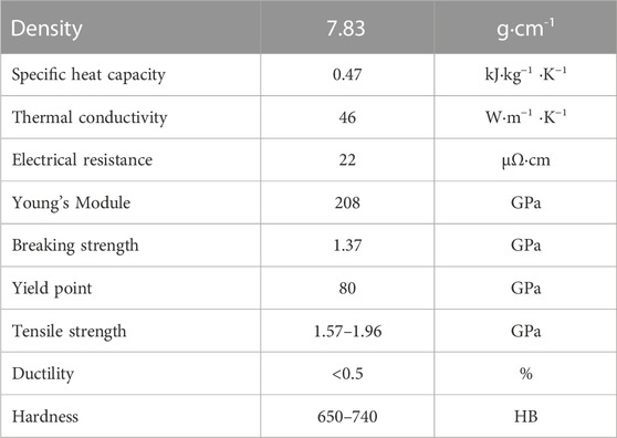
TABLE 1. Physical and mechanical properties of 100Cr6 steel after quenching and tempering.
Due to the excellent physical and mechanical properties of this steel, its applications in technical practice are wide; they are used mainly in abrasion-stressed automotive components (brakes, steering, line shaft), as well as in agitators, sliders, quick couplings, machine tools, locking mechanisms, conveyor belts, skates, springs, pumps, measuring instruments, valves, etc.
2.3 Method and measuring instrument used for measuring residual stresses
The basic principle of the X-ray diffraction method is the interaction of X-rays with the crystal lattice. The scattering of X-rays on crystals shows the changes in the distances of the atomic lattice planes caused by the residual stress of the component. The interaction of the X-ray beam with the crystal lattice of the material under investigation occurs under the interference of scattered X-rays, according to Bragg’s law. The deformations that are recorded by this method are then converted by elasticity theory into stresses using special computational methods with the necessary elastic constants [x].
The Proto iXRD mobile diffractometer (Figure 1), which operates on the principle of a non-destructive method, was selected to measure the residual stresses on the bearing steel. Due to the positioning of the detector away from the sensing head and fibre optics, it allows the measurement of rough surfaces in very small spaces and also in curved areas that are more difficult to reach. It uses three X-ray anodes (Mn, Cr, Cu), which can measure virtually all materials.
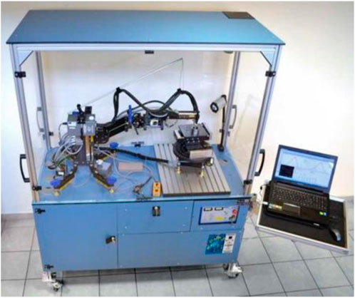
FIGURE 1. Proto iXRD diffractometer.
Due to the properties of the measured material, a Cr Kα lamp was used. The bearings were thoroughly cleaned and placed on an automated adjustable table under the measuring head, with the measured bearing surfaces parallel to the axis of the diffractometer arm. Prior to the actual measurement, the distance between the collimator and the measurement area was adjusted using the mounted Pointer on the collimator. Subsequently, the Auto Focus command was run, and the structure of the material to be measured was set to martensite in the Constants window of the measurement software.
The next step in the workflow was to place a titanium plate on the measurement surface to filter out interfering elements. After running the Gain command, an exposure displaying the profile began to form. After the profile was displayed, the plate was removed from the measurement surface and point (axial) and triaxial residual stress measurements followed.
A collimator with a diameter of 2 mm was used to focus the X-rays during the measurements, and the exposure time was set to 2 s to achieve the optimum intensity of the diffraction peak for tilting the measuring head. In the case of the triaxial residual stress measurements, the measurements were carried out while the sample was rotated on its axis, specifically by 60°, i.e., a total of 6 measurements were made in one rotation cycle. After the measurements, the Xrd Win measurement and evaluation software generated the measurement results and the corresponding result reports (Valíček et al., 2019; Šajgalík et al., 2018).
2.4 Method and measuring instrument used for measuring surface roughness
Surface roughness measurements were performed with the Alicona InfiniteFocus G5plus, which is a highly accurate, fast and flexible 3D optical device combining dimensional metrology and surface roughness measurement in one system. The measurement results are repeatable, with a possible vertical resolution of up to 10 nm. The reliable Focus Variation measurement combined with a high-quality anti-vibration system enables shape and roughness measurements also for large and heavy components directly in the production process. Infinite Focus is equipped with high-precision encoders, ensuring precise movement in all axes. With the automation interface, Infinite Focus can also be used for fully automatic measurements.
2.5 Technological operations carried out on bearing steels
2.5.1 Heat treatment
The heat treatment of bearing steels, i.e., quenching and tempering, was carried out externally at Koyo Bearings, Czech Republic.
Quenching took place in a quenching furnace divided into three sections, with all rings placed in a quenching basket (see diagram in the appendix). In Section 1, the temperature was 840°C for 20 min; in Section 2, the temperature was 850°C for 20 min; in Section 3, the temperature was 850°C for 20 min. After leaving the 3rd section of the quenching furnace, the rings were transferred to a salt bath at a temperature of about 200°C. The temperature of the salt bath was slightly variable as the salt bath increased slightly after the heated rings were inserted, so that it ranged from 200°C to 220°C.
The determined cooling rate was 100°C ± 10°C at a temperature of 781°C. IVF Smart Quench mobile measuring device was used to verify the cooling rate in the quenching bath. Cooling curves confirmed the correct rate of cooling. As shown in the figure, the upper critical cooling rate represents the lowest rate at which martensitic structures begin to form. In contrast, the lower critical speed defines the limit beyond which martensitic structures cease to form. A verification of the ARA diagram, i.e., the anisothermic breakdown of austenite, has been performed (Figure 2).
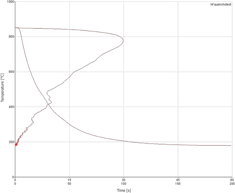
FIGURE 2. Time development of cooling of the quenching salt bath (from 850°C to 180°C) during heat treatment of bearing rings by quenching.
2.5.2 Turning
All turning operations were carried out in the company 3 T, Ltd. in Žilina. Turning was carried out on multiple spindle machines with single-purpose tools. The spindle was rotating at a speed of 500 rpm⋅ min−1, and the cycle time of production of 1 piece lasted for 10 s.
Cutting conditions, especially cutting speed and feed rate, have a significant influence on the generation of residual stresses in engineering practice.
The applied cutting speed vc of the lathe was determined according to the relation (1), in which D is the diameter of the workpiece of 43 mm; n is the number of revolutions of 500 rpm⋅ min-1.
When specific values are substituted into relation (1), the result is vc = 67.5 m⋅ min−1.
The feed rate used in vf of the lathe was determined according to the relation (2) in which f is feed per revolution with a value of 0.1 mm⋅ tooth−1; n number of spindle revolutions, rpm⋅ min−1.
When specific values are substituted into relation (2), the result is vf = 50 m⋅ min−1.
The heat-treated bearings were turned only at the specified cutting and feed rates, with a constant machined layer depth of 0.3 mm. Residual stresses were measured in the turning direction at six angles.
3 Measurement and evaluation of residual stress measurement results
After positioning and surface alignment, the diffractometer measurement was adjusted by tilting the head with the collimator in the β-axis to the shortest set position (35° in the presented case). There are an odd number of positions so that the angle β = 0° is always included in the middle (this is when the collimator irradiates perpendicularly over the surface). This is mainly due to the fact that laboratory instruments allow the sample (or collimator) to be rotated from 0° to 180°, i.e., all phases with all reflections are captured. In the presented case, the distance of the detectors (expected diffraction angle) is set according to the type of material (for steels, it is perlite, martensite, and austenite). In order to capture as many reflections as possible, an additional oscillation at each angular position (in the direction of the β axis) can be selected, in the presented case 3°. Next, at each position, the angle ψ, which determines the orientation of the sample relative to the collimator (or vice versa) in the direction of the β-axis, is included, and the current diffraction angle, FWHM and Breadth parameters (characteristics of the Gaussian distribution of reflections at the current angular position) are evaluated. From all distance changes, the partial relative elongations are evaluated and then the total residual stress is evaluated. Due to the complexity of the measurements, this result is reported only as a mean value.
3.1 Residual stress measurement procedure
All measurements of the residual stresses of bearing steels after technological treatments were performed with the Proto iXRD diffractometer in the laboratory of the Department of Machining and Manufacturing Technologies at the Faculty of Mechanical Engineering, University of Žilina (Figure 3).

FIGURE 3. Residual stress measurements of bearings at angular positions ψ.
Figure 3 shows the measurement of the residual stress σnap of turned-bearing steel L5tur in the centre of its cylindrical surface at the angular position ψ = 0° by a Proto iXRD diffractometer. An analogous procedure was followed to measure the residual stresses in the other five angular positions (60°, 120°, 180°, 240°, 300°). Also, the measurement of the residual stresses σrez of the bearing steel Lxque after quenching was carried out using the same workflow.
The measurement results presented in the form of regression relationships are, therefore, based on the setting of specific technological parameters, specific parameters and measurement conditions and the specific material used. For different settings, the regression relationships will only have a similar predictive value. It can be concluded that residual stresses of significantly loaded materials significantly affect the functionality of bearings. Therefore, their identification must not be neglected in engineering practice.
3.2 Comparison of measurement results depending on technological processing
A total of 8 different bearings were measured, 4 of which were in the quenched and tempered condition, and 4 were turned after heat treatment. All bearings were measured at the centre of their cylindrical surface, at six angular positions ψ (Figure 3). The results of the measurements were continuously recorded in tables and graphs, and the corresponding relationships predicting the residual stresses were assigned to them using an approximation method. The values of the residual stress measurements at the corresponding angular position ψ were interleaved with polynomial curves of degree 3 described by the corresponding regression equation with total accuracy of measurement (R2 = 1 in all cases investigated).
The selected angular positions corresponding to the presented tables, figures and equations: ψ = 0°, Table 2 and Figure 4, (Eqs 3, 4); ψ = 60°, Table 3 and Figure 5, (Eqs 5, 6); ψ = 120°, Table. 4 and Figure 6, (Eqs 7, 8); ψ = 180° and Table 5, Figure 7, (Eqs 9, 10); ψ = 240°, Table 6 and Figure 8, (Eqs 11, 12); ψ = 300°, Table 7 and Figure 9, (Eqs 13, 14).

TABLE 2. Residual stress of bearings Lx in angular position ψ = 0°.
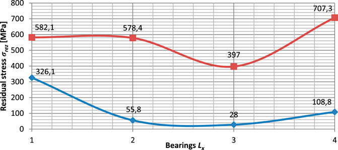
FIGURE 4. The waveform of residual stresses of Lx bearings at angular position ψ = 0° (blue curve—after quenching; red curve—after quenching and turning).

TABLE 3. Residual stress of bearings Lx in angular position ψ = 60°.
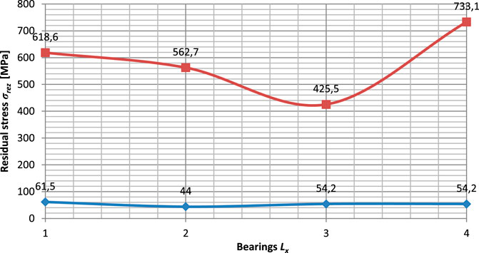
FIGURE 5. The waveform of residual stresses of Lx bearings in angular position ψ = 60° (blue curve—after quenching; red curve—after quenching and turning).
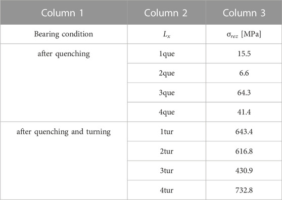
TABLE 4. Residual stress of bearings Lx in angular position ψ = 120°.
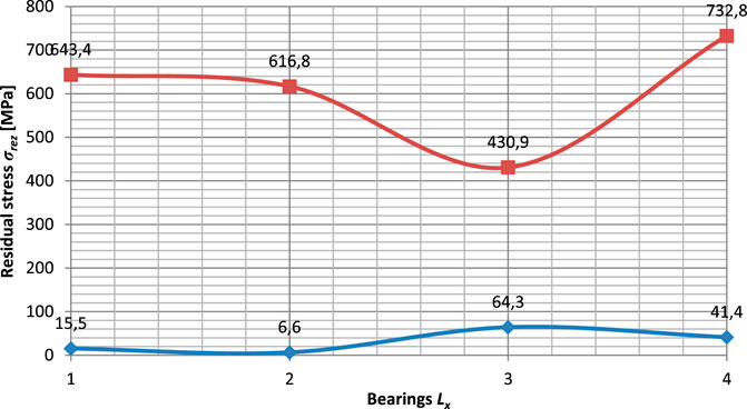
FIGURE 6. The waveform of residual stresses of Lx bearings in angular position ψ = 120° (blue curve—after quenching; red curve—after quenching and turning).
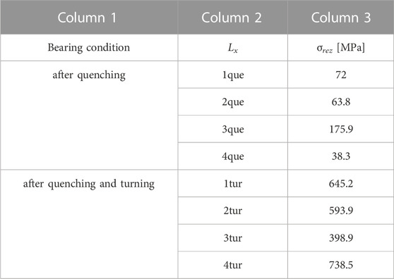
TABLE 5. Residual stress of bearings Lx in angular position ψ = 180°.
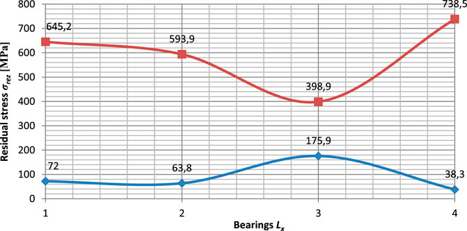
FIGURE 7. The waveform of residual stresses of Lx bearings in angular position ψ = 180° (blue curve—after quenching; red curve—after quenching and turning).

TABLE 6. Residual stress of bearings Lx in angular position ψ = 240°.
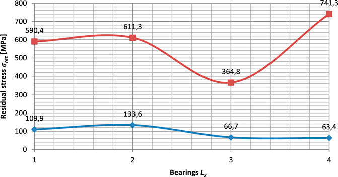
FIGURE 8. The waveform of residual stresses of Lx bearings in angular position ψ = 240° (blue curve—after quenching; red curve—after quenching and turning).
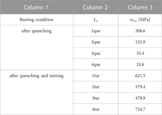
TABLE 7. Residual stress of bearings Lx in angular position ψ = 300°.
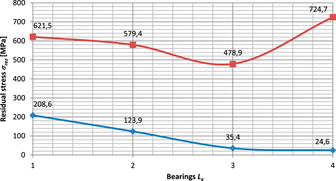
FIGURE 9. The waveform of residual stresses of Lx bearings in angular position ψ = 300° (blue curve—after quenching; red curve—after quenching and turning).
Tables 2–7 contain 5 columns, with columns 1 and 2 presenting the Lx deposits according to their state of processing. Column 3 contains the values of the measured residual stresses σrez at the angular positions ψ.
From Figure 4, we got Eqs 3, 4
From Figure 5, we got Eqs 5, 6
From Figure 6, we got Eqs 7, 8
From Figure 7, we got Eqs 9, 10
From Figure 8, we got Eqs 11, 12
From Figure 9, we got Eqs 13, 14
3.3 Comparison of measurement results depending on technological processing
The results of the measurements recorded in the tables (Tables 2–7) were the basis for the construction of the graph (Figure 10) expressing the comparative waveforms of the residual stresses σrez for Lxque bearings after heat treatment, depending on the selected angular positions ψ. The waveforms were assigned the corresponding relations predicting the residual stresses using an approximation method. The values of the residual stress measurements at the corresponding angular position ψ were interleaved with the polynomial curves of degree 5 described by the corresponding regression equation with total accuracy of measurement (R2 = 1 in all investigated cases) (Eqs 15–18).

FIGURE 10. Comparison waveforms of residually stressed σrez of Lxque bearings after heat treatment in angular positions ψ.
3.4 Comparison of measurement results depending on selected angular positions after heat treatment and subsequent turning
The results of the measurements recorded in the tables (Tables 2–7) were the basis for the construction of the graph (Figure 11) expressing the comparative waveforms of the residual stresses σrez of the Lxtur bearings after quenching and subsequent turning, depending on the selected angular positions ψ. The waveforms were assigned the corresponding relations predicting the residual stresses using an approximation method. The values of the residual stress measurement results at the respective angular position ψ were interleaved with the polynomial curves of degree 5 described by the respective regression equation with total accuracy of measurement (R2 = 1 in all investigated cases) (Eqs 19–22).
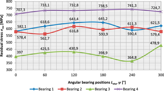
FIGURE 11. Comparison plot of residual stresses σrez of Lxtur bearings after heat treatment and turning in angular positions ψ.
3.5 Evaluation of residual stress distribution on bearing steel
The mean values of the residual stresses of Lx bearings at the angular positions ψ were evaluated as arithmetic averages, namely, as the mean values of a for Lxque bearings after heat treatment (Eq. 23) and as the mean value of b for the Lxtur bearings after heat treatment and subsequent turning (Eq. 24).
The course of these mean values in angular positions is shown in the graph in Figure 12.
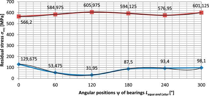
FIGURE 12. Comparison plot of mean values of residual stresses σrez of Lxque and Lxtur bearings after heat treatment and after heat treatment and turning in angular positions ψ blue curve—after quenching; red curve—after quenching and turning.
The values of the residual stress results measured on Lxque and Lxtur bearings at the respective angular positions were interleaved with the polynomial curves of degree 5 (Figure 12) described by the respective regression equations with total accuracy of measurement (in all investigated cases R2 = 1) (Eqs 25, 26).
Figures 13, 14 show how uniformly the residual stresses of the bearing steel are distributed after the technological treatments, i.e., how the measured values trend or oscillate around the mean value and what the interval of dispersion is.
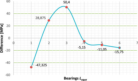
FIGURE 13. The waveform of the differences of all residual stresses measured on heat-treated bearing steels, relative to their mean value.
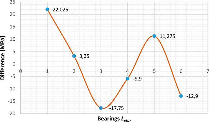
FIGURE 14. The waveform of the differences measured on heat treated and subsequently turned bearing steel, relative to their mean value.
The mean value of the residual stress on the thermally treated bearings measured at all angular positions is 82.35 MPa. The variance of the residual stresses measured at the selected angular positions increases and then decreases (Figure 13). Considering that the variance of the investigated deviations is measurable in the total interval of 97.73 MPa, it can be concluded that it is relatively significant with respect to the overall mean value of the residual stresses.
The mean value of the residual stress on the heat treated and subsequently turned bearings measured at all selected angular positions is 588.23 MPa. The variance of the residual stresses measured at the selected angular positions is alternately decreasing, increasing and decreasing (Figure 14). Considering the fact that the variance of the investigated variance is measurable over the total interval of 1,151.12 MPa, it can be concluded that it is relatively significant with respect to the determined mean value of the residual stresses and higher than the residual stress distribution on the heat-treated bearing steel only.
3.6 Results of surface roughness measurements
In the case of surface roughness measurements, the surfaces of quenched and turned bearings were measured, with the measurements repeated ten times. The roughness parameters Ra, Rq, Rz were measured comparatively, with Ra chosen as the most relevant parameter for the comparison of values. Measurements were again taken at each of the bearing positions. It can be pointed out that when comparing the measured roughness values (Tables 8, 9; Figure 15), the values of quenched bearings are much higher than those of turned bearings. However, no relatively significant deviation from the standard is evident for either group of measurements.
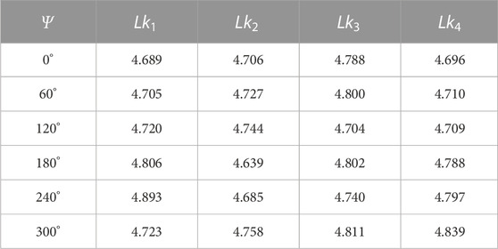
TABLE 8. Roughness values Ra (μ m) of the surface of quenched Lk1 to Lk4 bearings in positionsΨ.
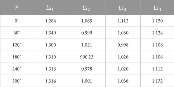
TABLE 9. Roughness values Ra (μ m) of the surface of turned Ls1 to Ls4 bearings in positionsΨ.
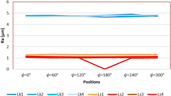
FIGURE 15. Comparison of the roughness of quenched (Lk1 to Lk4) and turned (Ls1 to Ls4) bearings.
3.7 Analytical description of residual stresses for surface roughness after turning and quenching
The initial basis for deriving further analytical relations in this application case is also the copyrighted patent, from which relations (Eqs 27–29) were taken for further analytical description.
or
After adjustment, relationships involving the independent variable Ra (Eqs 30–32) can be obtained,
from which we can obtain the relation (Eq. 31) for the roughness Ra, where Ra0 roughness on the neutral plane h0 is equal to 3.7 µm = const.
It can be assumed that the source of residual stress generation is the mechanical condition of the surface layer, which is reflected in the surface roughness Ra, especially in the cutting tool marks. The authors’ new ambition was to analytically capture the influence of the subsurface layers down to the core of the material (Harničárová et al., 2013; Valíček et al., 2020). In this respect, the structural grain size Dgr and its alteration due to stresses of different nature also gained importance. On this basis, relationships (Eqs 32–39) can be derived. In these new relations, the broader dependence σrez = f (Dgr, Ra) is already respected. Theoretically, other related dependent variables resulting from, e.g., the graph in Figure 16 can be added to this implicit equation. We know that capturing a larger number of dependent variables analytically makes the calculations more accurate and increases their predictive and application capabilities.
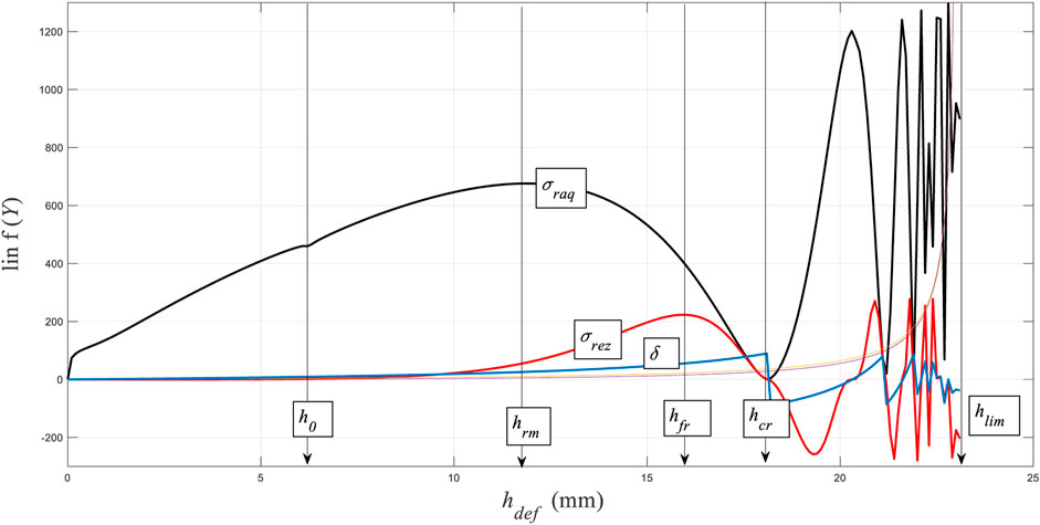
FIGURE 16. Dependence of residual stress on deformation level.
After adjustment, we obtain relationships involving both independent variables, i.e., both surface roughness and structural grain size, according to relations (Eqs 32–39).
The following relations (Eqs 36–39) apply analogously for the structural grain size.
respectively
Dgr0 - grain size on the neutral plane h0 (µm)
hdef - deformation level (mm)
Emat - Young’s modulus (MPa)
RarezS - grain size after turning (µm)
RarezK - grain size after quenching (µm)
σrezS - residual stress after turning (µm), σrezK - residual stress after quenching (µm).
4 Discussion of measurement results
In the first processing of the set of measurement results, the dependence of residual stresses on technological operations, i.e., after quenching and tempering and after quenching, tempering, and subsequent turning, was identified and compared. Based on the declared waveforms of these results (Figures 3–8) measured at the angular positions after heat treatment, it appears that quenched and tempered bearing steels show significantly lower residual stress values at the material surface than bearing steels quenched, tempered, and subsequently turned. The clear quantitative differences in all measured results are fully consistent with the qualitative theoretical assumptions since the increase in residual stress values is mainly due to re-machining, i.e., re-loading of the material.
In the second processing of the set of measurement results (Figures 9, 10), the dependence of residual stresses on angular positions was identified and compared. While in Figure 8, considerable oscillations of locally overlapping residual stress waveforms measured after heat treatment can be observed, in Figure 10, only relatively slight oscillations of widely separated residual stress waveforms measured after heat treatment and subsequent turning can be observed. The presented results of the residual stress distributions can again be interpreted qualitatively as showing that the residual stress distributions measured on bearing steels quenched and tempered only show significantly better values than the residual stress distributions measured on bearing steels quenched, tempered, and subsequently turned. The clear differences in all measured results are entirely consistent with the theoretical assumptions since the significant increase in residual stress values is mainly due to re-machining, i.e., re-loading of the material.
Different results of the measurement sets are caused by different distributions of residual stresses due to anisotropy of thermal stresses of the material under given technological conditions and are also increased by different shape inaccuracies of production. These effects combine to give locally different residual stress concentrations.
The magnitude and shape of the residual stresses depend on a number of transformation effects, and the relationships between the transformation parameters are always interactive. The characteristics of the residual stresses of selected bearing steels were measured and predicted approximately, both after heat treatment and after heat treatment, followed by turning. The presented results of the bearing steel residual stress measurements will be subsequently used for the analytical prediction of residual stresses as a function of surface roughness, grain size, and Young’s modulus.
It will be challenging but interesting and beneficial to investigate the characteristics of residual stresses in relation to the state of the subsurface layers of the material because residual stresses exist not only on the surface with a thickness of the order of micrometres but depending on the intensity of heat treatment and machining, they are inevitably projected to the core of the material.
The residual stresses were measured on the turned rings and then on the heat-treated rings, i.e., hardened and tempered. In this case, the heat treatment is not carried out primarily to remove residual stresses, but to increase the hardness of the material, which reached a value of 60–64 HR after hardening. The aim of the paper was to propose a method for the identification of residual stresses during turning and hardening in order to formulate new analytical relations with a mathematical description of the relationships to surface roughness Ra and structural grain size Dgr. The contribution lies in a deeper elucidation of the origin and existence of residual stresses in the material. The results of residual stress measurements in bearing steel presented here are subsequently used for the analytical prediction of residual stresses as a function of surface roughness, grain size and Young’s modulus.
Therefore, the novelty and contribution of the presented work lies mainly in the establishment of new analytical relations (Eqs 32–39) for the prediction of the resulting surface roughness after turning and hardening in relation to residual stresses. In solving the subject problem, we have used the experience from the patent (Institute of Geonics AS CR, 2015). Although the subject patented solution is primarily based on cutting with a flexible AWJ beam, where the cut and chip formation can be best studied, this does not mean that the results of the study do not apply more universally to cutting with a fixed turning knife. The only difference in principle is that for the fixed knife, we do not consider the curvature of the cut trace and, therefore, the angle δ = 0° and in the calculation Eqs 27–31 cos δ = 1. Thus, we easily obtain the graph in Figure 16 after substituting it into the declared calculation equations. Dependence of residual stress on deformation level hdef. Thus, constructed waveforms of the subject technological variables σrez, Ra, and Dgr give a simple and analytically based picture of the mechanism of residual stress formation. From the graph in Figure 16 alone, an analytical idea of the close connection between the stresses σraq (the main envelope of the engineering stress in the chip) and the residual stress σrez) is already apparent. The maximum σrez is reached at the level of hfr, where the material structure of the chip is disrupted and the mechanical stress potential is transferred to the contact material in its vicinity up to the limiting depth of influence hlim, in successive frequency cycles of alternating compressive and tensile stresses. The frequency of the oscillations is determined by the technological stresses and the type of chip material. All these aspects are analogously, in detail and analytically developed in the patent in question.
The advantage of the proposed method is the measurement of residual stresses in the material by means of non-destructive tests, thus it is a non-destructive quantification of residual stresses. In destructive tests (metallographic sections and cut-outs), we only observe the ring opening (due to residual stresses) and compare this opening with a specific reference value. For each type of bearing ring, of which there are thousands (for different ring sizes, different wall thicknesses, etc.), this reference is different, and the interpretation is quite challenging and ambiguous. It can be assumed that the determination of residual stresses by non-destructive methods on selected sample types of bearing rings and subsequent comparison with the results from metallographic sections can simplify and to some extent predict the residual stresses after hardening and the subsequent behaviour of the material during further machining operations (especially grinding and superfinishing of the bearing ring surface).
The limitation of the proposed method lies in the requirement to use measuring equipment such as X-ray, ultrasonic and roughness meters, either in stationary or mobile versions. The limiting factor is their relatively high purchase price and the associated reluctance to apply the proposed method, especially in smaller private enterprises.
Future work to follow will be of two types. In the future, we plan to present a publication providing the results of the comparison of destructive and non-destructive methods as well as the algorithmization of residual stresses in the material. Furthermore, we expect that the proposed non-destructive measurements of residual stresses will also be used on raw material intended for turning bearing rings, i.e., on semi-finished tubes, bars or forgings, as they will provide a good means of argumentation (especially in terms of quality) when negotiating with suppliers of these semi-finished products.
5 Conclusion
On the basis of the measurements, residual stresses after turning and quenching of the bearing steel were identified. Residual stress measurements were performed on all bearing rings at six selected angular positions (0°, 60°, 120°, 180°, 240°, 300°) in the centre of their cylindrical surfaces. The results of the measurements were compared depending on the technological treatment and depending on the selected angular positions, both after heat treatment and after turning followed by heat treatment.
In order to quantify the rate of change of surface tension, the average values of residual stresses of the two groups of bearings and the trends of deviations from these average values were determined. The average value of residual stress on the turned bearing rings measured at all selected angular positions was 588.23 MPa, with a trend of gradually decreasing, increasing and decreasing values, and the variance of the investigated deviations was in the total interval of 1,151.12 MPa. The average value of the residual stress on the hardened bearing rings measured at all angular positions was 82.35 MPa, with an increasing and decreasing trend of the measured values, and the variance of the investigated deviations was in the total interval of 97.73 MPa.
The aim of this paper was to propose and apply a non-destructive method for the identification of residual stresses during chip machining and subsequent hardening in order to formulate new analytical relationships with a mathematical description of the relationships to surface roughness Ra and structural grain size Dgr.
The contribution lies in the quantification of the residual stresses of the material after chip machining and after hardening. The novelty and contribution of the present work lies in the establishment of new analytical relations (Eqs 32–39) for the prediction of the resulting surface roughness after turning and hardening in relation to the residual stresses.
There is scope for more comprehensive studies in the future with measurements of residual stresses after all technological operations, i.e., turning, heat treatment and finishing after heat treatment (grinding, honing, superfinishing). These data can be used independently, for example, in negotiations with raw or semi-finished material suppliers, and can be compared with surface roughness.
Data availability statement
The raw data supporting the conclusion of this article will be made available by the authors, without undue reservation.
Author contributions
MaŠ, JV, and MH contributed to conception and design of the study. MiŠ, AC, and MD organized the experiment. HT performed the statistical analysis. JV wrote the first draft of the manuscript. MKu and MKa wrote sections of the manuscript and verified the experimental data. All authors contributed to the article and approved the submitted version.
Funding
This research work has been supported by the Scientific Grant Agency of the Ministry of Education, Science, Research and Sport of the Slovak Republic under grant number VEGA 1/0236/21, the Slovak Research and Development Agency under grant number APVV-19-0526 and by the University of Žilina project 313011ASY4 funded by the Ministry of Education, Science, Research and Sport of the Slovak Republic.
Conflict of interest
The authors declare that the research was conducted in the absence of any commercial or financial relationships that could be construed as a potential conflict of interest.
Publisher’s note
All claims expressed in this article are solely those of the authors and do not necessarily represent those of their affiliated organizations, or those of the publisher, the editors and the reviewers. Any product that may be evaluated in this article, or claim that may be made by its manufacturer, is not guaranteed or endorsed by the publisher.
References
Ahmadpoor, S. S., Khajehzadeh, M., and Razfar, M. R. (2022). Finite element simulation and experimental investigation of machining induced residual stresses in ultrasonic elliptical vibration-assisted turning. Mach. Sci. Technol. 26, 377–395. doi:10.1080/10910344.2022.2129980
Bedekar, V., Voothaluru, R., Bunn, J., and Hyde, R. S. (2019). Measurement and prediction of through-section residual stresses in the manufacturing sequence of bearing components. CIRP Ann. 68, 57–60. doi:10.1016/j.cirp.2019.03.004
Biasibetti, G. R. D. S., Nunes, R. M., De Cesaro Cavaler, L. C., Vieira Braga Lemos, G., and Rocha, A. D. S. (2021). Turning parameters effects in residual stresses of AISI 1045 steel. Proc. Inst. Mech. Eng. Part B J. Eng. Manuf. 235, 1498–1506. doi:10.1177/0954405421990118
Butola, R., Singh, R. P., Choudhary, N., Mer, K. K. S., Bhaskar, J., and Singari, R. M. (2021). Fabrication of FSW tool pins through turning of H13 tool steel: a comparative analysis for residual stresses. J. Adv. Manuf. Syst. 21, 351–366. doi:10.1142/s0219686722500135
Elsheikh, A. H., Shanmugan, S., Muthuramalingam, T., Thakur, A. K., Essa, F. A., Ibrahim, A. M. M., et al. (2021). A comprehensive review on residual stresses in turning. Adv. Manuf. 10, 287–312. doi:10.1007/s40436-021-00371-0
Harničárová, M., Valíček, J., Öchsner, A., Grznárik, R., Kušnerová, M., Neugebauer, J., et al. (2013). Predicting residual and flow stresses from surface topography created by laser cutting technology. Opt. Laser Technol. 52, 21–29. doi:10.1016/j.optlastec.2013.03.024
Hua, Y., Liu, Z., Wang, B., and Jiang, J. (2019). Residual stress regenerated on low plasticity burnished inconel 718 surface after initial turning process. J. Manuf. Sci. Eng. 141. doi:10.1115/1.4045060
Huang, K., Yang, W., and Ye, X. (2018). Adjustment of machining-induced residual stress based on parameter inversion. Int. J. Mech. Sci. 135, 43–52. doi:10.1016/j.ijmecsci.2017.11.014
Institute of Geonics AS CR, , Valíček, J., Borovička, A., Hloch, S., and Hlaváček, P. (2015). Method for the design of a technology for the abrasive waterjet cutting of materials. U.S. Patent.9073175.
Javadi, H., Jomaa, W., Songmene, V., Brochu, M., and Bocher, P. (2019). Inconel 718 superalloy controlled surface integrity for fatigue applications produced by precision turning. Int. J. Precis. Eng. Manuf. 20, 1297–1310. doi:10.1007/s12541-019-00145-6
Jouini, N., Revel, P., and Thoquenne, G. (2020). Influence of surface integrity on fatigue life of bearing rings finished by precision hard turning and grinding. J. Manuf. Process. 57, 444–451. doi:10.1016/j.jmapro.2020.07.006
Li, Y., Zhang, D., Wang, H., Ye, G., He, R., and Cong, W. (2022). Theoretical and experimental investigations on rotary ultrasonic surface micro-machining of brittle materials. Ultrason. Sonochem 89, 106162. doi:10.1016/j.ultsonch.2022.106162
Liu, M., Takagi, J. I., and Tsukuda, A. (2004). Effect of tool nose radius and tool wear on residual stress distribution in hard turning of bearing steel. J. Mat. Process. Technol. 150, 234–241. doi:10.1016/j.jmatprotec.2004.02.038
Ma, Y., Zhang, J., Feng, P., Yu, D., and Xu, C. (2018). Study on the evolution of residual stress in successive machining process. Int. J. Adv. Manuf. Technol. 96, 1025–1034. doi:10.1007/s00170-017-1542-0
Maroju, N. K., and Pasam, V. K. (2019). FE modeling and experimental analysis of residual stresses in vibration assisted turning of Ti6Al4V. Int. J. Precis. Eng. Manuf. 20, 417–425. doi:10.1007/s12541-019-00021-3
Outeiro, J. C., Pina, J. C., M'saoubi, R., Pusavec, F., and Jawahir, I. S. (2008). Analysis of residual stresses induced by dry turning of difficult-to-machine materials. CIRP Ann. 57, 77–80. doi:10.1016/j.cirp.2008.03.076
Pape, F., Coors, T., and Poll, G. (2020). Studies on the influence of residual stresses on the fatigue life of rolling bearings in dependence on the production processes. Front. Mech. Eng. 6. doi:10.3389/fmech.2020.00056
Pape, F., Maiss, O., Denkena, B., and Poll, G. (2019). Enhancement of roller bearing fatigue life by innovative production processes. Ind. Lubr. Tribol. 71, 1003–1006. doi:10.1108/ilt-07-2018-0254
Pape, F., Neubauer, T., Maiß, O., Denkena, B., and Poll, G. (2017). Influence of residual stresses introduced by manufacturing processes on bearing endurance time. Tribol. Lett. 65, 1–8.
Peng, H., Dong, P., Cheng, X., Zhang, C., Tang, W., Xing, Y., et al. (2020). Semi-empirical prediction of residual stress distributions introduced by turning inconel 718 alloy based on lorentz function. Materials 13, 4341. doi:10.3390/ma13194341
Peng, H., Tang, W., Xing, Y., and Zhou, X. (2021). Semi-empirical prediction of turned surface residual stress for inconel 718 grounded in experiments and finite element simulations. Materials 14, 3937. doi:10.3390/ma14143937
Šajgalík, M., Czanova, T., Zauskova, L., Drbul, M., Sadilek, M., and Valicek, J. (2018). Triaxial analysis of residual stress in surface layers after high feed machining using X-ray diffractometer. MATEC Web Conf. 157, 07012. doi:10.1051/matecconf/201815707012
Sjöström, J., Durga, A., and Lindwall, G. (2022). Linkage of macro- and microscale modeling tools for additive manufacturing of steels. Front. Mat. 9. doi:10.3389/fmats.2022.797226
Soori, M., and Arezoo, B. (2022). A review in machining-induced residual stress. A Review in Machining-Induced Residual Stress. J. New Technol. Mat. 12, 64–83.
Tong, J. L., Zhao, B., and Jiao, F. (2012). Study on residual stress of GCr15 bearing steel under ultrasonic vibration turning. Key Eng. Mat. 522, 173–177. doi:10.4028/www.scientific.net/kem.522.173
Valíček, J., Czán, A., Harničárová, M., Šajgalík, M., Kušnerová, M., Czánová, T., et al. (2019). A new way of identifying, predicting and regulating residual stress after chip-forming machining. Int. J. Mech. Sci. 155, 343–359. doi:10.1016/j.ijmecsci.2019.03.007
Valíček, J., Harničárová, M., Kušnerová, M., Šajgalík, M., Kmec, J., Kopal, I., et al. (2020). Reverse reconstruction of surface topography from residual stress after chip-forming machining of the material. Mater. Werkst. 51, 579–585. doi:10.1002/mawe.202000017
Wang, W., Salvatore, F., and Rech, J. (2020). Characteristic assessment and analysis of residual stresses generated by dry belt finishing on hard turned AISI52100. J. Manuf. Process. 59, 11–18. doi:10.1016/j.jmapro.2020.09.039
Xueping, Z., Erwei, G., and Richard Liu, C. (2009). Optimization of process parameter of residual stresses for hard turned surfaces. J. Mat. Process. Technol. 209, 4286–4291. doi:10.1016/j.jmatprotec.2008.10.011
Zheng, M., Guo, Q., Kong, J., and Sun, Y. (2022). Surface stress distribution of thin-walled spherical pure iron component after turning process. Proc. Inst. Mech. Eng. Part C. J. Mech. Eng. Sci. 237, 103–119. doi:10.1177/09544062221118810
Keywords: residual stress, bearing steel, measurement, evaluation of measurement results, modelling
Citation: Šafář M, Valíček J, Harničárová M, Šajgalík M, Tozan H, Kušnerová M, Drbúl M, Kadnár M and Czán A (2023) Proposal for the identification of residual stresses after turning and hardening of bearing steel. Front. Mater. 10:1238816. doi: 10.3389/fmats.2023.1238816
Received: 12 June 2023; Accepted: 31 July 2023;
Published: 24 August 2023.
Edited by:
Frédéric Charles Lebon, Aix-Marseille Université, FranceReviewed by:
Pavlo Maruschak, Ternopil Ivan Pului National Technical University, UkraineWenbin Zhou, University of Dundee, United Kingdom
Copyright © 2023 Šafář, Valíček, Harničárová, Šajgalík, Tozan, Kušnerová, Drbúl, Kadnár and Czán. This is an open-access article distributed under the terms of the Creative Commons Attribution License (CC BY). The use, distribution or reproduction in other forums is permitted, provided the original author(s) and the copyright owner(s) are credited and that the original publication in this journal is cited, in accordance with accepted academic practice. No use, distribution or reproduction is permitted which does not comply with these terms.
*Correspondence: Marta Harničárová, bWFydGEuaGFybmljYXJvdmFAdW5pYWcuc2s=