 Xuewei Huang1
 Li Li
Li Li Xiaohui Ruan
- 1School of Mechanics and Safety Engineering, ZhengZhou University, ZhengZhou, China
- 2CAS Key Laboratory of Mechanical Behavior and Design of Materials, University of Science and Technology of China, Hefei, China
- 3Institute of Advanced Technology, University of Science and Technology of China, Hefei, China
Magnetorheological Elastomers (MREs) are smart materials with the ability to modulate their mechanical properties by changing the external magnetic fields, offering extensive potential for applications requiring variable stiffness and damping devices. A comprehensive mechanical model that explains the influence of loading conditions on the performance of MRE is crucial for understanding their intrinsic mechanisms during operation, and for the design, analysis, and improvement of intelligent energy dissipation and vibration control devices based on MRE. In this study, a four-parameter mechanical model was established to reveal the intrinsic mechanisms about the effects of external magnetic fields, loading frequency, and strain amplitude on the storage modulus, loss modulus, equivalent stiffness, and equivalent damping of MRE materials. The dynamic mechanical properties of the MRE materials prepared from carbonyl iron powder and PDMS were tested, and parameter identification of the established model was performed. The comparison results between the theoretical model analysis and the testing results demonstrated that the proposed mechanical model effectively characterizes and predicts the mechanical behavior of MRE materials. Furthermore, based on the prepared MRE materials, a stiffness-controllable energy dissipator operating in shear mode was designed and fabricated, and the mechanical performance of the shear energy dissipator was experimentally evaluated. This research provides a basis and guidance for the design and mechanical performance analysis of devices based on MRE, confirming the feasibility of MRE materials as core components in intelligent energy dissipation devices.
1 Introduction
Magnetorheological materials (MREs) are a type of smart material that can respond to magnetic fields. When the external magnetic fields are applied on the MRE, the storage modulus of the MRE can multiply. When the external fileds are removed, the storage modulus of the MRE can return to the original state. The transformation process described above can be done whithin milliseconds (Biswal and Rao, 2016; Yang et al., 2019; Morillas and de Vicente, 2020). Due to their ability of continuously, rapidly, and reversible changeing in their mechanical properties under the control of an external magnetic field, MRE have wide-ranging applications in many areas such as seismic resistance in buildings (Selvaraj and Ramamoorthy, 2020; Yang et al., 2020; Zhao et al., 2021), vibration damping in vehicles (Sun et al., 2017; Du et al., 2020; Jin et al., 2020; Rocca and Russo, 2021), and precision instruments (Golini et al., 1999; Xing et al., 2015; Choopani et al., 2022). Furthermore, MRE materials possess the advantages of both magnetorheological materials and elastomers, overcoming drawbacks such as settling of magnetorheological fluids, poor stability, and the need for sealing. As a result, they have become a hot topic in the field of magnetorheological material applications in recent years (Xing et al., 2015; Yang et al., 2019; Nam et al., 2020; Selvaraj and Ramamoorthy, 2020; Yang et al., 2020).
Pre-structured anisotropic MRE exhibit significantly better mechanical properties compared to isotropic MRE, with higher magneto-induced modulus and higher magnetorheological effects (MR effect) (Ginder et al., 2000; Chen et al., 2007; Sun et al., 2008; Nam et al., 2020). Currently, extensive research has been conducted by researchers through experimental and theoretical analysis to study the performance and applications of MRE materials. These studies can be divided into two groups based on the material working mode: tension-compression mode and shear mode. In the shear mode, the research on the mechanical properties of MRE can be further divided into two parts. One part focuses on characterizing the mechanical properties of MRE materials, such as magnetorheological effect, storage modulus, and loss factor (Agirre-Olabide and Elejabarrieta, 2016; Ju et al., 2016; Dargahi et al., 2019; Nam et al., 2020). The other part involves characterizing the performance of devices based on MRE materials, such as tunable isolators, dampers, and vibration isolators (Ginder et al., 2001; Ni et al., 2009; Yang et al., 2016; Kavlicoglu et al., 2020).
Current research mainly focuses on the mechanical properties of MRE materials under dynamic loading conditions, including storage modulus, loss modulus, loss factor, as well as the equivalent stiffness and damping of devices based on MRE materials. However, there has been relatively limited research on the intrinsic mechanisms of MRE materials in the shear working mode. Existing theoretical models for studying the performance of MRE materials are either based on viscoelastic models, which can explain the viscoelastic mechanical properties but fail to explain the magneto-induced mechanical behavior of MRE, or based on magnetic dipole models, which can explain the magneto-induced mechanical behavior but cannot account for the frequency- and time-dependent viscoelastic characteristics of the materials. Both models have their limitations. Therefore, a comprehensive mechanical model that can explain the influence of loading conditions on the performance of MRE materials is crucial for understanding the intrinsic mechanisms of MRE materials during operation and for the design, analysis, and improvement of smart energy dissipation and vibration reduction devices based on MRE materials.
In this study, a four-parameter magnetic dipole-viscoelastic comprehensive mechanical model was established to elucidate the inherent mechanisms of MRE material performance under loading conditions. Shear mechanical tests were performed on the prepared MRE samples using a sinusoidal loading method. The stress-strain relationships of the MRE samples under different cyclic loading conditions were obtained, and the effects of external magnetic field, loading frequency, and strain amplitude on the storage modulus, loss modulus, equivalent stiffness, and equivalent damping of MRE materials were analyzed. The mechanical model was parameterized through dynamic mechanical testing of the prepared MRE materials. Finally, a shear-mode energy dissipator was designed and fabricated, and the mechanical performance of the shear energy dissipator was experimentally tested. A comparison between the theoretical model and experimental results demonstrated that the comprehensive mechanical model established in this study can effectively characterize and predict the mechanical behavior of MRE materials.
2 Mechanical model
The mechanical properties of MRE can be precisely controlled by an applied magnetic field. These mechanical characteristics depend on the chain-like structure of magnetic particles within the MRE material. Therefore, current research mainly focuses on the magnetic dipole mechanical properties of MRE by considering the internal magnetic dipole model of MRE materials. However, if only the internal particle microstructure is considered, using the widely applied magnetic dipole model without considering the viscoelastic mechanical properties of the polymer matrix, although it can explain the variation of MRE’s mechanical properties with the magnetic field, it fails to explain the frequency dependence and time dependence, which are related to the viscoelastic properties of the material. Therefore, it is necessary to consider the influence of both the microstructural magnetic particle arrangement and the macroscopic viscoelastic properties of the polymer matrix.
Based on the above reasons, this study establishes a comprehensive magnetic dipole-viscoelastic mechanical model that takes into account both the microstructural magnetic particle arrangement and the macroscopic viscoelastic properties of the polymer matrix in MRE materials. By considering these two aspects, the model explains the inherent mechanisms behind the effects of applied magnetic field, loading frequency, and strain amplitude on the dynamic mechanical properties of MRE materials.
Previous research has shown that the magnetic particles inside anisotropic MRE materials do not align in an ideal linear chain structure along the direction of prestructuring but rather distribute in a wavy, non-linear chain structure within the matrix (Rudykh and Bertoldi, 2013; Wen et al., 2018), [see Supplementary Figure S1]. Therefore, when an external magnetic field is applied, the internal chain-like arrangement of magnetic particles undergoes structural changes under the influence of the magnetic field, resulting in alterations of the mechanical properties of MRE materials.
The magneto-mechanical properties of MRE originate from the magnetization and redistribution of magnetic particles within the material. An idealized two-dimensional microstructure is depicted in Figure 1, consisting of three adjacent magnetic particles. Taking the center of particle 1 as the origin, the Y-axis is established along the main chain direction of the particle chain, and the X-axis is perpendicular to the Y-axis. The dark positions represent the original positions of the magnetic particles within the MRE material, while the blue positions represent the locations to which the magnetic particles move under shear loading. Under the influence of an applied magnetic field, the changes in magnetic interaction force and magnetic chain-induced stiffness between adjacent particles can be derived as follows.
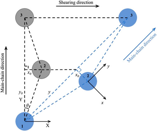
FIGURE 1. Magnetic dipole mechanics model.
For this structure, the magnetic force on particle 2 by particle 1 in the presence of an applied magnetic field is
Where
The magnetic force on particle 2 by particle 1 in the Y direction is
Then the increased magnetostriction in the y-axis direction due to the magnetic interaction of the particles is
Based on literature research, it is known that the s value of pre-structured MRE materials is less than 0.4 (Wen et al., 2018). Eq. 3 can be expressed as
Based on literature research, when the applied magnetic field remains constant and the shear strain of the MRE material increases, the influence of the material’s Poisson effect on its mechanical properties can be neglected (Wen et al., 2018), i.e., x is constant. Therefore, the magnetic force exerted by particle 1 on particle 2 in the Y-direction can be expressed as
Then the increased magnetostriction in the y-axis direction due to the magnetic interaction of the particles is
In this case, as the y-value increases and t increases, K (t) decreases [see Supplementary Figure S2B], while K (B) remains constant. Consequently, the magnetic stiffness Ky decreases. Therefore, the magnetic stiffness of the MRE material decreases with increasing shear strain amplitude.
The magnetorheological energy storage modulus of MRE is mainly determined by the magnetic stiffness Ky, which is represented by
The magnetorheological loss modulus
The magnetic force on particle 2 by particle 1 in the x-direction is
The equation can be expressed as
When the external magnetic field remains constant and the shear strain of the material increases, assuming the Poisson’s effect of the material is negligible (x remains constant), the magnetic force exerted on particle 2 by particle 1 in the Y direction can be expressed as
In this case, as the y-value increases and t increases, F (t) decreases while F (B) remains constant. The transverse magnetic force Fx decreases [see Supplementary Figure S3B]. Therefore, as the shear strain amplitude increases, the magnetic loss modulus of MRE materials decreases.
The above discussion focuses on the influence of the internal magnetic particle structure of MRE materials at the micro-level on their mechanical properties, providing an explanation for the mechanisms by which external magnetic fields and strain amplitudes affect the mechanical behavior of MRE materials. However, it is important to note that the loading frequency also has a significant impact on the mechanical properties of MRE materials. The effects of loading frequency on the mechanical behavior of MRE materials cannot be fully explained by the micro-level magnetic dipole model alone. Therefore, it is necessary to combine a macro-level viscoelastic mechanical model of the MRE material matrix to further elucidate the mechanical properties of MRE materials.
Based on the analysis of the non-linear magnetic dipole mechanical model and the viscoelastic mechanical model of the polymer matrix, this study proposes a comprehensive magnetic dipole-viscoelastic mechanical model for MRE materials, as shown in Figure 2, to describe the mechanical performance of MRE materials under different external magnetic fields, loading frequencies, and shear strain amplitudes. In this model, the macroscopic mechanical properties of the polymer matrix are characterized by the Kelvin model, while the microscopic mechanical properties of the magnetic particles under the external magnetic field are represented by the magnetic dipole model.
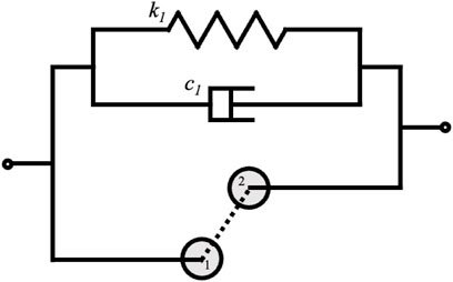
FIGURE 2. Magnetic dipole-viscoelasticity composite mechanics model.
The mechanical performance of MRE materials consists of three components: the matrix, the magnetic particles, and the interaction between the magnetic particles and the matrix. Therefore, changes in the mechanical properties of MRE materials occur when the magnetic particles undergo magnetization under the external magnetic field or when there are changes in their relative positions due to deformation of the material. The mechanisms by which external magnetic fields and strain amplitudes affect the mechanical behavior of MRE materials have been discussed earlier and will not be repeated here. The effect of loading frequency on the interaction between the magnetic particles and the matrix is minimal, so we only need to consider its effect on the matrix and the magnetic particles. At lower loading frequencies, the magnetic particles have sufficient response time to form magnetic chains, so the influence of loading frequency on the mechanical properties of the magnetic particles is minimal. However, the matrix cannot keep up with the loading frequency due to the internal segmental motion, resulting in significant changes in its mechanical properties. Therefore, the changes in the mechanical properties of the matrix dominate at lower loading frequencies. As the loading frequency increases, the formation and breakage time of the magnetic chains decrease, and the magnetic particles become less capable of forming sufficient magnetic chains. Consequently, the mechanical properties of the magnetic particles undergo significant changes, exerting a more pronounced influence on the overall performance of the MRE material.
By analyzing the comprehensive mechanical model established in this study, it is found that the overall stiffness of MRE materials is composed of the stiffness of the matrix and the magnetorheological stiffness of the magnetic particles. Similarly, the overall damping of the material is composed of the damping of the matrix and the magnetorheological damping of the magnetic particles. Therefore, the mechanical behavior of MRE materials can be described using four parameters. Hence, the expression for the mechanical model of MRE materials established in this study is denoted as
where
3 Experiment
3.1 Materials and methods
3.1.1 Preparation of samples
The MRE samples were fabricated with carbonyl iron particles (Type CN, BASF Co., Germany), Polydimethylsiloxane, and curing agent (Sylgard 184, Dow Corning GmbH, United States).
The preparation process (as shown in Figure 3) is as follows: 100 g of PDMS precursor is added, followed by the addition of 77 g of Carbonyl Iron powder. The mixture is vigorously stirred for 5 min until it is homogeneous. Then, 10 g of curing agent is added, and stirring is continued for 15 min until the mixture is uniform. The mixture is poured into a mold and transferred to a sealed container. Vacuum is applied to the container to remove any air bubbles. The mold is covered with a lid and placed in a thermal-magnetic coupling device (as shown in Figure 4A) at a temperature of 100°C and a uniform magnetic field of 1 T for 15 min for curing. Afterward, the mold is placed in an 80°C oven for an additional 30 min for further curing. Finally, the anisotropic MRE sample can be obtained by removing it from the mold (as shown in Figure 4B).
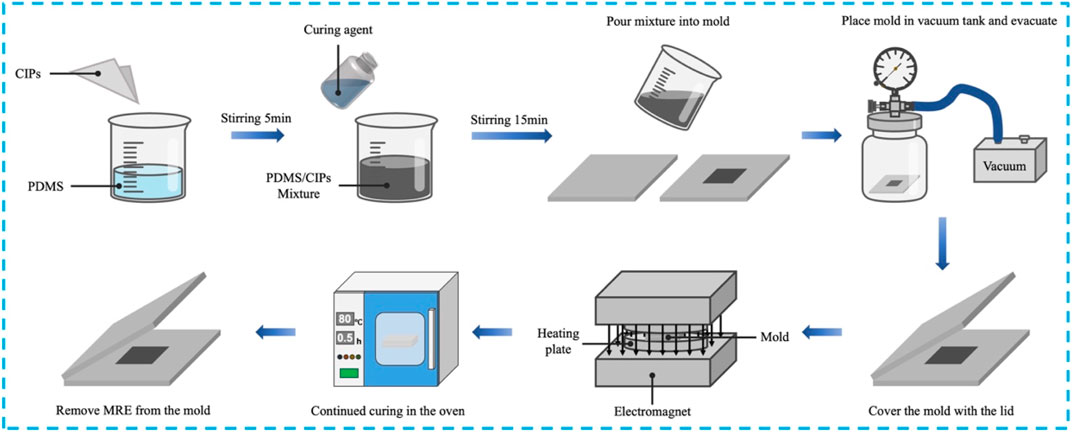
FIGURE 3. Schematic diagram of the preparation process of MRE samples.
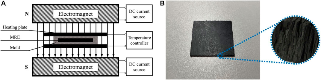
FIGURE 4. (A) Schematic diagram of the thermal-magnetic coupling device; (B) The prepared MRE sample.
Indeed, it can be observed that the MRE sample has solidified and formed a chain-like structure along the direction of the magnetic field.
3.1.2 Performance testing of samples
The instrument used to test the shear mechanical properties of the MRE sample is the Modular Compact Rheometer 302 (Anton Paar Co., Austria, see Supplementary Figure S4). The accessory used during the testing process is the PP20 plate measuring system. The temperature is controlled at 25°C throughout the entire testing process. The testing method is as follows: a circular sample with a thickness of 1 mm and a diameter of 20 mm is placed between two parallel circular plates of the same diameter (20 mm). A controllable and uniform magnetic field is applied between the parallel plates. A pre-load of 5 N is applied to prevent sample slippage during the test. The testing conditions are as follows (as shown in Table 1): a sinusoidal loading mode is used, and the sample is tested at frequencies of 0.1 Hz, 0.5 Hz, 1 Hz, 2 Hz, 3 Hz, and 4 Hz, with strain ranges from 20% to 80% in 20% increments and magnetic fields ranging from 0 to 1,000 mT in 200 mT increments. A total of 168 (= 6*4*7) dynamic shear mechanical property measurements are conducted under different working conditions.
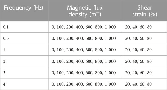
TABLE 1. Test condition of MRE sample.
3.2 Results and discussion
3.2.1 Stress-strain curves of MRE
Figure [see Supplementary Figure S5] shows the hysteresis loops of the MRE obtained at a loading frequency of 4 Hz under different external magnetic fields. It can be observed that the slope of the main diagonal of the MRE hysteresis loop increases with the increase in the external magnetic field. For example, for a shear strain of 20%, the slope of the main diagonal of the hysteresis loop increases by 17.9% from 0 mT to 1,000 mT. The area enclosed by the hysteresis loop also increases, indicating that both the storage modulus and the loss modulus of the MRE increase with the enhancement of the external magnetic field. This indicates that the prepared MRE material exhibits a significant magneto-rheological effect. Furthermore, the shape of the hysteresis loop evolves from elliptical to parallelogram, reflecting the nonlinearity of the prepared MRE material.
Figure [see Supplementary Figure S6] depicts the hysteresis loops of the MRE material measured at different loading frequencies with a magnetic induction of 800 mT. It can be observed that as the loading frequency increases, the slope of the main diagonal of the hysteresis loop decreases continuously, reaching its minimum value at a loading frequency of 4 Hz. The shape of the hysteresis loop evolves towards an elliptical shape with the increase in loading frequency.
Based on Figures 9, 10, it can be observed that the strain amplitude has an influence on the hysteresis loops of the MRE material. As the shear strain increases, the slope of the main diagonal of the hysteresis loop decreases, indicating a decrease in the effective stiffness of the MRE material. Additionally, as the shear strain increases, the area enclosed by the hysteresis loop increases, indicating an increase in the energy dissipation of the MRE material.
3.2.2 Storage modulus of MRE
The storage modulus is calculated as
where
3.2.2.1 The influence of magnetic field
Figure 5 depicts the influence of external magnetic field on the storage modulus of the MRE material under different shear strain amplitudes. The results demonstrate that the storage modulus of the MRE material increases with increasing magnetic induction intensity under any loading frequency and strain amplitude condition. The underlying mechanism behind this phenomenon can be revealed by the proposed magneto-dipole-viscoelastic comprehensive mechanics model in this study. As the external magnetic field increases, the contribution of the magnetic stiffness term K (B) in the magneto-induced stiffness increases. Additionally, the magnetic particles tend to linearize from a wavy structure, leading to an increase in the term K (s) in the magneto-induced stiffness. Consequently, the overall magneto-induced stiffness increases, and the storage modulus follows the same trend, resulting in an increase in the storage modulus of the MRE material with increasing magnetic induction intensity.
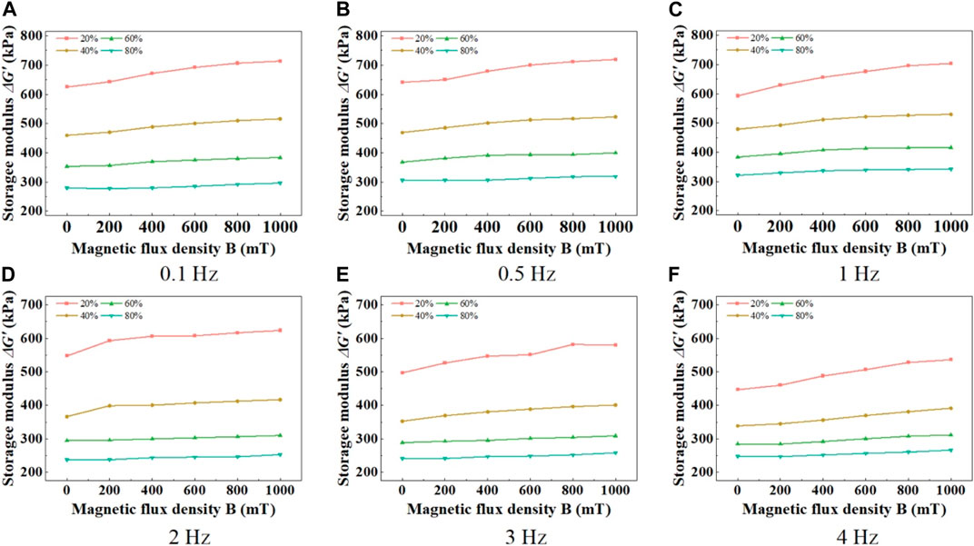
FIGURE 5. Relationship curves between MRE storage modulus and magnetic field under different frequencies. (A) 0.1 Hz, (B) 0.5 Hz, (C) 1 Hz, (D) 2 Hz, (E) 3 Hz, (F) 4 Hz.
However, the dependency of the storage modulus on the magnetic induction intensity decreases with increasing strain amplitude. For instance, at a loading frequency of 4 Hz, as the magnetic induction intensity increases from 0 mT to 1,000 mT, the storage modulus increases from 446.6 kPa to 536.2 kPa (a relative increase of 20.1%) under a shear strain amplitude of 20%. On the other hand, under a shear strain amplitude of 80%, the storage modulus only increases by 7.6% (from 247.6 kPa to 266.4 kPa). This phenomenon can be explained by Eq. 5. According to Eq. 5, the magneto-induced stiffness K consists of the external magnetic field-related term K (B) and the magnetic particle relative position-related term K (t). When the change in the external magnetic field
Furthermore, at a shear strain amplitude of 20% and higher magnetic induction intensity, the storage modulus exhibits magnetic saturation. The saturation magnetic induction intensity of the prepared MRE material is approximately 1,000 mT. For example, at a loading frequency of 1 Hz and a strain amplitude of 20%, the storage modulus increases by 36.3 kPa as the magnetic induction intensity increases from 0 mT to 200 mT. However, when the magnetic induction intensity increases from 800 mT to 1,000 mT, the storage modulus only increases by 7.9 kPa. The magnetic saturation behavior of the material’s storage modulus can be attributed to the nonlinear relationship between the magneto-induced stiffness and the magnetic induction intensity. As the magnetic induction intensity increases, the magnetization intensity of the internal magnetic particles initially grows and then stabilizes. In accordance with Eq. 3, the external magnetic field-related term K (B) tends to stabilize. Additionally, the magnetic particles tend to linearize from a wavy structure, resulting in a decrease in the parameter s and the function K (s) also initially increases and then stabilizes. Consequently, as the magnetic induction intensity increases, the material’s magneto-induced stiffness initially increases and then stabilizes. The storage modulus, following the trend of the magneto-induced stiffness, exhibits apparent magnetic saturation. Moreover, the lower shear strain amplitude exhibits magnetic saturation behavior first, which can be attributed to the closer proximity between the magnetic dipoles at lower strain amplitudes. Under the same magnetic field intensity, the magnetization intensity of the magnetic particles becomes greater, hence resulting in the earlier occurrence of magnetic saturation at lower shear strain amplitudes.
3.2.2.2 The influence of frequency
The loading frequency also has a significant impact on the storage modulus. Figure 6 illustrates the influence of loading frequency on the storage modulus of the MRE material under different external magnetic fields. It can be observed that the effect of loading frequency on the storage modulus is quite complex. With increasing loading frequency, the storage modulus initially increases, reaches a minimum value at 1 Hz, and then rapidly decreases, reaching another minimum value at 4 Hz. For example, at a shear strain amplitude of 60% and a magnetic induction intensity of 1,000 mT, the storage modulus of the MRE material is 387.5 kPa at a frequency of 0.1 Hz. With increasing loading frequency, it reaches the maximum value of 416.2 kPa at 1 Hz and then rapidly decreases to 311.3 kPa at 4 Hz.
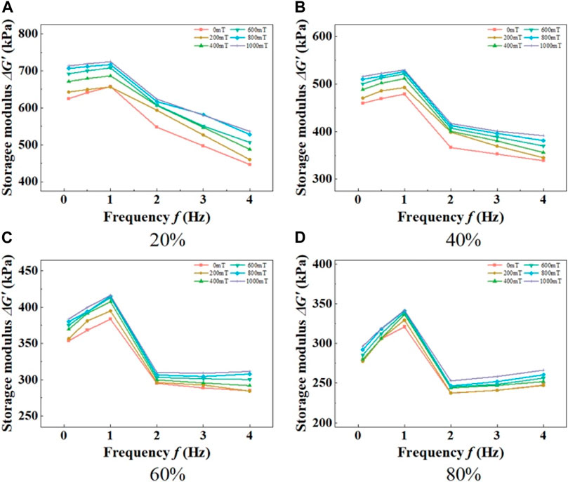
FIGURE 6. Relationship curves between MRE storage modulus and frequency under different shear strain amplitudes. (A) 20%, (B) 40%, (C) 60%, (D) 80%.
The underlying mechanism behind this trend of the storage modulus with loading frequency can be analyzed based on the previous discussion on the influence of loading frequency on the mechanical properties of the material. In the frequency range of 0.1–1 Hz, the mechanical properties of the matrix dominate. As the chain segment motion of the matrix cannot keep up with the speed of external loading, the storage modulus of the material increases with increasing loading frequency. As the loading frequency further increases in the range of 1–4 Hz, the mechanical properties of the magnetic particles become more dominant. With increasing loading frequency, the formation and disruption time of magnetic chains decrease. Consequently, the magnetic particles are unable to form sufficient magnetic chains, leading to a decrease in the storage modulus of the material.
3.2.2.3 The influence of strain
At any loading frequency and magnetic induction intensity, the storage modulus decreases exponentially with increasing strain amplitude, as shown in Figure 7. This trend becomes more pronounced, especially at higher magnetic induction intensities. For example, at a loading frequency of 3 Hz, increasing the strain amplitude from 20% to 80% results in a decrease in the storage modulus by 256 kPa at 0 mT magnetic induction intensity, and a decrease by 322 kPa at 1,000 mT magnetic induction intensity. The phenomenon of decreasing storage modulus with increasing strain amplitude in MRE materials can be explained using Eq. 4. As the shear strain amplitude increases, the K (t) term in the magneto-induced stiffness decreases. Consequently, under the same magnetic field conditions, the magneto-induced stiffness of the MRE material decreases with increasing shear strain amplitude. Since the storage modulus of the material follows the same trend as the magneto-induced stiffness, the storage modulus of the MRE material decreases with increasing strain amplitude. Furthermore, at higher magnetic induction intensities, the decrease in the storage modulus with increasing strain amplitude becomes even more pronounced. The underlying mechanism for this phenomenon can be explained using Eq. 5. The storage modulus of the MRE material consists of two parts: the inherent storage modulus of the material itself and the magnetic field-induced storage modulus dependent on the applied magnetic field. As the strain amplitude increases, the inherent storage modulus of the material decreases. Combined with Eq. 5, when the incremental increase in strain amplitude is the same, the decrease in the K (t) term, which is related to the relative positions of magnetic particles, is also the same. At higher magnetic induction intensities, the value of the K (B) term, which is related to the magnetic field, becomes larger, leading to a greater decrease in the magneto-induced stiffness K and a faster decrease in the magnetic field-induced storage modulus. As a result, the storage modulus of the material decreases more significantly.
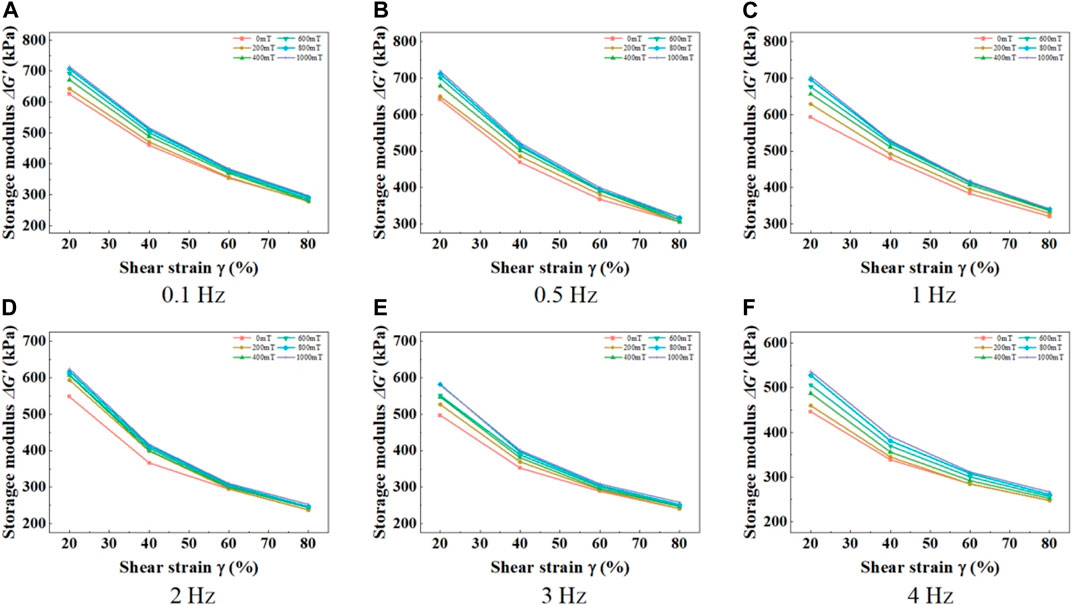
FIGURE 7. Relationship curves between MRE storage modulus and shear strain amplitude under different frequencies. (A) 0.1 Hz, (B) 0.5 Hz, (C) 1 Hz, (D) 2 Hz, (E) 3 Hz, (F) 4 Hz.
3.2.3 Loss modulus of MRE
The loss modulus is calculated as
where
3.2.3.1 The influence of magnetic field
Figure 8 shows the influence of external magnetic field on the loss modulus of MRE at different shear strain amplitudes. The results indicate that the loss modulus of MRE increases rapidly with the increase of magnetic induction intensity under any loading frequency and strain amplitude conditions. This is because the magneto-induced loss modulus of MRE mainly depends on the increased frictional losses between magnetic particles and the matrix. With the increase of the external magnetic field, the magnetic interactions between the magnetic particles intensify, resulting in an increase in the normal pressure between them and the matrix, which leads to an increase in frictional losses. Therefore, the loss modulus of MRE increases with the increase of the external magnetic field. Additionally, it can be observed that the material’s loss modulus exhibits significant magnetic saturation effects at various strain amplitudes and loading frequencies. This is attributed to the nonlinear relationship between the magnetization intensity of magnetic particles within the material and the magnetic induction intensity.
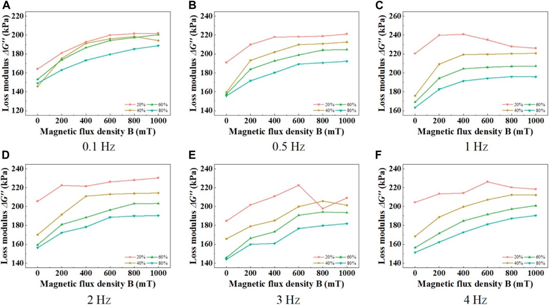
FIGURE 8. Relationship curves between MRE loss modulus and magnetic field under different frequencies. (A) 0.1 Hz, (B) 0.5 Hz, (C) 1 Hz, (D) 2 Hz, (E) 3 Hz, (F) 4 Hz.
3.2.3.2 The influence of frequency
Figure 9 illustrates the influence of loading frequency on the loss modulus of MRE under different external magnetic field conditions. It can be observed that the loss modulus of the material remains nearly constant within the frequency range of 0.1–4 Hz. This is because, within the frequency range of 0.1–1 Hz, the matrix dominates the energy dissipation in the material, and the loading frequency has little effect on the energy dissipation of the matrix. Therefore, the loss modulus remains unchanged within this frequency range. In the frequency range of 1–4 Hz, the mechanical properties of the magnetic particles dominate, while the loading frequency has almost no influence on the magnetic interactions between the particles. Moreover, as analyzed by the mechanical model mentioned earlier, the effect of the loading frequency on the interaction between the matrix and magnetic particles can also be neglected. Therefore, the loss modulus of the material remains constant below 4 Hz.
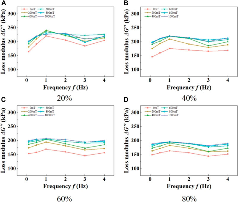
FIGURE 9. Relationship curves between MRE loss modulus and frequency under different shear strain amplitudes. (A) 20%, (B) 40%, (C) 60%, (D) 80%.
3.2.3.3 The influence of strain
Furthermore, as the strain amplitude increases, the loss modulus of MRE material decreases, as shown in Figure 10. This phenomenon can be explained by the magnetic dipole mechanical model established earlier (Figure 1). With the increase in strain amplitude, the distance between magnetic particles is stretched, resulting in a decrease in the magnetic interactions between particles. As a result, the compressive pressure between the magnetic particles and the matrix decreases, leading to a reduction in frictional losses between them and consequently a decrease in the loss modulus.
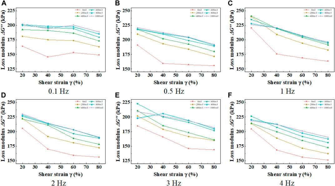
FIGURE 10. Relationship curves between MRE loss modulus and shear strain amplitude under different frequencies. (A) 0.1 Hz, (B) 0.5 Hz, (C) 1 Hz, (D) 2 Hz, (E) 3 Hz, (F) 4 Hz.
3.2.4 Equivalent stiffness of MRE
In order for MRE materials to be practically applied, it is necessary to characterize the macroscopic mechanical properties of components composed of MRE materials, in addition to understanding the microstructural properties such as storage modulus and loss modulus. This includes characterizing the equivalent stiffness and equivalent damping of the MRE-based components.
The equivalent stiffness is a macroscopic representation of the energy storage modulus of a material. The equivalent stiffness of an MRE material is calculated as
3.2.4.1 The influence of magnetic field
The influence of magnetic induction on the equivalent stiffness of the material at different shear strain amplitudes is shown in Figure 11. It can be clearly observed that the equivalent stiffness of the material increases with an increase in magnetic induction. Furthermore, as the shear strain amplitude increases, the dependence of the equivalent stiffness on magnetic induction decreases. For instance, at a loading frequency of 1 Hz, with magnetic induction increasing from 0 mT to 1,000 mT and a shear strain amplitude of 20%, the equivalent stiffness of the material increases from 643.7 kPa to 738.9 kPa (a relative increase of 14.7%). On the other hand, when the shear strain amplitude is 80%, the equivalent stiffness increases from 360.1 kPa to 393.9 kPa (a relative increase of 9.4%). The underlying reason for this phenomenon is similar to that of the storage modulus. With an increase in shear strain amplitude, the distance between magnetic particles is stretched, leading to a weakening effect of magnetic interparticle interactions. This, in turn, results in a reduced dependence of the equivalent stiffness on magnetic induction at the macroscopic level.
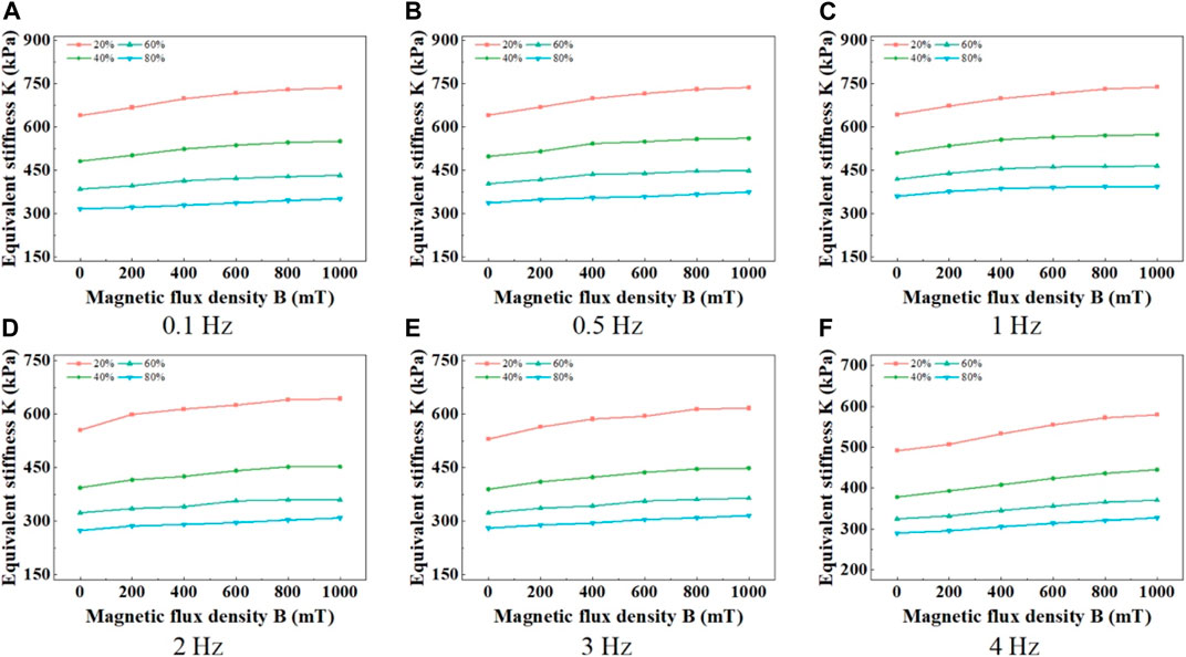
FIGURE 11. Relationship curves between MRE equivalent stiffness and magnetic field under different frequencies. (A) 0.1 Hz, (B) 0.5 Hz, (C) 1 Hz, (D) 2 Hz, (E) 3 Hz, (F) 4 Hz.
Additionally, the material’s equivalent stiffness exhibits a significant magnetic saturation effect with an increase in magnetic induction. This is due to the nonlinear relationship between the magneto-induced stiffness of the MRE material and the magnetic induction. Specifically, as the magnetic induction increases, the magnetization intensity of the internal magnetic particles in the material initially grows and then stabilizes, ultimately reaching magnetic saturation. This magnetic saturation phenomenon becomes particularly pronounced at low shear strain amplitudes. This is because a lower shear strain amplitude corresponds to shorter distances between internal magnetic dipoles in the material. Under the same magnetic field conditions, this results in higher magnetization intensity of the magnetic particles. Consequently, the magnetic saturation effect is more prominent at low shear strain amplitudes.
3.2.4.2 The influence of frequency
The influence of loading frequency on the equivalent stiffness of MRE materials follows a complex pattern, as shown in Figure 12. The equivalent stiffness of the material increases slowly within the range of 0.1–1 Hz. However, once the loading frequency reaches 1 Hz, there is a significant decrease in the equivalent stiffness. The complex trend of the equivalent stiffness with loading frequency can be explained by considering the impact of loading frequency on the mechanical properties of MRE materials, as discussed earlier. Within the loading frequency range of 0.1–1 Hz, the mechanical properties of the material’s matrix play a more dominant role. Due to the inability of the matrix polymer chains to keep up with the movement imposed by external loads, the equivalent stiffness of the material increases with increasing loading frequency. However, as the loading frequency further increases and reaches 1–4 Hz, the mechanical properties of the magnetic particles become dominant. Within this range, the formation and disruption time of magnetic chains in the MRE material shorten. As a result, the magnetic particles become increasingly unable to form sufficient magnetic chains, ultimately leading to a decrease in the material’s equivalent stiffness.
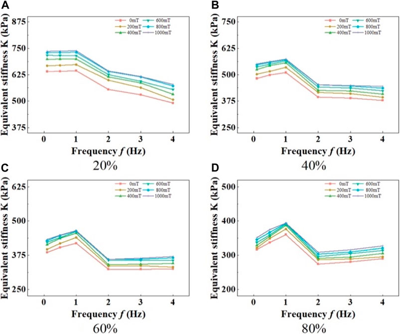
FIGURE 12. Relationship curves between MRE equivalent stiffness and frequency under different shear strain amplitudes. (A) 20%, (B) 40%, (C) 60%, (D) 80%.
3.2.4.3 The influence of strain
The influence of strain amplitude on the equivalent stiffness of MRE materials follows a distinct pattern, where the equivalent stiffness decreases exponentially with increasing strain amplitude, as shown in Figure 13, regardless of the loading frequency and magnetic induction conditions. The underlying mechanism behind this behavior is that as the strain amplitude increases, the distance between magnetic particles increases, leading to a reduction in the magnetic interaction forces between the particles and consequently a decrease in the magneto-induced stiffness. This decrease is manifested at the macroscopic level as a decline in the equivalent stiffness.
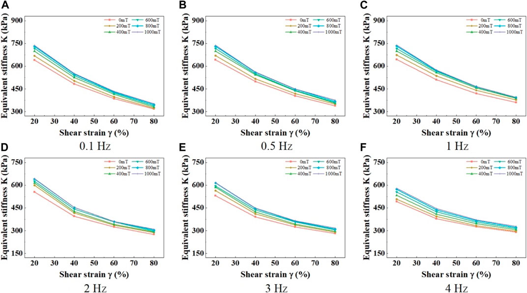
FIGURE 13. Relationship curves between MRE equivalent stiffness and shear strain amplitude under different frequencies. (A) 0.1 Hz, (B) 0.5 Hz, (C) 1 Hz, (D) 2 Hz, (E) 3 Hz, (F) 4 Hz.
3.2.5 Equivalent damping of MRE
For the simple harmonic loading mode, the equivalent damping of the material is calculated as
where
3.2.5.1 The influence of magnetic field
As shown in Figure 14, under any loading frequency and shear strain amplitude conditions, the equivalent damping of MRE increases significantly with the increase of magnetic induction. This phenomenon can be explained using the magnetic dipole mechanical model presented earlier (Figure 1). When the applied magnetic field intensity increases, the magnetic interaction between the magnetic particles increases, leading to an increase in the normal pressure between the magnetic particles and the matrix. This results in increased frictional and energy losses between the magnetic particles and the matrix, leading to an overall increase in the equivalent damping of the MRE material. Additionally, the distance between the magnetic particles decreases with the enhancement of the magnetic field intensity, further contributing to the increase in the equivalent damping of the MRE material.
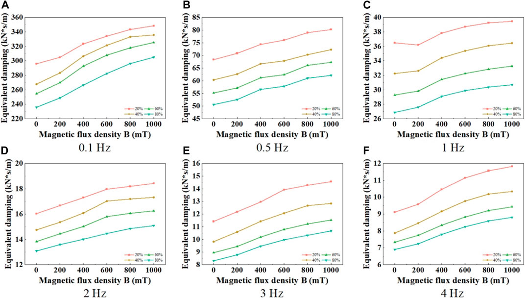
FIGURE 14. Relationship curves between MRE equivalent damping and magnetic field under different frequencies. (A) 0.1 Hz, (B) 0.5 Hz, (C) 1 Hz, (D) 2 Hz, (E) 3 Hz, (F) 4 Hz.
Moreover, it can be observed that MRE materials are more prone to exhibit magnetic saturation, especially at higher loading frequencies, such as 4 Hz. This is because a higher magnetic field intensity requires the magnetic particles in the magnetic chain structure to move a longer distance from the initial position at zero field to the final position. However, as the loading frequency increases, the time available for the formation and disruption of the magnetic chain structure decreases. At this point, the main limiting factor for the internal magnetic particles of the material to move towards the main chain and the sufficient formation of the magnetic chain structure is no longer the applied magnetic field conditions, but the response time. Therefore, as the loading frequency increases, the enhancement of the ideal magnetic chain structure formation due to the increase in magnetic field intensity becomes smaller and smaller. This leads to a reduced influence of the magnetic field intensity on the equivalent damping of the material, ultimately resulting in a greater tendency for MRE materials to exhibit magnetic saturation with higher loading frequencies.
3.2.5.2 The influence of frequency
The influence of loading frequency on the equivalent damping of MRE materials follows a simple and evident pattern. As shown in Figure 15, the equivalent damping of MRE materials decreases rapidly with increasing loading frequency. This is because as the loading frequency increases, the time for the formation and disruption of the magnetic chain structure within the MRE material decreases. Consequently, the MRE material fails to fully establish magnetic chain structures, leading to a decrease in its damping performance.
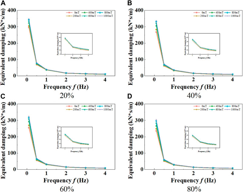
FIGURE 15. Relationship curves between MRE equivalent damping and frequency under different shear strain amplitudes. (A) 20%, (B) 40%, (C) 60%, (D) 80%.
3.2.5.3 The influence of strain
The influence of strain amplitude on the equivalent damping of the material is shown in Figure 16, where the equivalent damping decreases with increasing strain amplitude. This behavior is determined by the viscoelastic properties of the MRE material’s matrix, and it can be attributed to two main factors: the structural changes and magnetic chain formation induced by the magneto-rheological effect, and the nonlinear characteristics of the material under high shear strain conditions. Firstly, as the shear strain amplitude increases, the magnetic particles in the magneto-rheological elastomer align more orderly and form more magnetic chain structures. Due to the increased alignment of magnetic particles, the internal viscous dissipation in the MRE material decreases, leading to a reduction in the material’s damping performance. Secondly, the nonlinear characteristics of the magneto-rheological elastomer also contribute to the decrease in the equivalent damping. The material exhibits linear behavior within a small range of shear strain. However, as the shear strain amplitude increases, the material starts to exhibit nonlinear behavior. In the nonlinear region, the damping characteristics of the material undergo changes. With increasing shear strain, the nonlinear behavior of MRE leads to a decrease in the material’s equivalent damping.
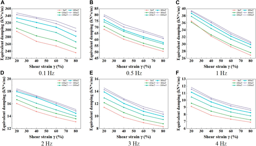
FIGURE 16. Relationship curves between MRE equivalent damping and shear strain amplitude under different frequencies. (A) 0.1 Hz, (B) 0.5 Hz, (C) 1 Hz, (D) 2 Hz, (E) 3 Hz, (F) 4 Hz.
4 Comparison of model predictions and experimental results
During the material testing phase, cyclic shear loading tests were conducted on the MRE material under different applied magnetic fields, loading frequencies, and shear strain amplitudes. Based on the previously established magnetic dipole-viscoelastic comprehensive mechanical model, the parameter values of the mechanical model were determined through parameter identification. Subsequently, the equivalent stiffness and equivalent damping of the prepared MRE material were calculated. Figures [see Supplementary Figures S7–10] present selected representative comparisons between experimental results and model predictions.
By comparing the model predictions with the actual test results, it was found that the established mechanical model can accurately predict the dynamic mechanical properties and magneto-mechanical characteristics of MRE materials. This provides a theoretical foundation for the practical application of MRE materials.
5 Mechanical performance of the energy absorber
5.1 Fabrication of the energy absorber
To improve the utilization of the magnetic field and achieve a higher magnetic flux density, as well as to reduce the lateral deformation of a single layer of MRE, a shear energy absorber was designed and fabricated in this study using a configuration of five layers of steel plates interleaved with four layers of MRE. The assembly is connected using bolts and fixtures at both ends, as shown in Figure 17. The specific dimensions of the internal components are as follows: the MRE layer dimensions are 90*90*5 mm, and the steel plate dimensions are 100*90*5 mm.
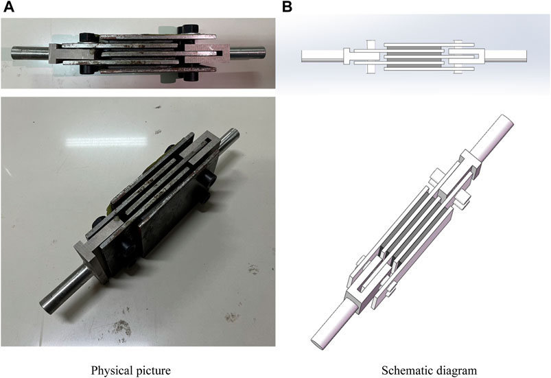
FIGURE 17. Designed and fabricated shear energy dissipator.
5.2 Experimental equipment
The loading equipment used in the experiment is a 250 kN tensile-compression fatigue testing machine (809.25 model, MTS Co., United States). The DC power supply box used is a dual-channel DC power supply box (APS3005S-3D model, GRATTEN Co., CN). The electromagnet used is the YR-P50/27 model electromagnet (CNYRIL Co., CN)
5.3 Performance testing
5.3.1 Experimental methods
This experiment uses sinusoidal cyclic loading to test the mechanical performance of the magneto-rheological shear damper using a displacement control mode. During the test, the shear damper is first placed on the tension-compression fatigue testing machine. Then, the electromagnet is positioned on the brackets at both sides of the shear damper and connected to the DC power supply. The testing system is depicted in Figure [see Supplementary Figures S11].
The shear damper in this study was tested under the following conditions: loading frequencies of 0.1 Hz, 0.3 Hz, 0.5 Hz, 1 Hz, and 2 Hz; shear displacements of 1 mm, 2 mm, 3 mm, and 4 mm; and an applied magnetic field ranging from 0 to 100 mT with increments of 25 mT. A total of 80 test cases were conducted as shown in Table 2.
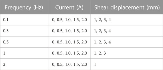
TABLE 2. Test condition of magnetorheological shear energy dissipator.
5.3.2 Experimental results
5.3.2.1 The influence of magnetic field
Figure 18 shows the force-displacement hysteresis curves of the shear damper under different applied magnetic field conditions at a loading frequency of 0.5 Hz. From the graph, it can be observed that the main diagonal slope of the force-displacement hysteresis curve increases with the increase in magnetic induction, indicating that the equivalent stiffness of the shear damper increases with the increasing magnetic induction. This suggests that the shear damper exhibits variable stiffness characteristics. This is attributed to the increase in the equivalent stiffness of the MRE layer in the shear damper with the enhancement of the applied magnetic field. Additionally, the area enclosed by the force-displacement hysteresis curve also increases with the increase in magnetic induction, indicating that the energy dissipation capacity of the shear damper continuously improves. This indicates that the shear damper also exhibits variable damping characteristics.
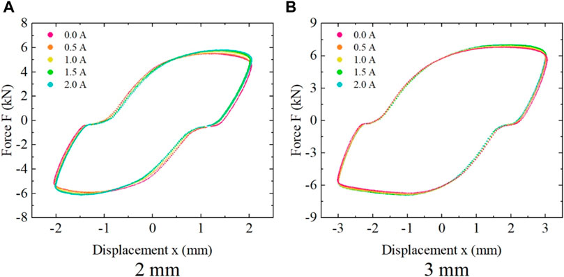
FIGURE 18. Influence of different external magnetic fields on the force-displacement curve at a loading frequency of 0.5 Hz (A) 2 mm, (B) 3 mm.
5.3.2.2 The influence of frequency
Figure 19 shows the force-displacement hysteresis curves of the shear damper obtained from the experimental tests at different loading frequencies with an electrical current intensity of 2.0 A. It can be observed that as the loading frequency increases, the maximum control force of the shear damper initially increases and then rapidly decreases when reaching 2 Hz. The main diagonal slope of the hysteresis curve initially increases with the loading frequency and then rapidly decreases within the range of 1–2 Hz.
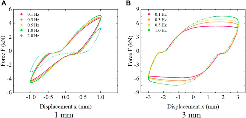
FIGURE 19. Influence of different loading frequencies on the force-displacement curve at a current intensity of 2.0 A. (A) 1 mm, (B) 3 mm.
This behavior can be attributed to the response time of the magnetic particles in the MRE material at lower loading frequencies of 0.1–1 Hz, where they have sufficient time to form adequate magnetic chain structures. At this range of frequencies, the mechanical properties of the magnetic particles are relatively stable. However, the segmental motion of the MRE material’s matrix becomes slower compared to the loading frequency as it increases, causing gradual changes in its mechanical properties. At this point, the matrix’s mechanical properties become more significant in the material. Therefore, the maximum control force and the main diagonal slope of the shear damper increase within the loading frequency range of 0.1–1 Hz.
However, when the loading frequency exceeds 1 Hz, the response time for the magnetic particles to form magnetic chain structures decreases. As a result, the mechanical properties of the magnetic particles rapidly decline, leading to the sharp decrease in the shear damper’s performance beyond 1 Hz of loading frequency.
5.3.2.3 The influence of shear displacement
Figure 20 shows the influence of different shear displacement amplitudes on the force-displacement hysteresis curves of the shear damper at an electrical current intensity of 2.0 A. It can be observed that the maximum output control force of the shear damper increases with the increase in shear deformation. However, the main diagonal slope, which represents the equivalent stiffness, decreases with the increase in shear deformation. The enveloping area of the force-displacement hysteresis curve continuously increases with the increase in shear deformation, indicating an increase in energy dissipation.
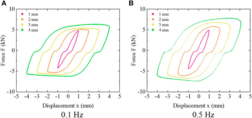
FIGURE 20. Influence of different shear amplitudes on the force-displacement curve at a current intensity of 2.0 A. (A) 0.1 Hz, (B) 0.5 Hz.
Furthermore, it can be noticed that among all the hysteresis curves, there is a “plateau” segment in the force-displacement hysteresis curve when the shear damper transitions from tension to compression, i.e., when the shear force approaches 0 kN. During this segment, the shear displacement of the shear damper increases, but the shear force does not increase. This phenomenon can be attributed to the insufficient precision in the fabrication of the shear damper. Due to the inadequate precision, there exists a gap between the main body of the shear damper and the end fixtures. Therefore, when the shear damper transitions from tension to compression, i.e., when the shear force is near 0 kN, the shear damper exhibits an increase in shear displacement without a corresponding increase in shear force.
5.4 Model validation
The equivalent stiffness of the shear damper can be calculated using Eq. 13 based on the hysteresis curve of the shear damper.
In Eq. 13,
In Figure 21, it can be observed that the equivalent stiffness of the shear energy absorber increases slightly at loading frequencies below 1 Hz. However, when the loading frequency exceeds 1 Hz, the equivalent stiffness of the shear energy absorber decreases rapidly. This phenomenon is attributed to the decrease in the mechanical properties of the magnetic particles in the MRE material, as well as the variation in the mechanical properties of the matrix and magnetic particles in the material.
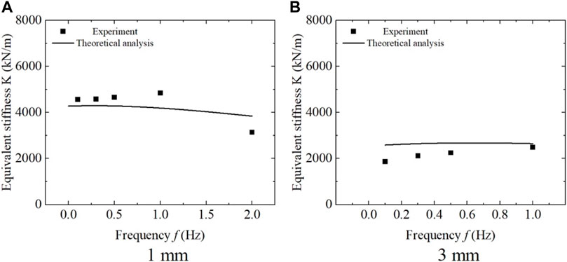
FIGURE 21. Variation of equivalent stiffness with loading frequency at a current intensity of 2.0 A. (A) 1 mm, (B) 3 mm.
Figure 22 shows the relationship between the equivalent stiffness of the energy absorber and the current intensity at a loading frequency of 0.5 Hz. It can be seen that the equivalent stiffness of the shear energy absorber increases with the increase in current intensity. This indicates that the shear energy absorber based on MRE materials possesses real-time controllable and adjustable mechanical properties.
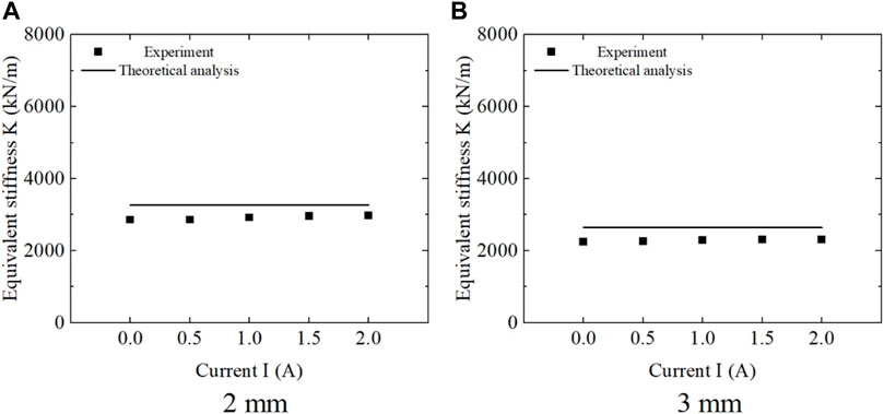
FIGURE 22. Variation of equivalent stiffness with current intensity at a loading frequency of 0.5 Hz (A) 2 mm, (B) 3 mm.
Through the theoretical analysis of the mechanical model established in this paper, the equivalent stiffness of the shear energy dissipator can be obtained, which is calculated as
Where A is area of single material layer, h is thickness of single layer material, N is number of layers of material, and
The calculated values of the shear energy absorber from theoretical analysis are found to be in good agreement with the experimental results, as shown in Figure 22. This validates the correctness of the magnetic dipole-viscoelastic comprehensive mechanical model established in this study. It indicates that the model can accurately describe the mechanical behavior of MRE materials and provide a theoretical basis and guidance for further practical applications of MRE materials.
6 Conclusion
In this paper, a four-parameter magnetic dipole-viscoelastic comprehensive mechanical model was proposed to explain the underlying mechanism of the mechanical properties of MRE under different loading conditions. An MRE material was prepared using carbonyl iron powder and polydimethylsiloxane, and the dynamic mechanical properties of the MRE material under different loading conditions were experimentally tested. The experimental results showed that the storage modulus and loss modulus of the MRE material increased with increasing magnetic induction intensity, exhibiting significant magneto-rheological effects. The storage modulus decreased and then increased with increasing loading frequency, while the loss modulus was almost unaffected by the loading frequency. The storage modulus and loss modulus of the material rapidly decreased with increasing shear strain amplitude. The application of a magnetic induction intensity of 1 T led to a significant increase in the equivalent stiffness and equivalent damping. The mechanical model established in this study was validated by parameter identification using the tested MRE material, demonstrating its ability to characterize and predict the mechanical behavior of the prepared MRE material. Furthermore, a shear energy absorber was designed and fabricated based on the prepared MRE material in this study. Experimental testing of the shear energy absorber confirmed the predicted mechanical properties obtained from the model analysis, showing good agreement with the measured equivalent stiffness. This further validated the accuracy of the magnetic dipole-viscoelastic comprehensive mechanical model established in this paper. The results indicate that the proposed model can accurately describe the mechanical behavior of MRE materials and provide a theoretical basis and guidance for further practical applications of MRE materials.
Data availability statement
The original contributions presented in the study are included in the article/Supplementary Material, further inquiries can be directed to the corresponding author.
Author contributions
All authors listed have made a substantial, direct, and intellectual contribution to the work and approved it for publication.
Funding
Financial supports for this research are provided by the National Natural Science Foundation of China (12002317), the Open Project Program of the CAS Key Laboratory of Mechanical Behavior and Design of Materials (Lmbd 2021-001).
Acknowledgments
These supports are gratefully acknowledged
Conflict of interest
The authors declare that the research was conducted in the absence of any commercial or financial relationships that could be construed as a potential conflict of interest.
Publisher’s note
All claims expressed in this article are solely those of the authors and do not necessarily represent those of their affiliated organizations, or those of the publisher, the editors and the reviewers. Any product that may be evaluated in this article, or claim that may be made by its manufacturer, is not guaranteed or endorsed by the publisher.
Supplementary material
The Supplementary Material for this article can be found online at: https://www.frontiersin.org/articles/10.3389/fmats.2023.1253055/full#supplementary-material
References
Agirre-Olabide, I., and Elejabarrieta, M. (2016). Maximum attenuation variability of isotropic magnetosensitive elastomers. Polym. Test. 54, 104–113. doi:10.1016/j.polymertesting.2016.06.021
Biswal, T., and Rao, L. B. (2016). Analysis of the magnetic field for MR damper working in shear mode. Int. J. Struct. Eng. 7, 48. doi:10.1504/ijstructe.2016.073678
Chen, L., Gong, X., and Li, W. (2007). Microstructures and viscoelastic properties of anisotropic magnetorheological elastomers. Smart Mater. Struct. 16, 2645–2650. doi:10.1088/0964-1726/16/6/069
Choopani, Y., Khajehzadeh, M., and Razfar, M. R. (2022). Experimental investigations into the nano-finishing of Al2024 tubes using the rotational-magnetorheological abrasive flow finishing (R-MRAFF) process. Proc. Institution Mech. Eng. Part E J. Process Mech. Eng. 236, 2545–2557. doi:10.1177/09544089221094999
Dargahi, A., Sedaghati, R., and Rakheja, S. (2019). On the properties of magnetorheological elastomers in shear mode: design, fabrication and characterization. Compos. Part B Eng. 159, 269–283. doi:10.1016/j.compositesb.2018.09.080
Du, X., Yu, M., Fu, J., and Huang, C. (2020). Experimental study on shock control of a vehicle semi-active suspension with magneto-rheological damper. Smart Mater. Struct. 29, 074002. doi:10.1088/1361-665x/ab859e
Ginder, J. M., Nichols, M. E., Elie, L. D., and Clark, S. M. (2000). “Controllable-stiffness components based on magnetorheological elastomers,” in Smart structures and materials 2000: smart structures and integrated systems. (SPIE).
Ginder, J. M., Schlotter, W. F., and Nichols, M. E. (2001). “Magnetorheological elastomers in tunable vibration absorbers,” in Smart structures and materials 2001: damping and isolation (International Society for Optics and Photonics).
Golini, D., Kordonski, W. I., Dumas, P., and Hogan, S. J. (1999). Magnetorheological finishing (MRF) in commercial precision optics manufacturing. Proc. SPIE Intern. Soc. Optic. Eng 3782, 80–91. doi:10.1117/12.369174
Jin, T., Liu, Z., Sun, S., Ren, Z., Deng, L., Yang, B., et al. (2020). Development and evaluation of a versatile semi-active suspension system for high-speed railway vehicles. Mech. Syst. Signal Process. 135, 106338. doi:10.1016/j.ymssp.2019.106338
Ju, B., Tang, R., Zhang, D., Yang, B., Yu, M., Liao, C., et al. (2016). Dynamic mechanical properties of magnetorheological elastomers based on polyurethane matrix. Polym. Compos. 37, 1587–1595. doi:10.1002/pc.23330
Kavlicoglu, B., Liu, Y., Wallis, B., Sahin, H., Mckee, M., and Gordaninejad, F. (2020). Two-way controllable magnetorheological elastomer mount for shock and vibration mitigation. Smart Mater. Struct. 29, 024002. doi:10.1088/1361-665x/ab4223
Morillas, J. R., and De Vicente, J. (2020). Magnetorheology: a review. Soft Matter 16, 9614–9642. doi:10.1039/d0sm01082k
Nam, T. H., Petríková, I., and Marvalová, B. (2020). Experimental characterization and viscoelastic modeling of isotropic and anisotropic magnetorheological elastomers. Polym. Test. 81, 106272. doi:10.1016/j.polymertesting.2019.106272
Ni, Z., Gong, X., Li, J., and Chen, L. (2009). Study on a dynamic stiffness-tuning absorber with squeeze-strain enhanced magnetorheological elastomer. J. Intelligent Material Syst. Struct. 20, 1195–1202. doi:10.1177/1045389x09104790
Rocca, E., and Russo, R. (2021). Development of an innovative torsional vibration damper with magneto-rheological elastomers for vehicle driveline. Cham: Springer International Publishing.
Rudykh, S., and Bertoldi, K. (2013). Stability of anisotropic magnetorheological elastomers in finite deformations: a micromechanical approach. J. Mech. Phys. Solids 61, 949–967. doi:10.1016/j.jmps.2012.12.008
Selvaraj, R., and Ramamoorthy, M. (2020). Experimental and finite element vibration analysis of CNT reinforced MR elastomer sandwich beam. Mech. Based Des. Struct. Mach. 50, 2414–2426. doi:10.1080/15397734.2020.1778487
Sun, S., Tang, X., Li, W., and Du, H. 2017. Advanced vehicle suspension with variable stiffness and damping MR damper. 2017 IEEE International Conference on Mechatronics (ICM). IEEE.
Sun, T., Gong, X., Jiang, W., Li, J., Xu, Z., and Li, W. (2008). Study on the damping properties of magnetorheological elastomers based on cis-polybutadiene rubber. Polym. Test. 27, 520–526. doi:10.1016/j.polymertesting.2008.02.008
Wen, Q., Wang, Y., Feng, J., and Gong, X. (2018). Transient response of magnetorheological elastomers to step magnetic field. Appl. Phys. Lett. 113, 081902. doi:10.1063/1.5048368
Xing, Z., Yu, M., Sun, S., Fu, J., and Li, W. (2015). A hybrid magnetorheological elastomer-fluid (MRE-F) isolation mount: development and experimental validation. Smart Mater. Struct. 25, 015026. doi:10.1088/0964-1726/25/1/015026
Yang, J., Christie, M., Sun, S., Ning, D., Nakano, M., Li, Z., et al. (2020). Integration of an omnidirectional self-powering component to an MRE isolator towards a smart passive isolation system. Mech. Syst. Signal Process. 144, 106853. doi:10.1016/j.ymssp.2020.106853
Yang, J., Sun, S., Tian, T., Li, W., Du, H., Alici, G., et al. (2016). Development of a novel multi-layer MRE isolator for suppression of building vibrations under seismic events. Mech. Syst. signal Process. 70, 811–820. doi:10.1016/j.ymssp.2015.08.022
Yang, J., Sun, S., Zhang, S., and Li, W. (2019). Review of structural control technologies using magnetorheological elastomers. Curr. Smart Mater. 4, 22–28. doi:10.2174/2405465804666190326152207
Keywords: magnetorheological elastomers, stress-strain curve, magnetic dipoleviscoelastic model, equivalent stiffness, equivalent damping
Citation: Huang X, Li L and Ruan X (2023) Theoretical and experimental research on the mechanical properties of magnetorheological elastomers based on PDMS. Front. Mater. 10:1253055. doi: 10.3389/fmats.2023.1253055
Received: 04 July 2023; Accepted: 19 July 2023;
Published: 22 August 2023.
Edited by:
Weihua Li, University of Wollongong, AustraliaReviewed by:
Ying Dan Liu, Yanshan University, ChinaXufeng Dong, Dalian University of Technology, China
Copyright © 2023 Huang, Li and Ruan. This is an open-access article distributed under the terms of the Creative Commons Attribution License (CC BY). The use, distribution or reproduction in other forums is permitted, provided the original author(s) and the copyright owner(s) are credited and that the original publication in this journal is cited, in accordance with accepted academic practice. No use, distribution or reproduction is permitted which does not comply with these terms.
*Correspondence: Xiaohui Ruan, cnhpYW9odWlAenp1LmVkdS5jbg==