 Huifang Yue
 Shichao Liu
 Yong Xin
 Yuanming Li
 Ping Chen
- Nuclear Power Institute of China, Science and Technology on Reactor System Design Technology Laboratory, Chengdu, China
The in-pile performance of SiC cladding with different kinds of end plug were studied. The effect of end plug structure on the mechanical performance of cladding was investigated. The results indicated that obvious stress concentration appeared on the corner between the cladding and end plug for all kinds of cladding. The cladding with a scarf end plug possessed the lowest hoop, axial, and radial stress, which ensured the structural integrity of the fuel element. The cladding with a butted lap end plug suffered rather large axial stress, the maximum valve of which was up to 450 MPa at the end of life, which was higher than the yield strength of SiC ceramics. A scarf end plug can meet the requirements of the cladding, which may be used as an end plug for fuel rods in the future.
1 Introduction
SiC is an attractive material used as a light water reactor (LWR) cladding material due to its excellent features, such as high strength at high temperature, excellent irradiation tolerance, and good resistance of water corrosion (Pint et al., 2013; Katoh et al., 2014; Deck et al., 2015). Compared to monolithic SiC ceramics, continuous SiC fiber-reinforced SiC-matrix composites exhibit pseudo-ductile mechanical behavior, which improves the reliability of SiC cladding (Hasegawa et al., 2000). Many methods have been used to fabricate SiC composite cladding, including nano-infiltration transient eutectic-phase sintering (NITE), chemical vapor infiltration (CVI), precursor impregnation, and pyrolysis (PIP) and melt infiltration (MI) (Shimoda et al., 2009; Kim et al., 2015). SiC cladding possesses two layers, including an inner continuous SiC fiber-reinforced SiC-matrix composite layer and outer monolithic SiC ceramic layers. Layered ceramic composites and stress concentration have been widely investigated (Zhou et al., 2015). The in- and out-pile properties of SiC composite cladding have also been studied, such as the mechanical and thermal properties and irradiation swelling under different neutron fluxes and temperatures (Rohmer et al., 2014; Kim et al., 2015).
Despite the proven advantageous features of SiC composite cladding, its usage in LWRs requires solving the sealing of cladding because of its poor welding properties (Idris et al., 2015; Cozzo and Rahman, 2018). Many experiments and research have been conducted to solve the sealing of cladding. Hybrid preceramic polymer/chemical vapor infiltration was employed to seal SiC composite cladding by Khalifa and coworkers (Khalifa et al., 2015). Four different kinds of end plugs were prepared, and the out-pile performance was studied, including the leak rate and apparent strength of the cladding with an end plug. The scarf and butted scarf possessed high failure loads, which can meet the requirements of the end plug. Joining technology for SiC cladding was investigated by Ishibashi and coworkers (Ishibashi et al., 2016); silicon brazing in local heating technology was optimized, and the shear strength of the joint was tested, with the average shear strength of the joint up to 99 MPa. The in-pile performance of the joint SiC cladding was not studied.
The in-pile performance of SiC cladding was studied by irradiation testing and a simulation method. The effect of irradiation temperature and neutron flux on the thermal and physical properties has been widely studied (Koyanagi et al., 2014; Qiu et al., 2020). SiC exhibits large swelling at low irradiation temperatures. A swelling model was established by Katoh et al., which was employed in this article (Katoh et al., 2013; Katoh et al., 2016). The thermal-mechanical performance of SiC cladding under irradiation conditions has been simulated. For example, Belgacem et al. (2014) used LAPACK software to calculate and compare the thermal-mechanical behavior of SiC composite cladding under steady state, 1-D, and 2-D models. The hoop, axial, and radial stress at BOL and EOL was calculated and the failure probability of SiC cladding was estimated. Avincola et al. (2016) used ADINA software to investigate the mechanical performance of three-layered SiC cladding. The effect of end plug on the performance was also studied; however, the influence of end plug structure was not studied. COMSOL software was employed to investigate the stress field within a spherical electrode particle (Zhou et al., 2013). COMSOL software was used to analyze the in-pile performance of fuel elements in our previous works (Chen et al., 2019; ZhangWu et al., 2021).
In this article, the thermal-mechanical performance of SiC composite cladding with an end plug is simulated by using finite element analysis software coupled with multiple physical fields (COMSOL software). The influence of end plug structure on the performance was studied, and the structure was optimized according to the simulation results.
2 Structure and material properties
2.1 Structure and boundary conditions
Two-layered SiC cladding was established; the inner layer was composed of a SiCf/SiC composite fabricated using the CVI process, which was called the CVI layer. The outer layer was a monolithic SiC ceramic fabricated using the CVD process, which was called the CVD layer. The thickness of the SiC cladding was 1 mm and the thickness of the CVI and CVD layers was 0.8 and 0.2 mm, respectively. The inner diameter of the cladding was 10 mm.
The structure and boundary conditions used in the current simulation are shown in Figure 1. The structure parameters are also shown in Figure 1. A two-dimensional axisymmetric model was established to simulate the in-pile performance of the SiC cladding. An internal pressure (Pi) was induced due to the fission gas release of the fuel, and Pi was defined as the function of burnup. The external pressure (Pe = 15 MPa) was set as constant, which equals the pressure of the coolant.
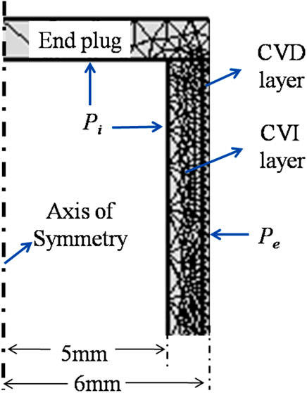
FIGURE 1. Boundary conditions and structure of the simulated model.
Three different kinds of end plug with different structures were designed and their influence on the in-pile performance of the SiC cladding was calculated. The structure and parameters of the end plugs are shown in Figure 2. The end plugs with different structures were labeled as butted, butted lap, and scarf. Three different kinds of end plug have been fabricated previously and the fracture models have been investigated (Khalifa et al., 2015). In this article, the in-pile performance of end plugs with different geometries was simulated.
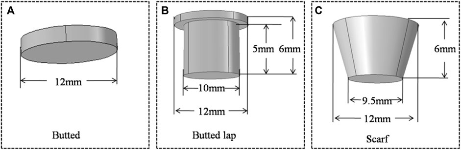
FIGURE 2. Schematic representation of end plugs with different structures, (A) butted, (B) butted lap, (C) scarf.
2.2 Materials properties
COMSOL software provides a computational platform for thermal-mechanical performance analysis of the SiC composite cladding. The solid heat transfer and solid mechanics modules in COMSOL software were used in this article. An irradiation property model for the materials was introduced to simulate the in-pile behavior of the cladding.
The mechanism of irradiation-induced swelling of SiC was different at low and high temperatures. Point defect–induced swelling of SiC was the main reason at relatively low temperatures, while Frank faulted loops were the dominant defects that appeared at higher temperatures and extremely high doses. The irradiation swelling of SiC was a function of temperature and neutron flux. According to the literature, CVI and CVD layers possess the same swelling (Belgacem et al., 2014). The swelling model can be written as follows:
where S is the swelling rate (s−1), Ks is the coefficient of the swelling rate (dpa−2/3), γ is the neutron flux (dpa), and γsc is the characteristic dose for swelling saturation by the negative feedback mechanism (dpa). The swelling of SiC can be obtained from time integration of Eq. 2.
where Ss and γsc are the function of the temperature, and can be expressed as Eqs 3, 4 respectively (Belgacem et al., 2014):
Thermal conductivity affects the temperature profile in the cladding for a given cladding structure; thus, it greatly affects the thermal stress of the cladding and requires accurate assessment. The thermal resistance of SiC cladding can be written as follows (Katoh and Ozawa, 2015):
where R is the thermal resistivity and the subscripts m, gb, U, and id are the matrix, grain boundary, Umklapp (phonon–phonon), and irradiation defect, respectively. The thermal resistivity of SiC can be divided into prior- and post-irradiation parts; thus the thermal conductivity of SiC can be expressed in Eq. 6 (Katoh et al., 2014; Katoh and Ozawa, 2015):
where R0 and Rirr are the thermal resistance (K/W) of the prior- and post-irradiated SiC ceramic, respectively.
CVI and CVD layers possess different thermal resistances before the irradiation process due to their different porosities and microstructures. The expressions for the thermal resistance before irradiation for the CVI and CVD layers can be written as follows in Eqs 7, 8 respectively (Belgacem et al., 2014):
The irradiation-induced thermal resistance of the CVI and CVD layers can be expressed as Eqs 9, 10 (Katoh and Ozawa, 2015):
The thermal conductivity of the CVI and CVD layers can be calculated according to Equation 5.
The CVI and CVD layers possess the same specific heat, and the specific heat of SiC ceramic was 1,000 J/(kg∙K) in this article. The elastic modulus and elastic Poisson ratio of the CVI layer were 250 GPa and 0.18, respectively. The elastic modulus and elastic Poisson ratio of the CVD layer were 450 GPa and 0.21, respectively.
Thermal creep for SiC cladding is ignored in this analysis since the onset of this process (>1,400°C) is well above the temperature range pertinent to cladding operation under nominal LWR conditions. Irradiation creep of SiC is active at low temperatures, which can affect the stress distribution of the SiC cladding. The effect of irradiation creep was considered in the current analysis. According to the literature, the irradiation creep of CVI and CVD layers can be expressed as Eq. 11 (Lee et al., 2017):
where K1 is a temperature-dependent creep coefficient, the value of K1 was 0.4 × 10⁻³¹ n/(m2∙MPa),
The coefficient of thermal expansion (CTE) was considered, which can affect the deformation of the SiC cladding due to a temperature gradient along the thickness direction. The effect of irradiation on the CTE of SiC is negligible, which is a function of temperature. The CET of the two layers can be written as Eq. 12 (Katoh et al., 2014; Katoh and Ozawa, 2015):
3 Results and discussion
3.1 Stress distribution of SiC cladding with different end plugs
The Mises stress distribution of the SiC cladding with different kinds of end plugs at the beginning of life is shown in Figure 3. The maximum stress appeared on the inner and outer surfaces of the cladding for claddings with butted and butted lap end plugs; this phenomenon was different at the end of life, as shown in Figure 4. However, the maximum stress appeared in the junction part, between the end plug and cladding for the scarf plug. The maximum Mises stress of the butted, butted lap, and scarf plug was 138, 135, and 106 MPa, respectively, at the beginning of life. The stress concentration at the corner of the scarf end plug and cladding caused the maximum stress to appear on the corner of this kind of end plug. The corner was set at 90°, and the stress concentration may be relieved by chamfering the corner. The effect of angle on the mechanical performance will be studied in future work.
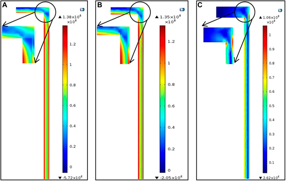
FIGURE 3. Mises distribution of SiC cladding with different end plug structures at the beginning of life (approximately 0.1d): (A) butted, (B) butted lap, and (C) scarf.
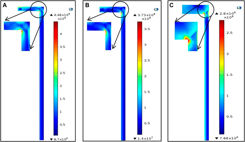
FIGURE 4. Mises distribution of SiC cladding with different end plug structures at the end of life ∼720d: (A) butted, (B) butted lap, and (C) scarf.
Figure 4 shows the Mises stress distribution of SiC cladding when the operation time reached 720 days. SiC cladding possessed low Mises stress, except at the junction part between the end plug and cladding. The gap between the cladding and pellet was set big enough, and the contact between the pellet and cladding was ignored. All the claddings with different end plugs possessed a similar stress distribution. The maximum stress appeared in the junction between the end plug and SiC cladding. Cladding with different kinds of end plugs possessed different maximum Mises stress. The cladding with a scarf end plug suffered the lowest stress and the butted end plug exhibited the highest stress. The maximum Mises stress of the butted, butted lap, and scarf end plug was 448, 373, and 106 MPa, respectively, at the end of life.
3.2 Stress variation with operation time
The stress variation of the SiC cladding with operation time was detected by detecting probes offered by COMSOL software. The detecting probe was set according to the insets shown in Figures 3, 4. The detecting part of the cladding, with different end plugs, is shown in Figure 5, and the probes were labeled for identification. The probes were placed on the contacting corner between the end plug and cladding, and the contacting part between the CVD, CVI, and end plug was selected. These parts suffered larger stress, as shown in Figure 4. The probes in these parts exhibited stress variation with operation time.
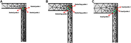
FIGURE 5. Illustration of probes for cladding with different end plugs: (A) butted end plug, (B) butted lap end plug, and (C) scarf end plug.
The hoop stress variation of the SiC cladding with different kinds of end plug with operation time is shown in Figure 6. The detecting probe areas of the cladding are shown in Figure 5. All the claddings possessed a similar current trend. The outer surface of the cladding suffered compressive stress, and tensile stress appeared on the conjoining part (probe 3) between the end plug and cladding; the tensile stress increased quickly at first and the maximum stress appeared at approximately 100 days. The internal pressure of the fuel element increased, which caused the hoop stress to increase. Stress concentration was observed on the conjoining part between the end plug and cladding, which may be caused by the difference in properties between the end plug and cladding. High stress may cause breaking of the cladding. The SiC cladding and end plug swelled at the beginning and saturated at approximately 100 days, as shown in Equation 1. The butted lap end plug possessed the largest hoop stress; the maximum value was up to 125 MPa. The hoop stress of the scarf end plug was much smaller than the others; the maximum hoop stress of the scarf end plug was only approximately 25 MPa. A lower hoop stress can ensure the integrity of the fuel element.
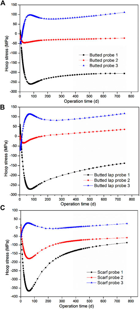
FIGURE 6. Hoop stress variation of SiC cladding with different kinds of end plug with operation time: (A) butted end plug, (B) butted lap end plug, and (C) scarf end plug.
The axial stress variation of the SiC cladding with different kinds of end plugs was detected by detecting probes offered by COMSOL software. The axial stress of the cladding is shown in Figure 7. The axial stress of the claddings with butted and butted lap end plug possessed a similar variation trend; stress concentration appeared on the conjoining part between the cladding and end plug and the axial stress increased rapidly with operation time, with a maximum value of up to 450 MPa at the end of life. The axial stress was produced by the deformation of the cladding and end plug, which was caused by swelling and thermal expansion. The axial stress was much higher than the cladding strength, which may cause breaking of the cladding. The inner connection part between the end plug and cladding, detected by probe 2, suffered tensile axial stress for the claddings with a butted and butted lap end plug. The conjoining part between the cladding and end plug showed stress concentration for the scarfs; however, the tensile axial stress was much smaller than other claddings, and the maximum axial stress of the scarf end plug was approximately 170 MPa. The scarf plug possessed a bevel between the end plug and cladding, which released the stress concentration. The inner connection part between the end plug and cladding suffered compressive stress for the scarf plug. As can be seen, the scarf structure can significantly release the concentration stress of the cladding.
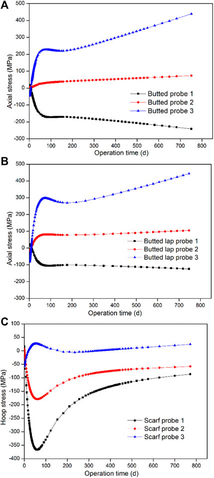
FIGURE 7. Axial stress variation of SiC cladding possessing different kinds of end plug with operation time: (A) butted end plug, (B) butted lap end plug, and (C) scarf end plug.
The radial stress of the cladding with different kinds of end plugs is shown in Figure 8. All the outer surfaces of the cladding exhibited compressive radial stress, and the variation of the compressive stress was small during the operation time. The inner part of the connection between the end plug and cladding for the butted and butted lap plugs suffered tensile stress, as shown in Figure 8A, B. The radial stress of the inner connection between the cladding and end plug increased rapidly with operation time for the cladding with a butted end plug; the maximum value was approximately 40 MPa at the end of life. The maximum value of the butted lap plug was approximately 48 MPa. A large radial stress can de-bond the end plug and cladding. The butted and butted lap end plugs were delaminated from the cladding; this phenomenon has been observed in the literature (Cozzo and Rahman, 2018). The claddings with a butted lap and scarf plug possessed a similar variation trend in the radial stress, where the maximum radial stress appeared on the junction part between the end plug and cladding; the maximum value appeared at approximately 100 days. The maximum radial stress of the scarf plug was much smaller than the butted lap plug. The radial stress was only approximately 10 MPa; the low radial stress ensured the structural integrity of the end plug.
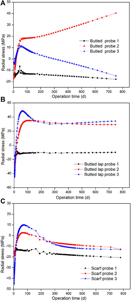
FIGURE 8. Radial stress variation of SiC cladding possessing different kinds of end plug with operation time, (A) Butted end plug, (B) Butted lap end plug, (C) Scarf end plug.
4 Conclusion
The in-pile performance of SiC cladding with different kinds of end plugs was studied using COMSOL software. The end plug structure and parameters were designed, including butted, butted lap, and scarf end plugs, and the effect of end plug structure on the stress distribution and variation was investigated. Stress concentration on the junction between the end plug and cladding was observed. The cladding with a scarf end plug possessed the lowest Mises stress at the beginning and end of life. The maximum hoop stress of the cladding with a scarf plug appeared at approximately 100 days and the maximum value was approximately 25 MPa, which was much lower than the yield strength of the multilayered SiC composites and the end plug. The axial stress of the claddings with butted and butted lap plugs increased with operation time, with a maximum value of up to 450 MPa, which was much higher than the yield strength of the cladding; however, the maximum axial stress of the scarf plug was only approximately 150 MPa. The radial stress of the scarf plug was much lower than the butted and butted lap claddings. To sum up, cladding with a scarf end plug suffered the lowest hoop, axial, and radial stress, and this end plug can be used for SiC cladding. The detailed structural parameters of the scarf end plug, including the intersection angle and height, will be optimized in our future work.
Data availability statement
The original contributions presented in the study are included in the article/Supplementary Material, further inquiries can be directed to the corresponding authors.
Author contributions
HY: Writing–original draft. SL: Writing–review and editing. YX: Conceptualization, Writing–review and editing. YL: Resources, Writing–review and editing. PC: Supervision, Writing–review and editing. XQ: Investigation, Writing–review and editing.
Funding
The author(s) declare financial support was received for the research, authorship, and/or publication of this article. This work was financial supported by the National Natural Science Foundation of China with Grant No. U20B2013, and Sichuan Province Foundation with Grant No.2022NSFC1199, and Young Talents Program of CNNC.
Conflict of interest
The authors declare that the research was conducted in the absence of any commercial or financial relationships that could be construed as a potential conflict of interest.
Publisher’s note
All claims expressed in this article are solely those of the authors and do not necessarily represent those of their affiliated organizations, or those of the publisher, the editors and the reviewers. Any product that may be evaluated in this article, or claim that may be made by its manufacturer, is not guaranteed or endorsed by the publisher.
References
Avincola, V. A., Guenoun, P., and Shirvan, K. (2016). Mechanical performance of SiC three-layer cladding in PWRs. Nucl. Eng. Des. 310, 280–294. doi:10.1016/j.nucengdes.2016.10.008
Belgacem, M., Richet, V., Terrani, K. A., Katoh, Y., and Snead, L. (2014). Thermo-mechanical analysis of LWR SiC/SiC composite cladding. J. Nucl. Mater. 447, 125–142. doi:10.1016/j.jnucmat.2014.01.006
Chen, P., Qiu, S. Z., Liu, S. C., Zhou, Y., Xin, Y., Gao, S., et al. (2019). Preliminary analysis of a fully ceramic microencapsulated fuel thermal–mechanical performance. Mathematics 7, 448–461. doi:10.3390/math7050448
Cozzo, C., and Rahman, S. (2018). SiC cladding thermal conductivity requirements for normal operation and LOCA conditions. Prog. Nucl. Energy 106, 278–283. doi:10.1016/j.pnucene.2018.03.016
Deck, C. P., Jacobsen, G. M., Sheeder, J., Gutierrez, O., Zhang, J., Stone, J., et al. (2015). Characterization of SiC/SiC composites for accident tolerant fuel cladding. J. Nucl. Mater. 466, 667–681. doi:10.1016/j.jnucmat.2015.08.020
Hasegawa, A., Kohyama, A., Jones, R. H., Snead, L., Riccardi, B., and Fenici, P. (2000). Critical issues and current status of SiC/SiC composites for fusion. J. Nucl. Mater. 283, 128–137. doi:10.1016/s0022-3115(00)00374-3
Idris, M. I., Konishi, H., Imai, M., Yoshida, K., and Yano, T. (2015). Neutron irradiation swelling of SiC and SiCf/SiC for advanced nuclear applications. Energy Procedia 71, 328–336. doi:10.1016/j.egypro.2014.11.886
Ishibashi, R., Takamori, Y., and Zhang, X. (2016). Development of joining technology using local heating for SiC fuel cladding. Top. Fuel 2016Boise, 805–813.
Katoh, Y., and Ozawa, K. (2015). A structural model for multi-layered ceramic cylinders and its application to silicon carbide cladding of light water reactor fuel. J. Nucl. Mater. 458, 87–105. doi:10.1016/j.jnucmat.2014.12.013
Katoh, Y., Ozawa, K., Shih, C., Nozawa, T., Shinavski, R. J., Hasegawa, A., et al. (2014). Continuous SiC fiber, CVI SiC matrix composites for nuclear applications: properties and irradiation effects. J. Nucl. Mater. 448, 448–476. doi:10.1016/j.jnucmat.2013.06.040
Katoh, Y., Snead, L. L., Parish, C. M., and Hinoki, T. (2013). Observation and possible mechanism of irradiation induced creep in ceramics. J. Nucl. Mater. 434, 141–151. doi:10.1016/j.jnucmat.2012.11.035
Katoh, Y., Terrani, K., and Koyanagi, T. (2016). Irradiation-high heat flux synergism in silicon carbide based fuel claddings for light water reactors. Top. Fuel 2016 Boise, 823–831.
Khalifa, H. E., Deck, C. P., Gutierrez, O., Jacobsen, G. M., and Back, C. (2015). Fabrication and characterization of joined silicon carbide cylindrical components for nuclear applications. J. Nucl. Mater. 457, 227–240. doi:10.1016/j.jnucmat.2014.11.071
Kim, D., Lee, H., Park, J., and Kim, W. J. (2015). Fabrication and measurement of hoop strength of SiC triplex tube for nuclear fuel cladding applications. J. Nucl. Mater. 458, 29–36. doi:10.1016/j.jnucmat.2014.11.117
Koyanagi, T., Ozawa, K., Hinoki, T., Shimoda, K., and Katoh, Y. (2014). Effects of neutron irradiation on mechanical properties of silicon carbide composites fabricated by nano-infiltration and transient eutectic-phase process. J. Nucl. Mater. 448, 478–486. doi:10.1016/j.jnucmat.2013.10.005
Lee, Y., Hee, C., and Lee, J. (2017). Design optimization of multi-layer Silicon Carbide cladding for light water reactors. Nucl. Eng. Des. 311, 213–223. doi:10.1016/j.nucengdes.2016.11.016
Pint, B. A., Terrani, K. A., Brady, M. P., Cheng, T., and Keiser, J. (2013). High temperature oxidation of fuel cladding candidate materials in steam hydrogen environments. J. Nucl. Mater. 440, 420–427. doi:10.1016/j.jnucmat.2013.05.047
Qiu, B., Wang, J., Deng, Y., Wang, M., Wu, Y., and Qiu, S. (2020). A review on thermo hydraulic and mechanical-physical properties of SiC, FeCrAl and Ti3SiC2 for ATF cladding. Nucl. Eng. Technol. 52, 1–13. doi:10.1016/j.net.2019.07.030
Rohmer, E., Martin, E., and Lorrette, C. (2014). Mechanical properties of SiC/SiC braided tubes for fuel cladding. J. Nucl. Mater. 453, 16–21. doi:10.1016/j.jnucmat.2014.06.035
Shimoda, K., Park, J. S., Hinoki, T., and Kohyama, A. (2009). Microstructural optimization of high-temperature SiC/SiC composites by NITE process. J. Nucl. Mater. 386, 634–638. doi:10.1016/j.jnucmat.2008.12.234
ZhangWu, C. Y., He, Y., Li, Y., Liu, S. C., Zhang, J., et al. (2021). Investigation on thermo-mechanical performance of fully ceramic microencapsulated fuel. J. Nucl. Mater. 556, 153171–153184. doi:10.1016/j.jnucmat.2021.153171
Zhou, W. B., Ai, S. G., Chen, M. J., Zhang, R., Pei, Y., et al. (2015). Preparation and thermodynamic analysis of the porous ZrO2/(ZrO2+Ni) functionally graded bolted joint. Compos. Part B 82, 13–22. doi:10.1016/j.compositesb.2015.07.018
Keywords: thermal mechanical performance, end plug, structure optimize, SiC cladding, COMSOL
Citation: Yue H, Liu S, Xin Y, Li Y, Chen P and Qiu X (2023) In-pile performance of end plug with different structure for SiC cladding. Front. Mater. 10:1321983. doi: 10.3389/fmats.2023.1321983
Received: 15 October 2023; Accepted: 04 December 2023;
Published: 19 December 2023.
Edited by:
Kunal Mondal, Oak Ridge National Laboratory (DOE), United StatesReviewed by:
Wenbin Zhou, University of Dundee, United KingdomArnab Bose, Boehringer Ingelheim, United States
Copyright © 2023 Yue, Liu, Xin, Li, Chen and Qiu. This is an open-access article distributed under the terms of the Creative Commons Attribution License (CC BY). The use, distribution or reproduction in other forums is permitted, provided the original author(s) and the copyright owner(s) are credited and that the original publication in this journal is cited, in accordance with accepted academic practice. No use, distribution or reproduction is permitted which does not comply with these terms.
*Correspondence: Huifang Yue, MTEzMDAwNTc5MkBxcS5jb20=; Shichao Liu, aGl0X2xzY0AxNjMuY29t