 De-jie Li
 Fu-xiang Chen
 Pei-shuai Chen1
- 1CCCC Second Harbour Engineering Co., Ltd., Wuhan, China
- 2Key Laboratory of Ministry of Education for Geomechanics and Embankment Engineering, Hohai University, Nanjing, China
- 3Institute of Geotechnical Research, Hohai University, Nanjing, China
In this study, we investigated the rockfall motion characteristics for varying rock sizes and the structural responses of steel pipes with and without energy dissipation components. Specifically, we conducted rockfall tests under three conditions: (1) an inclined steel pipe, (2) an inclined pipe with a horizontal segment for energy dissipation, and (3) inclined and horizontal steel pipes combined with baffles. The results revealed that the velocity of the rocks of different sizes was similar in the steel pipes without energy dissipation components. The energy dissipation was primarily due to the friction between the rock and the steel pipe, and the friction coefficient was independent of the rock size. The use of horizontal steel pipes effectively dissipated the kinetic energy and reduced the rock velocities by an average of 72.23%. However, as the rock size increased, the velocity increased accordingly, resulting in reduction of the energy dissipation effect. The addition of baffles in the steel pipes increased the energy dissipation during the rockfall and decreased the rock velocity and the impact stress on the horizontal steel pipes. Compared to the single-baffle condition, the average impact stress on the horizontal steel pipes was reduced by 26.5% and 59.6% under the two-baffle and three-baffle conditions, respectively.
1 Introduction
Rockfalls are a common natural phenomenon in mountainous areas (Caviezel et al., 2021; Crosta et al., 2015). The rock is often characterized by high velocities and substantial impact energy, and it is often challenging to accurately predict its trajectory (Briones-Bitar et al., 2020). An uncontrolled rockfall can lead to significant economic losses and personal injuries. Therefore, research on rockfall kinematics, energy dissipation, and rockfall management is of great importance.
Extensive research has been carried out on the motion characteristics of rocks and energy dissipation measures. Nagendran and Ismail (2019) conducted a laboratory experiment on rocks with various sizes falling from different slope angles on different ground surfaces such as soil, concrete, and asphalt materials. It was found that the smaller the rock size was, the steeper the slope was, and the harder the ground surface was, the larger the bounce heights and runout distance were. Liu et al. (2023) identified the rock shape as a key factor affecting the runout distance and proposed an equation for calculating the runout distance based on the rock shape. Asteriou et al. (2012) conducted laboratory and on-site experiments for varying rock masses, impact angles, and velocities, and they found that the impact angle had a significant influence on the rock trajectory. They also proposed a method for calculating the normal coefficients of restitution. Additionally, based o non-site tests, Spadari et al. (2012) concluded that variations in the natural rock properties and the randomness of the impact location greatly affected the test results, even under identical conditions. Considering the eccentricity and directional effects during impact, Dattola et al. (2023) proposed an ellipsoidal block impact model for evaluating the impact force, coefficient of restitution, and trajectory. Yan et al. (2020) simulated four motion modes of rockfalls, i.e., falling, bouncing, rolling, and sliding, using an algorithm for generating arbitrary shapes of falling rocks and terrain, a contact search algorithm, and a bilinear model for contact collision. Wang and Tonon (2011) employed the discrete element method to simulate rock fragmentation caused by impact, and their results showed that the fragmentation was significantly influenced by the impact velocity, incident angle, internal cracks, and ground stiffness. Giacomini et al. (2009) concluded that the impact angle plays a key role in schistose rock fragmentation based on the results of 20 rockfall tests. Dorren et al. (2006) studied the energy dissipation effect of forested slopes on rockfalls and developed a slope surface quantification and modeling method. De Blasio (2014) proposed a model for analyzing the friction and dynamics of rock avalanches on glaciers. Wu et al. (2019) designed an inclined steel rock shed for energy dissipation and studied its dynamic response through laboratory tests and numerical simulations. The above studies have made significant achievements in rockfall research; however, current energy-dissipation structures are complex and costly. Additionally, quantifying the energy dissipation during a rockfall remains challenging due to the complexity of the rock-ground interactions (Matas et al., 2020; Castanon-Jano et al., 2017).
In this study, we investigated the motion characteristics of rockfalls and the effects of energy dissipation approaches. Specifically, we developed an energy dissipation structure consisting of horizontal steel pipes and baffles and conducted rockfall tests under three conditions: (1) an inclined steel pipe, (2) an inclined pipe with a horizontal segment for energy dissipation, and (3) inclined and horizontal steel pipes combined with baffles. The sliding friction coefficient between the rock and the steel pipe was determined, and the effects of the horizontal steel pipes and baffles on the energy dissipation and the mechanical characteristics of the energy dissipation structure were analyzed. The findings of this study provide a reference for rockfall prevention and management on high and steep slopes.
2 Rockfall tests in an inclined steel pipe
In order to obtain the sliding friction coefficient of rocks of different sizes in steel pipes, rocks with varying diameters (10, 15, 20, and 25 cm) were selected for the test (Figure 1). The steel pipe had a diameter of 1 m and a length of 20 m. The steel pipe was lifted using a crane and positioned at 45° from the horizontal plane. The rocks were allowed to fall freely from the top of the steel pipe. After the rock exited the steel pipe, the vertical distance h_1 and horizontal distance h_2 from the rock to the bottom of the steel pipe were measured using an electronic distance measuring device. Since the rocks move freely downward along the vertical direction with an initial velocity, and move at a constant speed along the horizontal direction. The relationship between the initial vertical velocity v_1 of the rocks sliding out of the steel pipe and the vertical distance h_1 is shown in Equation 1, where g is the gravitational acceleration, and t is the time for the rocks to fall from the steel pipe to the ground. The relationship between the initial horizontal velocity v_1 of the rocks sliding out of the steel pipe and h_2 is shown in Equation 2. Since the angle between the steel pipe and the horizontal plane is 45°, the initial vertical velocity v_1 is the same as the initial horizontal velocity v_2. Thus, the velocity v at which different-sized rocks slide out of the bottom opening of the 20 m steel pipe can be calculated as shown in Equation 3. When the rocks slide inside the steel pipe with an initial velocity of 0 m/s and an acceleration of a, the relationship between the acceleration a and the length H of the steel pipe is as shown in Equation 4. The sliding friction coefficient μ of the block stone within the steel pipe can be calculated based on the acceleration a, as shown in Equation 5.
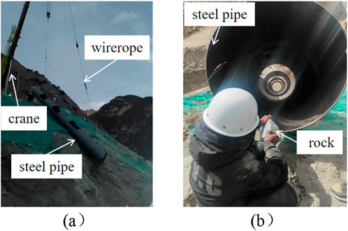
Figure 1. Rockfall test in a steel pipe: (a) Layout, and (b) Rockfall test.
Then, the acceleration a and sliding friction coefficient μ obtained by calculation are shown in Table 1.
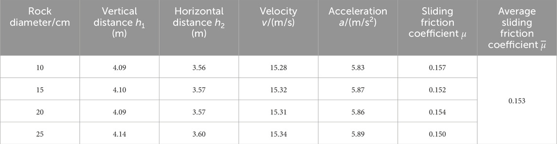
Table 1. Sliding friction coefficient of stone-steel pipe.
The velocities of the 10, 15, 20, and 25 cm rocks at the bottom of the steel pipe were 15.28, 15.32, 15.31, and 15.34 m/s, respectively; and their corresponding sliding friction coefficients were 0.157, 0.152, 0.154, and 0.150, respectively. It can be seen that the sliding friction coefficients of the different rocks were very close, with an average of 0.153.
3 Rockfall test in an inclined pipe with a horizontal segment for energy dissipation
In order to decrease the sliding velocity of the rocks in the steel pipe, a 4 m horizontal steel segment was added at the bottom of the 20 m steel pipe for the purpose of energy dissipation. The angle between the steel pipes was 120° (Figure 2). Then, rockfall tests were carried out using the same samples (i.e., 10, 15, 20, and 25 cm). The average velocities of the rocks at the exit of the horizontal steel pipe were respectively 3.18, 3.79, 4.17, and 4.67 m/s, as shown in Table 2.
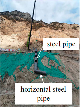
Figure 2. Rockfall test in a steel pipe.
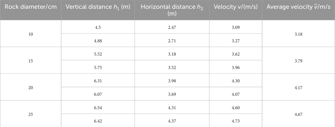
Table 2. Energy dissipation test of 4 m horizontal steel.
Compared with the condition without the horizontal segment, the velocities of the 10, 15, 20, and 25 cm rocks were 79.2%, 75.3%, 72.8% and 69.6% lower, respectively. Thus, the addition of the horizontal steel pipe was effective in terms of the energy dissipation. Compared to the small-sized rocks, due to the larger mass and greater inertia of the large-sized rocks, the impact time on the horizontal section is shorter, and the energy loss is less. After the impact, the speed at which they slide out of the horizontal steel pipe will be greater than that of the small-diameter rocks.
4 Rockfall test in inclined and horizontal steel pipes with baffles
4.1 Test setup
For the case of a 20 m inclined steel pipe and a 4 m horizontal steel pipe, varying numbers of baffles (one, two, and four) were added to the inclined steel pipe, with an angle of 45° between each baffle and the steel pipe. When the rocks strike the baffle in the pipe with the baffle, they will be ejected to the other side of the pipe. Therefore, the baffle can be arranged alternately at certain intervals on both sides of the pipe. During the sliding process of the rocks, most of them are concentrated in the lower part of the pipe. To balance the alternating arrangement and save the baffle material, the shape of the baffle is selected as a quarter circle, with a 1 m diameter and a 1 cm thickness. The stress of the steel pipe was monitored at the end of the horizontal pipe near the intersection of the two segments (Figure 3). In addition, two strain gauges were placed at the lower 1/3 and upper 1/3 of the baffle. The strain gauges on baffles 1, 2, 3, and 4 were labeled id-1 and id-2, id-3 and id-4, id-5 and id-6, and id-7 and id-8, respectively. The odd-numbered strain gauges were located at the bottom and the even-numbered strain gauges were located at the top. One strain gauge, id-9, was placed on the horizontal steel pipe. The positions of the strain gauges for a single baffle are shown in Figure 4a, the layout of the strain gauges along the steel pipe is shown in Figure 4b, and the setup of the on-site test is shown in Figure 4c. The sampling frequency of the strain gauges was 50 Hz, and the exit velocity of the rocks was measured.
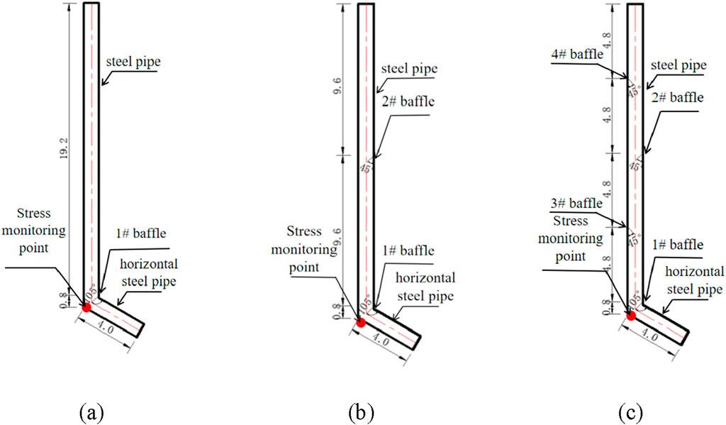
Figure 3. Rockfall test in inclined and horizontal steel pipes with baffles: (a) One baffle, (b) Two baffles, and (c) Four baffles.
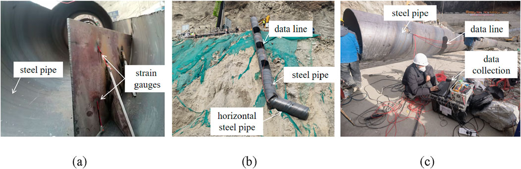
Figure 4. Rockfall test in inclined and horizontal steel pipes with baffles: (a) Stress monitoring points on each baffle, (b) Test layout, and (c) Stress data collection.
4.2 Single-baffle test
For the condition of a single baffle, the structural stresses on the baffle and the horizontal steel pipe are shown in Figure 5. As can be seen, the stress spiked when the rock hit the baffle and the horizontal steel pipe, and the stresses measured at id-1 and id-2 were the same. For the 10, 15, 20, and 25 cm rocks, the maximum impact stresses on the baffle were 11.838, 13.721, 12.826, and 13.402 MPa, respectively, and the maximum impact stresses on the horizontal steel pipe were 6.166, 12.287, 14.105, and 17.099 MPa, respectively. That is, the impact stress increased as the size of the rock increased.
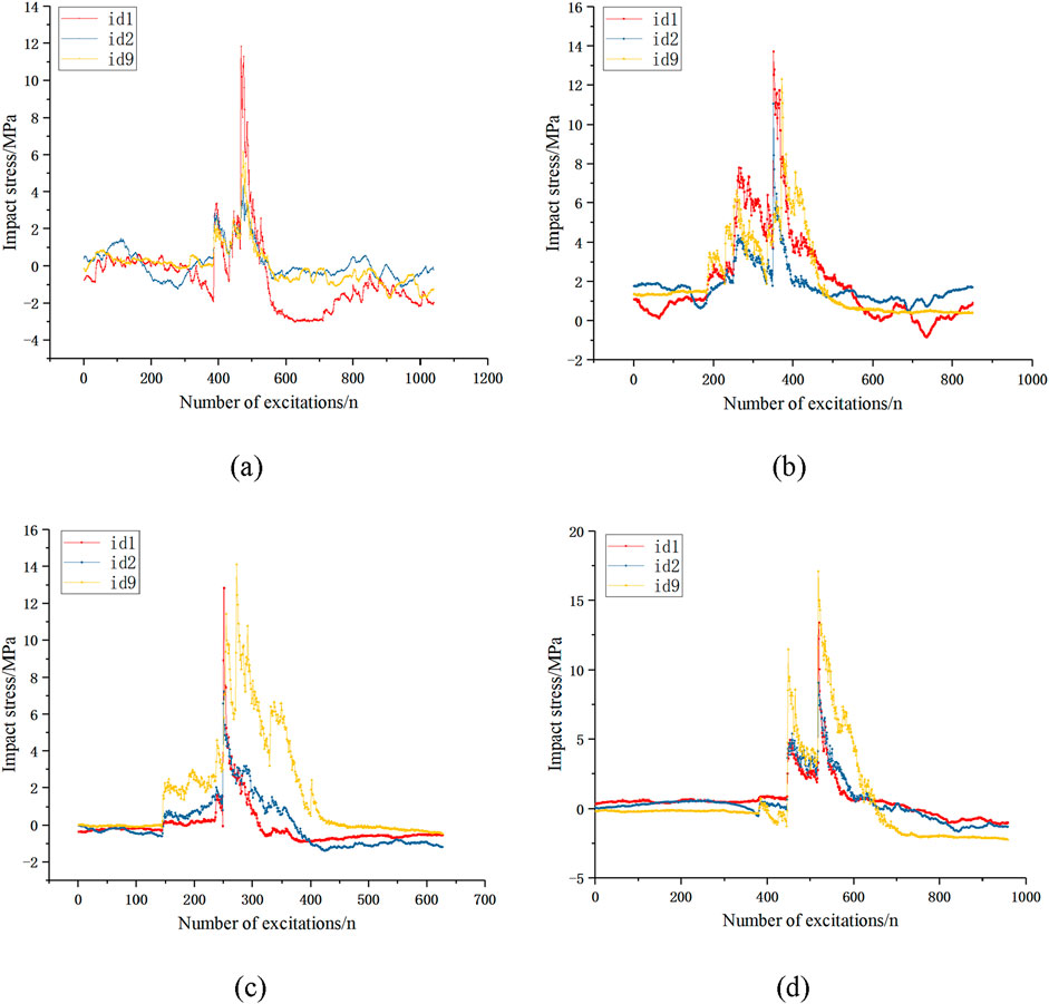
Figure 5. Impact stresses under the single-baffle condition: (a) 10 cm, (b) 15 cm, (c) 20 cm, and (d) 25 cm.
4.3 Two-baffle test
For the condition of two baffles in the inclined pipe, the stresses on the baffle and horizontal steel pipe are shown in Figure 6. As can be seen, for the 10, 15, 20, and 25 cm rocks, the maximum impact stresses on baffle 1 were 9.644, 11.085, 11.7236, and 12.341 MPa, respectively, and the maximum impact stresses on baffle 2 were 6.217, 0.216, 8.488, and 5.583 MPa, respectively. The maximum impact stresses on the horizontal steel pipe were 7.214, 8.604, 9.542, and 11.156 MPa, respectively. In the test, the 15 cm rock did not hit baffle 2, resulting in a small stress (0.216 MPa). Nonetheless, the impact stress still increased with increasing rock size.
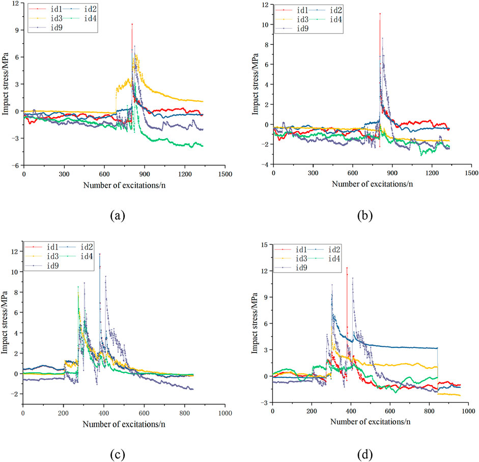
Figure 6. Impact stresses under the two-baffle condition: (a) 10 cm, (b) 15 cm, (c) 20 cm, and (d) 25 cm.
4.4 Four-baffle test
For the condition of four baffles in the inclined pipe, the stresses on the baffle and horizontal steel pipe are shown in Figure 7. As can be seen, the stresses on the different baffles and the horizontal steel pipe were similar, indicating that this setup effectively reduced the impact energy.
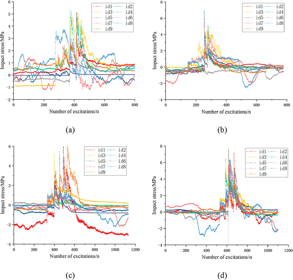
Figure 7. Impact stresses under the four-baffle condition: (a) 10 cm, (b) 15 cm, (c) 20 cm, and (d) 25 cm.
4.5 Comparison of different conditions
The stresses on baffle 1 and horizontal steel pipe under the above three conditions were analyzed. As the rock size increased, the impact stresses on both the baffle and the horizontal steel pipe increased (Figures 8a,b). As the number of baffles increased, the impact stress decreased. Compared to the single-baffle condition, the average impact stresses on baffle 1 and the horizontal steel pipe under the two-baffle condition were 13.5% and 26.5% lower, respectively. For the four-baffle condition, the average impact stresses on baffle 1 and the horizontal steel pipe were 54.1% and 59.6% lower, respectively.
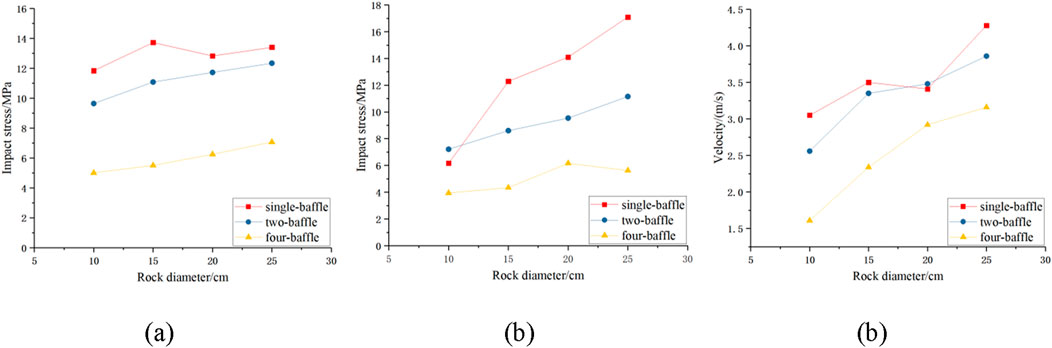
Figure 8. Comparison of different working conditions: (a) Id-1 stress, (b) Id-9 stress, and (c) Exit velocity.
Figure 8c shows the exit velocities of the rocks under the three conditions. It can be seen that the velocity increased with increasing rock size and decreasing number of baffles. The average velocities of the rocks under the single-baffle, two-baffle, and four-baffle conditions were 3.56, 3.32, and 2.51 m/s.
5 Discussion
In the absence of baffles and a horizontal steel pipe, the exit velocities of the rocks of different sizes were similar, this was because the energy dissipation was mainly due to the friction between the rock and the inclined steel pipe, which was independent of the rock size. When a horizontal steel pipe was added, the average velocity of the rocks decreased by 72.23% after impacting the horizontal pipe, suggesting that the horizontal steel pipe had a good energy dissipation effect. Furthermore, when baffles were added to the system, the impact velocity of the rocks was reduced further. Compared with the condition when a horizontal steel pipe was used, the rock velocities were 9.9, 16.0, and 36.5% lower, respectively, under the conditions with one, two, and four baffles. The number of baffles affected the impact stress on the horizontal steel pipe. Compared with the single-baffle condition, the average impact stresses on the horizontal steel pipe under the two-baffle and four-baffle conditions were 26.5% and 59.6% lower, respectively.
The data of each stress monitoring point during the impact of different-sized rocks under different numbers of baffles were summarized, as shown in Table 3. The stress at the lower monitoring points was overall greater than that at the upper monitoring points. The main reason for this is that during the sliding of the rocks in the steel pipe, they mostly fell at the lower part of the pipe, and the lower part directly bears the impact probability is higher. When the number of retaining plates was 1 or 2, and the spacing between the retaining plates was 19.2 m or 9.6 m respectively, the impact force of the rock sliding and impacting the retaining plates from top to bottom showed an increasing trend. When the number of retaining plates was 4 and the spacing was 4.8 m, the impact force of the rock sliding on each retaining plate from top to bottom tended to be the same. This indicates that when the spacing between the retaining plates was 4.8 m, the kinetic energy of the rock sliding onto each retaining plate was relatively consistent, and each retaining plate could play a very good energy dissipation role.
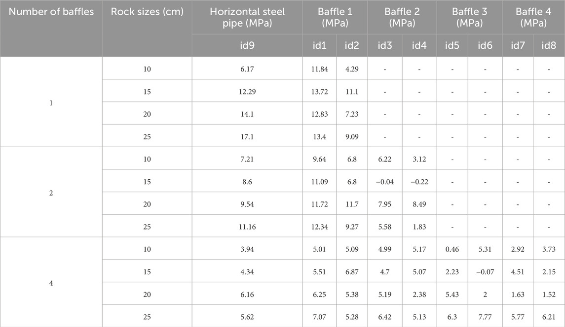
Table 3. Monitoring data of impact stress.
6 Conclusion
In order to investigate the rockfall motion characteristics of varying rock sizes and the structural responses of steel pipes with and without energy dissipation components, we conducted rockfall tests under three conditions: (1) an inclined steel pipe, (2) an inclined pipe with a horizontal segment for energy dissipation, and (3) inclined and horizontal steel pipes combined with baffles. The following conclusions were obtained through the tests.
(1) The velocities of the 10, 15, 20, and 25 cm rocks at the bottom of the steel pipe were 15.28, 15.32, 15.31, and 15.34 m/s, respectively. It can be seen that the sliding friction coefficients of the different rocks were very close, with an average of 0.153.
(2) The horizontal steel pipe effectively reduced the impact stress. However, as the rock size increased, the exit velocity gradually increased, indicating the energy dissipation effect decreased with increasing rock size.
(3) Under different conditions, the impact stresses on the baffles and horizontal steel pipe increased with increasing rock size.
(4) As the number of baffles increased, the exit velocities of the rocks decreased. The average velocities under the conditions with zero, one, two, and four baffles were 3.95, 3.56, 3.32, and 2.51 m/s, respectively.
Data availability statement
The original contributions presented in the study are included in the article/supplementary material, further inquiries can be directed to the corresponding author.
Author contributions
D-jL: Writing – review and editing, Writing – original draft. F-xC: Writing – review and editing. P-sC: Writing – review and editing. JX: Writing – review and editing.
Funding
The author(s) declare that financial support was received for the research and/or publication of this article. This work was supported by the National Natural Science Foundation of China (Grant nos. 41831278 and 51679071).
Conflict of interest
Authors D-jL, F-xC, P-sC, and JX were employed by CCCC Second Harbour Engineering Co., Ltd.
Generative AI statement
The author(s) declare that no Generative AI was used in the creation of this manuscript.
Publisher’s note
All claims expressed in this article are solely those of the authors and do not necessarily represent those of their affiliated organizations, or those of the publisher, the editors and the reviewers. Any product that may be evaluated in this article, or claim that may be made by its manufacturer, is not guaranteed or endorsed by the publisher.
References
Asteriou, P., Saroglou, H., and Tsiambaos, G. (2012). Geotechnical and kinematic parameters affecting the coefficients of restitution for rock fall analysis. Int. J. Rock Mech. Min. Sci. 54, 103–113. doi:10.1016/j.ijrmms.2012.05.029
Briones-Bitar, J., Carrión-Mero, P., Montalván-Burbano, N., and Morante-Carballo, F. (2020). Rockfall research: a bibliometric analysis and future trends. Geosciences 10 (10), 403. doi:10.3390/geosciences10100403
Castanon-Jano, L., Blanco-Fernandez, E., Castro-Fresno, D., and Ballester-Muñoz, F. (2017). Energy dissipating devices in falling rock protection barriers. Rock Mech. Rock Eng. 50, 603–619. doi:10.1007/s00603-016-1130-x
Caviezel, A., Ringenbach, A., Demmel, S. E., Dinneen, C. E., Krebs, N., Bühler, Y., et al. (2021). The relevance of rock shape over mass—implications for rockfall hazard assessments. Nat. Commun. 12 (1), 5546. doi:10.1038/s41467-021-25794-y
Crosta, G. B., Agliardi, F., and Frattini, P. (2015). Key issues in rock fall modeling, hazard and risk assessment for rockfall protection engineering geology for society and territory-volume 2: landslide processes. Springer International Publishing, 43–58.
Dattola, G., di Prisco, C., and Crosta, G. B. (2023). Modeling ellipsoidal block impacts by an advanced rheological model. Rock Mech. Rock Eng. 56 (11), 7997–8018. doi:10.1007/s00603-023-03464-3
De Blasio, F. V. (2014). Friction and dynamics of rock avalanches travelling on glaciers. Geomorphology 213, 88–98. doi:10.1016/j.geomorph.2014.01.001
Dorren, L. K. A., Berger, F., and Putters, U. S. (2006). Real-size experiments and 3-D simulation of rockfall on forested and non-forested slopes. Nat. Hazards Earth Syst. Sci. 6 (1), 145–153. doi:10.5194/nhess-6-145-2006
Giacomini, A., Buzzi, O., Renard, B., and Giani, G. (2009). Experimental studies on fragmentation of rock falls on impact with rock surfaces. Int. J. Rock Mech. Min. Sci. 46 (4), 708–715. doi:10.1016/j.ijrmms.2008.09.007
Liu, F., Hu, N., Sun, G., and Yang, B. (2023). Study on the influence of rock shape on rolling distance. Appl. Sci. 13 (20), 11351. doi:10.3390/app132011351
Matas, G., Lantada, N., Corominas, J., Gili, J., Ruiz-Carulla, R., and Prades, A. (2020). Simulation of full-scale rockfall tests with a fragmentation model. Geosciences 10 (5), 168. doi:10.3390/geosciences10050168
Nagendran, S. K., and Ismail, M. A. M. (2019). Analysis of rockfall hazards based on the effect of rock size and shape. Int. J. Civ. Eng. 17 (12), 1919–1929. doi:10.1007/s40999-019-00418-1
Spadari, M., Giacomini, A., Buzzi, O., Fityus, S., and Giani, G. (2012). In situ rockfall testing in New South Wales, Australia. Int. J. Rock Mech. Min. Sci. 49, 84–93. doi:10.1016/j.ijrmms.2011.11.013
Wang, Y., and Tonon, F. (2011). Discrete element modeling of rock fragmentation upon impact in rock fall analysis. Rock Mech. Rock Eng. 44, 23–35. doi:10.1007/s00603-010-0110-9
Wu, Y., He, S., Li, X., and Wang, D. p. (2019). Dynamic response and optimization of an inclined steel rock shed by the graded energy dissipating method. J. Mt. Sci. 16 (1), 138–152. doi:10.1007/s11629-018-5103-2
Keywords: rockfall, sliding friction, energy dissipation, impact stress, sliding velocity
Citation: Li D-j, Chen F-x, Chen P-s and Xiao J (2025) Energy dissipation during a rockfall and mechanical response of an energy dissipation structure. Front. Mater. 12:1650680. doi: 10.3389/fmats.2025.1650680
Received: 20 June 2025; Accepted: 23 July 2025;
Published: 01 August 2025.
Edited by:
Changtai Zhou, City University of Hong Kong, Hong Kong, SAR ChinaReviewed by:
Mingrui Liu, Shenyang Aerospace University, ChinaHuayong Lv, Shangqiu Normal University, China
Copyright © 2025 Li, Chen, Chen and Xiao. This is an open-access article distributed under the terms of the Creative Commons Attribution License (CC BY). The use, distribution or reproduction in other forums is permitted, provided the original author(s) and the copyright owner(s) are credited and that the original publication in this journal is cited, in accordance with accepted academic practice. No use, distribution or reproduction is permitted which does not comply with these terms.
*Correspondence: De-jie Li, bGlkZWppZWVkdUAxNjMuY29t