- 1Radiation Monitoring Devices, Inc., Watertown, MA, United States
- 2Nuclear Engineering and Radiological Sciences, University of Michigan, Ann Arbor, MI, United States
- 3Lawrence Livermore National Laboratory, Livermore, CA, United States
Thallium bromide (TlBr) is a compound semiconductor with a band gap of 2.68 eV making it ideal for room temperature radiation detection. The high atomic numbers, 81 and 35, and the high density of 7.56 g/cm3 give it excellent gamma-ray stopping power. TlBr is a cubic material that melts congruently at a relatively low temperature (~480°C). These properties make it relatively easy to grow good quality crystals with high yield. As a result of improvements in the purification of TlBr mobility-lifetime product of electrons, μτe, is now on the order of 10−2 cm2/V, which is similar to that of CZT. High μτe enables the fabrication of thicker detectors with good charge collection and energy resolution. The properties of TlBr make it ideal for use in room temperature gamma radiation operation [1]. Single carrier devices such as small pixel arrays [2] and Frisch collar devices [3] which were developed for CZT can also been applied to TlBr. For example, better than 1% FWHM at 662 keV has been obtained for single pixel events with small (e.g., 3 × 3 pixels, 1-mm pitch, 5-mm thick) arrays.
Introduction
Thallium bromide (TlBr) is a compound semiconductor with a band gap of 2.68 eV making it ideal for room temperature detection. The high atomic numbers, 81 and 35, and the high density of 7.56 g/cc give it excellent gamma-ray stopping power [4]. Room temperature resistivity of detector quality TlBr crystals is on the order of 1011 Ohm-cm and electron mobility-lifetime product (μeτe) values are in the 10−3 to 10−2 cm2/V range [5]. TlBr is a cubic material which melts congruently at a relatively low temperature (~480°C) [6]. The cubic structure makes the growth of high quality single crystals relatively easy using conventional melt growth techniques, such as the Bridgeman-Stockbarger technique.
These properties combine to make TlBr a serious competitor to CdTe and CdxZn1−xTe for room temperature radiation detection. The attenuation length of 662 keV gamma rays in TlBr is 1.4 cm, while in CZT it is 2.3 cm [7]. Thus, 1 cm of TlBr has the same stopping efficiency of about 1.6 cm of CZT at 662 keV. As is the case of CZT the mobility-lifetime (μτ) product of electrons is significantly higher than that of holes, and thus unipolar device configurations like small pixel arrays and capacitive Frisch grids CFG), which were originally developed for CZT to improve the energy resolution, also work for TlBr.
Research on TlBr has been ongoing for decades [8–15]. Applications include homeland security, astrophysics [16, 17] and medical x-ray imaging [18, 19]. The use of TlBr, however, had been limited by its relatively poor charge transport properties. Recently. Hitomi et al., demonstrated that multi-pass zone refining of commercially available material improves the charge transport in TlBr [20–22]. Hitomi demonstrated a strong correlation between μτ product and purity. By purifying the TlBr raw material using multiple zone passes they obtained a two-order increase in the μτ-product.
Experimental
Purification and Crystal Growth
To purify the material multiple passes of zone refining were used on commercially available 5N purity TlBr powder (EMD Performance Materials item number 1.893579999) in a horizontal furnace. In the zone refining process the heater was passed over the material at 50 mm/hr for 50–200 passes. The molten zone width was maintained at 20–25 mm.
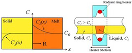
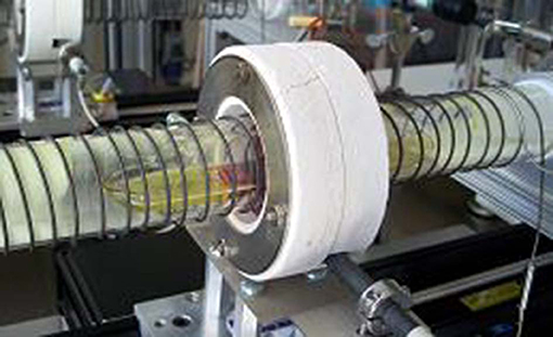
In zone refining, purification is achieved by segregating impurities at a liquid-solid interface Figure 1 shows sketches of the zone refining process. For most materials impurities have differing solubility in the solid and liquid phases. To utilize this technique, a solid-liquid interface is moved from one end to the other along the length of a horizontally oriented ingot. The solubility-difference then “sweeps” impurities in one direction, typically most impurities are more soluble in the melt than in the solid. A small portion (or zone) of the solid host ingot is melted and swept along toward the end of the ampule by the movement of a heater. The impurities migrate, generally with the zone toward one end of the ingot. To increase the efficiency, the process is repeated resulting in highly purified material toward one end (or possibly in the center). Figure 2 shows a TlBr ingot being purified in a zone refiner.
Figure 3 shows a TlBr ingot grown by horizontal zone melting. In this figure, the impurities have been swept to the right end of the ingot, which is clearly darker. The purest material is in the center. The ingot shown underwent 100 zone refining passes. Final crystal growth was performed in the same ampoule using a slow zone melting pass.
GDMS trace element analyses show significant improvement in purity with 100 passes [23]. The concentration of all measured impurities decreased by an order of magnitude or more, some to below the detectable limit. In particular, calcium, aluminum, and chlorine were initially present in high concentrations. Zone refining resulted in a significant reduction in most impurities. Impurities including lithium, sodium, sulfur, calcium, copper, zinc, strontium, and silver were swept to the tail end of the ingot. This is expected for impurities where segregation coefficient k0 <1.
Crystals up to 34 mm in diameter have been grown by this process. Detailed information about the purification and crystal growth has been given in a previous paper [24].
A wire saw with a cutting slurry was used to cut the boule into wafers. These wafers were lapped, polished (final polish with a slurry using 3 micron Al2O3 grit in water) and chemically etched (Br-MeOH or HCl) prior to contact deposition. Several different fabrication methods are used depending on the device configuration. After contact deposition, devices are mounted to carrier boards and wired up.
Device Fabrication
TlBr detectors have been fabricated as planar, pixelated, strip or CFG (capacitive Frisch Grid) devices. Each has advantages depending on the application.
Most of the basic fabrication steps for the various devices are the same: (1) cut wafer from ingot, (2) lap wafer to obtain flat and parallel surfaces, (3) polish the surfaces to be contacted, (4) chemically etch the wafer, (5) deposit (by either thermal or e-beam evaporation) metal electrodes (either Au/Cr or Pt) and (6) mount to detector carrier board and wire up device for testing. Note that the CFG devices require additional steps (e.g., apply insulating collar and metal foil).
Planar devices are simplest to fabricate and read out (Figure 4A). Typically, planar devices fabricated from compound semiconductor material exhibit “hole tailing” due to poor hole mobility. Various approaches can reduce hole tailing such as selecting a short shaping time (i.e., short relative to carrier drift time).
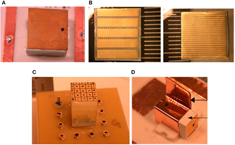
Figure 4. TlBr detector configurations (A) 12 × 12 × 7 mm planar TlBr detector; (B) cathode (2.5 mm pitch) and anode (0.5 mm pitch) electrode strips on a cross strip detector, (C) 13 mm thick pixelated detector (2.0 mm pitch), and (D) 5 × 5 × 12 mm CFG detector.
The crossed strip electrode device structure is basically similar to planar device except that strips make the detector position sensitive (Figure 4B). The strips may be different widths in different pitch on the two sides. The advantage of the structure is you get many pixels with fewer readout channels. The Figure shows a 0.5 mm thick orthogonal strip detector (~12 × 12 mm) with 0.5 mm pitch for the top strips and 2.5 mm pitch for the bottom strips.
Small pixel arrays (i.e., the pixel dimension is small relative to the device thickness) are unipolar charge sensing devices [25] where signal induction occurs primarily when the electrons drift in the vicinity of the anodes and therefore minimize the hole tailing effect [26] (Figure 4C). In addition, the ratio of the cathode-to-anode signal can be used as a depth parameter and signals can be corrected for depth dependence due to electron trapping and variations in weighting potential [27].
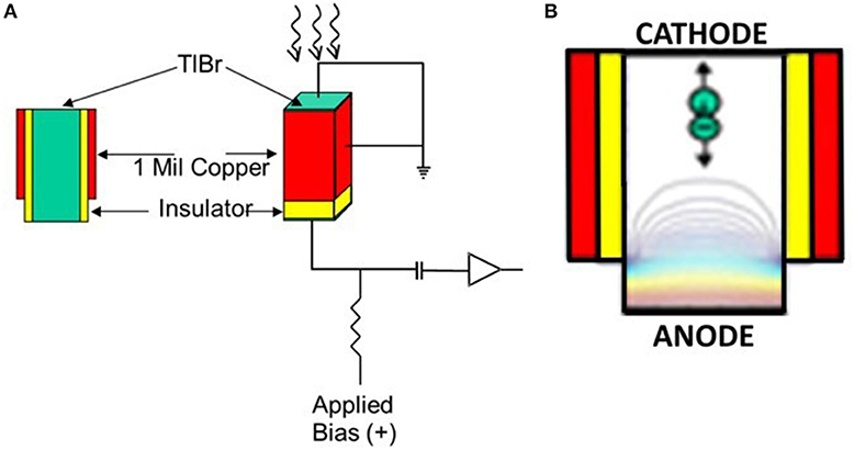
CFG detectors have several advantages. The fabrication is straightforward and reading them out requires only one channel (Figure 4D). Figure 5 shows a schematic of the detector configuration and principle of operation. The crystal is wrapped with thin film of an insulating material, such as Teflon tape. A metal foil, such as copper tape, is then wrapped around the insulator and grounded. This grounded foil has an effect similar to that of a Frisch grid ionization chamber. Positive bias voltage was applied to the anode and the cathode is grounded. Reading out both cathode and anode allows depth correction to be applied.
Results and Discussion
Detector Testing
Planar Detector
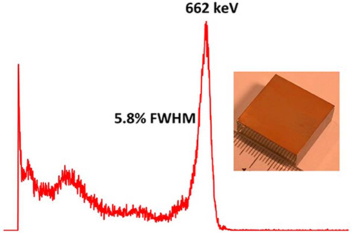
Figure 6 shows a 137Cs spectrum obtained from a 20 × 20 × 8 mm planar detector biased to 700 V and operated at room temperature (24°C). This spectrum was recorded with standard NIM electronics, including charge sensitive preamplifier (Cremat CR110), spectroscopy amplifier (Canberra #2020), and an Amptek 8000A pulse height analyzer. Note that the best energy resolution (5.8% FWHM at 662 keV) was obtained with an amplifier shaping time of 2 μs. Although 2 μs is shorter than the electron transit time across the device, we observed that the energy resolution was optimized at 2 μs. Because of hole tailing longer shaping time broadens the photopeak. At shorter shaping time, the charge collected for the electrons, although less, is more uniform. This results in a lower pulse height, due to the incomplete charge collection, but a better energy resolution.
Frisch Grid Detector
Figure 7 shows a raw 137Cs spectrum obtained from a TlBr capacitive Frisch grid device with dimensions of 5 × 5 × 12 mm and an insulated (with Teflon) copper ring ~10 mm long. The ring was connected to the cathode. The spectrum was recorded at room temperature with standard NIM electronics, including charge sensitive preamplifier (Cremat CR110), spectroscopy amplifier (Canberra #2020), and an Amptek 8000A pulse height analyzer. The bias voltage was 2000 V and the shaping time was 12 μs. The energy resolution (% FWHM at 662 keV) was determined to be 2.2%.
Crossed-Strip Detector
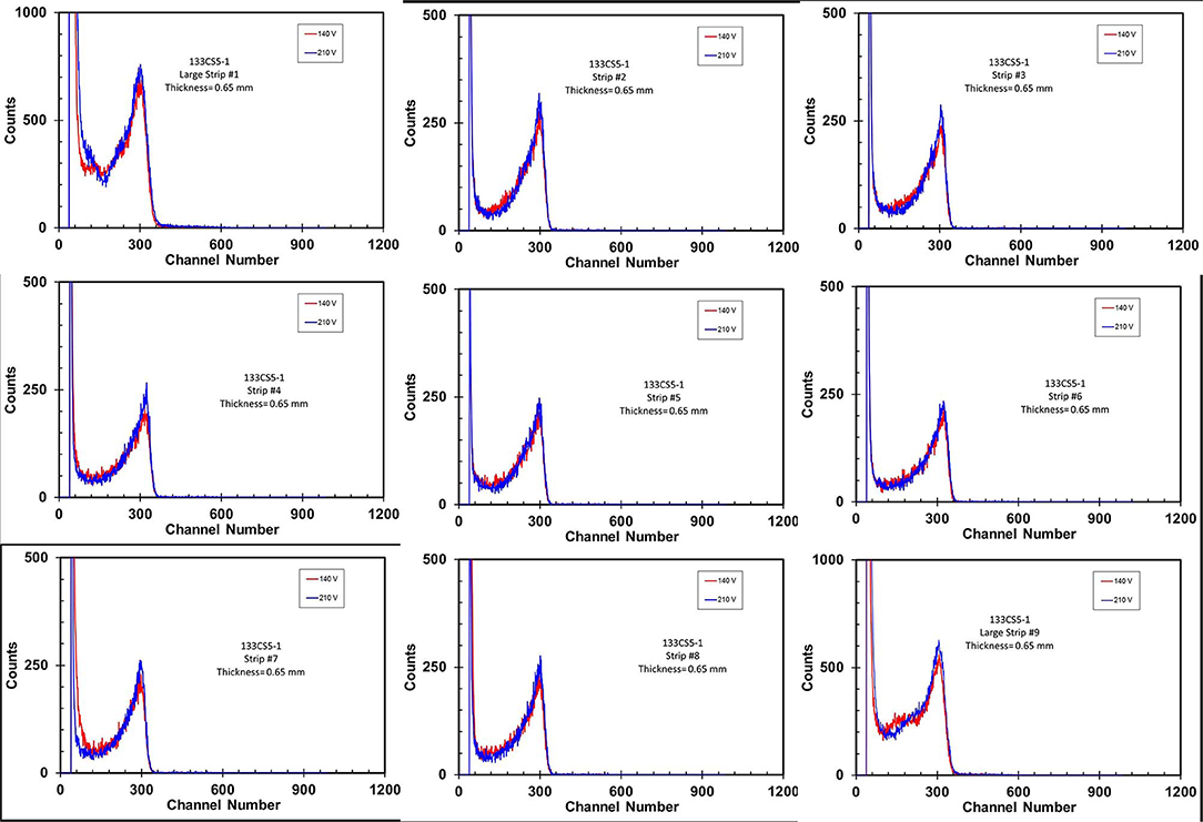
Figure 8 shows 241Am pulse height spectra acquired from nine of the narrow strips of a 0.5 mm thick orthogonal strip detector (~12 × 12 mm) with 0.5 mm pitch for the top strips and 2.5 mm pitch for the bottom strips. The spectra were recorded with standard NIM electronics, including charge sensitive preamplifiers (Cremat CR110), spectroscopy amplifier (Canberra #2020), and an Amptek 8000A pulse height analyzer. The spectra shown in the figure were recorded at two bias voltages (140 and 200 V). Note that the response is fairly similar for each of the strips. Also, the spectra recorded at the two bias voltages basically overlap.
Small Pixel Arrays
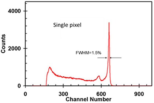
Figure 9 shows a depth corrected 137Cs spectrum from a single pixel of a 13-mm thick, 3 × 3 array with 2 mm pixel pitch. The detector was biased to 2600 V and operated at −18°C. This spectrum was acquired with discrete electronics designed and built at Cremat. Using the cathode-to-anode ratio as a depth parameter, the detector data was separated into 18 depth bins. The photopeaks at each depth were then aligned. The energy resolution after depth correction was determined to be 1.5%.
Figure 10 shows a depth corrected 137Cs spectrum for single-pixel events from a full 9-pixel 5 mm thick 3 × 3 array with 1 mm pitch operated at −20°C and biased to 1000 V. The energy resolution was 0.97%. The data were acquired with eV Products (Cremat Cr110) charge sensitive preamplifiers and GAGE Octopus Compuscope [28].
Larger arrays have been flip chip bonded to substrates for testing. Figure 11 (top row) shows a 5 mm thick 11 × 11 array (1.0 mm pitch) with guard ring and depth corrected 137Cs spectrum from single pixel events from the full array. The depth corrected energy resolution for single pixel events from the full array (excepting pixels from which peaks could not accurately be determined) was determined to be 2.55%. Figure 11 (bottom row, right) shows raw, uncorrected 137Cs spectra for each pixel of the array. Note that the pixels corresponding to the two green boxes were not connected to preamplifier channels. Figure 11 (bottom row, left) shows energy resolution (% FWHM at 662 keV) for the raw spectra. Note “0.00” indicates that the software could not accurately fit the peak. The average raw energy resolution was 2.85% with a standard deviation of 0.88%. The variation in response from pixel to pixel is due to variations in the detector, not the electronics. The array was biased to 1000 V and operated at room temperature. 11 × 11 TlBr arrays were read out with ASIC based electronics developed at the University of Michigan. Signal processing and depth correction codes developed at the University of Michigan were also applied [29].
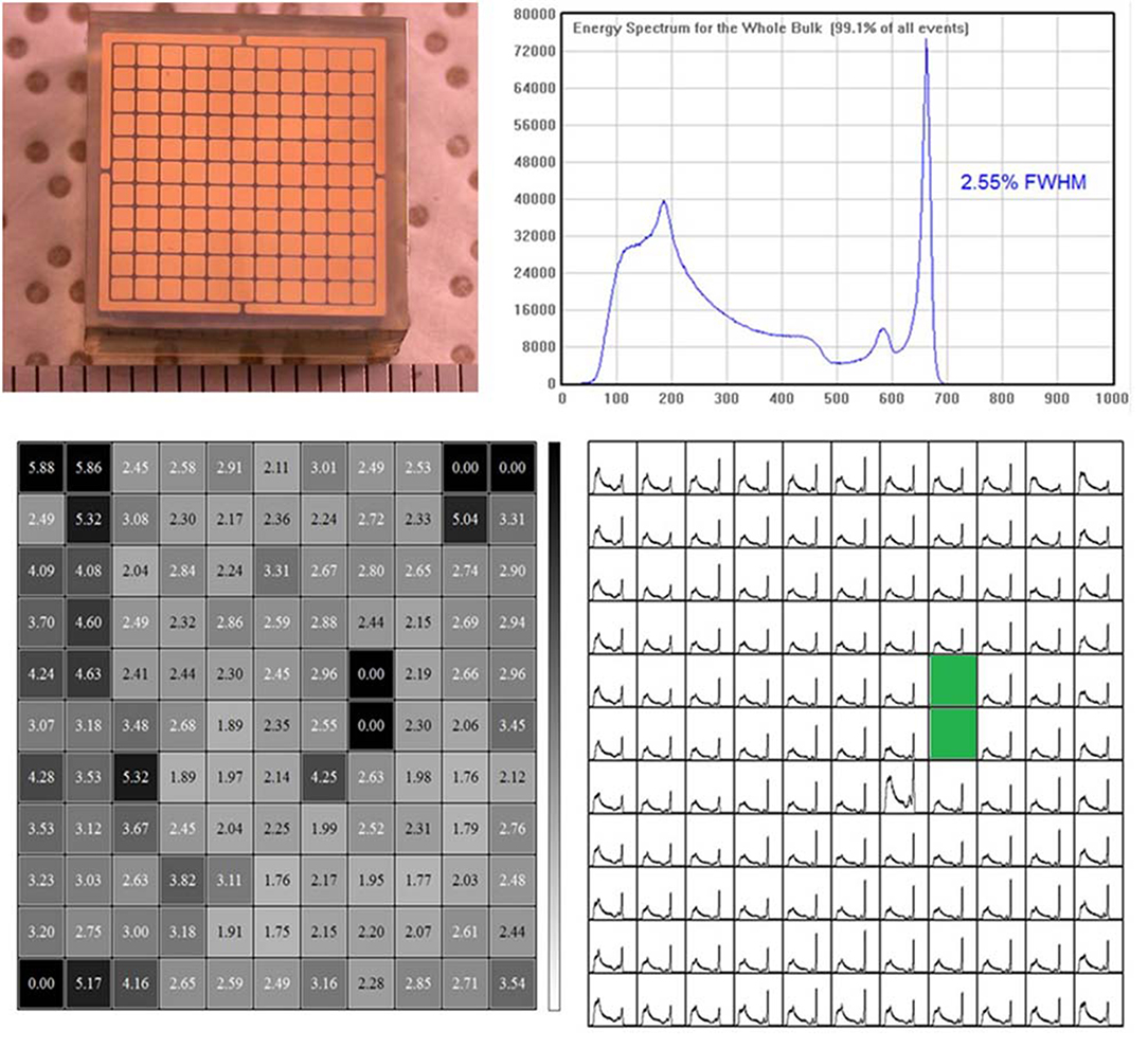
Figure 11. Top left: 11 × 11 array (+ guard ring) (5 mm thick, 1 mm pitch). Top right: depth corrected 137Cs spectrum from single pixel events for the full array. Bottom left: energy resolution (% FWHM at 662 keV) for the raw spectra. Bottom right: raw, uncorrected 137Cs spectra for each pixel of the array.
Detector Stability
Research on the properties of TlBr has shown that ionic conduction contributes to deterioration of TlBr device performance at room temperature [30]. Methods have been developed involving crystal growth, surface processing, and electrode deposition that have enabled TlBr detectors to operate [31–33] for many months under continuous bias. Figure 12 shows photo peak channel and 241Am pulse height spectra vs. time under 100 V bias for a 1 mm thick planar detector. The detector was operated at room temperature (~ 24°C). Note that while the photopeak position is quite constant, the spectral shape does change. It is not clear whether this change is due to bulk or surface properties.

Figure 12. 241Am (60 keV) photo peak channel versus time under bias for a 1 mm thick planar detector under continuous applied electric field of 1 kV/cm.
Dual Mode Semiconductor and Optical Detection
Because of its very high stopping power and good energy resolution TlBr has great potential for use in medical imaging [34]. Unfortunately the charge carrier transit time in TlBr is too long for applications like positron tomography (PET) due to relatively low mobility (~30 cm2/Vsec). Because of its wide band gap, however, TlBr is transparent in the blue. This makes it possible to detect Cherenkov light generated by high energy photoelectrons generated by the positron annihilation 511 keV gamma rays. This light pulse can be used to generate a very fast timing signal. In a recent study a 4 × 4 × 5 mm thick TlBr planar semiconductor detector was modified by coupling a SiPM photodetector to one side of the device to simultaneously measure the Cerenkov radiation with the photodetector and the energy resolution with the semiconductor electronics. The coincidence timing resolution from two coincident annihilation gamma rays was measured to be ~330 ps, much faster than is possible with semiconductors [34]. A dual mode (i.e., electronic and optical) readout combined with a pixelated configuration could provide fast timing, high resolution and position sensitivity.
Applications
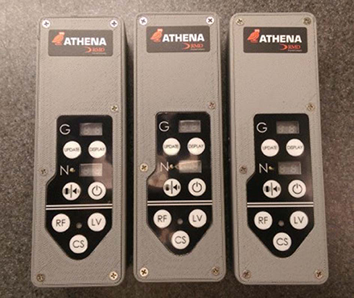
High gamma-ray absorption, photopeak efficiency, and room temperature operation make TlBr an ideal semiconductor detector material for a wide variety of gamma ray detection applications where room temperature operation, good energy resolution and high efficiency are needed. For example, spectroscopic personal radiation dosimeters (SPRDs) and radio-isotope identifying detectors (RIIDs). Figure 13 shows a photograph of a TlBr-based SPRD. Pulse height spectra for various isotopic sources recorded with the SPRD are shown in Figure 14.
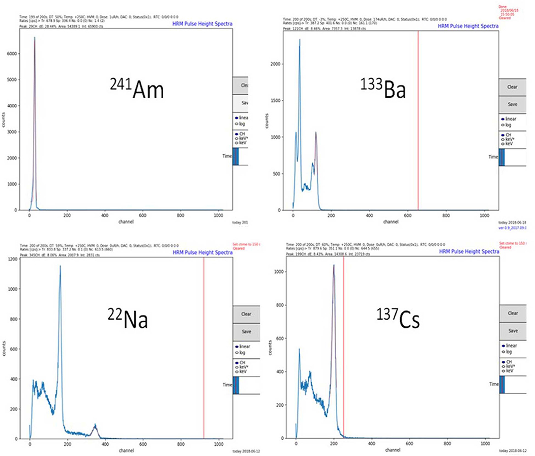
Figure 14. Pulse height spectra recorded with the SPRD. Clockwise from upper left are spectra from 241Am (60 keV), 133Ba (81, 303 356 keV), 137Cs (662 keV), and 22Na (511 and 1.274 keV).
Single photon emission computed tomography (SPECT) is another application ideally suited to TlBr. The absorption length for 140 keV photons is <2 mm compared with ~ 5 mm for CZT leading to reduced parallax errors.
Conclusion
Due to advances in material purification, crystal growth, detector fabrication and signal processing, TlBr spectrometers with better than 1.5% energy resolution at 662 keV at room temperature are now possible. In addition, utilizing Cerenkov photons from interaction of gamma-rays allows fast timing resolution for high energy gamma-rays (>500 keV). TlBr detectors that operate for many months at room temperature under a continuous applied electric field are now possible.
CZT remains the main competing room temperature material for room temperature operation. CZT can have energy resolution better than 1% FWHM at 662 keV using 3D charge collection correction [35]. The detectors are stable at room temperature for long periods of time. The energy resolution of TlBr detectors using single carrier techniques is expected to continue to improve with further research. Even at the present performance TlBr is a superior option in applications where size and stopping power are criteria parameters.
Data Availability Statement
The datasets generated for this study are available on request to the corresponding author.
Author Contributions
HK assisted in fabricating devices and did much of the testing. YO grew TlBr crystals. AK helped design the TlBr CFG devices and fabricated them. LC analyzed and collated the data and wrote most of the article. MS managed several of the TlBr projects reported here and wrote much of the article. KS developed research plans and oversaw the TlBr research. ZH at oversaw the research at University of Michigan. CT, WK, and SO'N assisted ZH in University of Michigan in designing and testing pixel array devices and designing and building the readout ASIC. SP at LLNL oversaw the research and crystal processing procedures and electrode structures, and developed methods for achieving long term stability ES assisted SP in device fabrication and testing.
Funding
This work has been supported by the US Department of Homeland Security, Countering Weapons of Mass Destruction Office, under competitively awarded contracts HSHQDN-16-C-00024 and 70RDND18C00000019. This support does not constitute an express or implied endorsement on the part of the Government.
Conflict of Interest
HK, YO, AK, LC, MS and KS are employees of Radiation Monitoring Devices, Inc.
The remaining authors declare that the research was conducted in the absence of any commercial or financial relationships that could be construed as a potential conflict of interest.
References
1. Smith HM. Characterization of Thallium Bromide (TlBr) for room temperature radiation detectors (dissertation/Doctor of Philosophy). University of California, Berkeley, CA (2013). Available online at: http://digitalassets.lib.berkeley.edu/etd/ucb/text/Smith_berkeley_0028E_13412.pdf
2. O'Neal S, He Z, Leak C, Kim H, Cirignano L, Shah K. Accurate determination of the ionization energy in pixelated TlBr correcting for charge collection efficiency. IEEE Trans Nucl Sci. (2018) 65:950–4. doi: 10.1109/TNS.2018.2804038
3. Hitomi K, ShojibKeizo T, Ishiic K. Advances in TlBr detector development. J Cryst Growth. (2013) 379:93–8. doi: 10.1016/j.jcrysgro.2013.03.002
4. Farrell R, Olschner F, Shah K, Squillante M. Advances in semiconductor photodetectors for scintillators. Nucl Instrum Methods Phys Res A. (1997) 387:194–8. doi: 10.1016/S0168-9002(96)00988-6
5. Kim H, Cirignano L, Churilov A, Ciampi G, Higgins W, Olschner F, et al. Developing larger TlBr detectors – detector performance. IEEE Trans Nucl Sci. (2009) 56:819–23. doi: 10.1109/TNS.2009.2014756
6. Kaye GWC, Laby TH. Tables of Physical and Chemical Constants. 16 th ed. Essex, UK; New York, NY: Langman Scientific and Technical (1995).
7. Berger MJ, Hubbell JH, Seltzer SM, Chang J, Coursey JS, Sukumar R, et al. XCOM: Photon Cross Sections Database, NIST Standard Reference Database 8 (XGAM), NIST Physics Laboratory (2010). Available online at: http://physics.nist.gov/PhysRefData/Xcom/html/xcom1.html
8. Hofstadter R. Thallium halide crystal counter. Phys Rev. (1947) 72:1120–1. doi: 10.1103/PhysRev.72.1120
9. Shah KS, Lund JC, Olschner F, Moy L, Squillante MR. Thallium bromide radiation detectors. IEEE Trans Nucl Sci. (1989) 36:199–202. doi: 10.1109/23.34434
10. Onodera T, Hitomi K, Shoji T, Hiratate Y, Kitaguchi H. Spectroscopic performance of pixellated thallium bromide detectors. IEEE Trans Nucl Sci. (2005) 52:1999–2002. doi: 10.1109/TNS.2005.856876
11. Kozlov V, Leskela M, Vehkama M, Sipila H. Effects of metallisation on TlBr single crystals for detector applications. Nucl Instrum Methods Phys Res A. (2007) 573:212–5. doi: 10.1016/j.nima.2006.10.329
12. Kozlov V, Leskela M, Kemell M, Sipila H. Effects of polishing and etching on TlBr single crystals. Nucl Instrum Methods Phys Res A. (2006) 563:58–61. doi: 10.1016/j.nima.2006.01.065
13. Hitomi K, Onodera T, Shoji T, Hiratate Y, He Z. TlBr gamma-ray spectrometers using depth sensitive single polarity charge sensing technique. IEEE Trans Nucl Sci. (2008) 55:1781–4. doi: 10.1109/TNS.2008.924086
14. Oliveira B, da Costa FE, Kiyohara PK, Hamada MM. Influence of crystalline surface quality on TlBr radiation detector performance. IEEE Trans Nucl Sci. (2005) 52:2058–62. doi: 10.1109/TNS.2005.856788
15. Kim H, Kargar A, Cirignano L, Churilov A, Ciampi G, Higgins W, et al. Recent progress in thallium bromide gamma-ray spectrometer development. IEEE Trans Nucl Sci. (2012) 59:243–8. doi: 10.1109/TNS.2011.2173503
16. Owens BM, Lisjutin I, Peacock A, Sipila H, Zatoloka S. On the development of compound semiconductor thallium bromide detectors for astrophysics. Nucl Instrum Methods Phys Res A. (2001) 458:413–7. doi: 10.1016/S0168-9002(00)00886-X
17. Bavdaz M, Peacock A, Owens A. Future space applications of compound semiconductor X-ray detectors. Nucl Instrum Methods Phys Res A. (2001) 458:123–31. doi: 10.1016/S0168-9002(00)01033-0
18. da Costa FE, Rela PR, Oliveira IB, Pereira MCC, Hamada MM. Surgical gamma probe with TlBr semiconductor for identification of sentinel lymph node. IEEE Trans Nucl Sci. (2006) 53:1403–7. doi: 10.1109/TNS.2006.874472
19. Onodera T, Hitomi K, Shoji T, Hiratate Y. Pixellated thallium bromide detectors for gamma-ray spectroscopy and imaging. Nucl Instrum Methods Phys Res A. (2004) 525:199–204. doi: 10.1016/j.nima.2004.03.046
20. Hitomi K, Murayama T, Shoji T, Suehiro T, Hiratate Y. Improved spectrometric characteristics of thallium bromide nuclear radiation detectors. Nucl Instrum Methods Phys Res. (1998) 428:372–8. doi: 10.1016/S0168-9002(99)00141-2
21. Hitomi K, Muroi O, Matsumoto M, Hirabuki R, Shoji T, Suehiro T, et al. Recent progress in thallium bromide detectors for X- and γ-ray spectroscopy. Nucl Instrum Methods Phys Res A. (2001) 458:365–9. doi: 10.1016/S0168-9002(00)00883-4
22. Hitomi K, Onodera T, Shoji T. Influence of zone purification process on TlBr crystals for radiation detector fabrication. Nucl Instrum Methods Phys Res A. (2007) 579:153–6. doi: 10.1016/j.nima.2007.04.028
23. Churilov A, Ciampi G, Kim H, Cirignano LJ, Higgins WM, Olschner F, et al. Thallium bromide nuclear radiation detector development. IEEE Trans Nucl Sci. (2009) 56:1875–81. doi: 10.1109/TNS.2009.2021424
24. Churilov V, Higgins WM, Ciampi G, Kim H, Cirignano LJ, Olschner F, et al. Purification, crystal growth and detector performance of TlBr. In: Proceedings of the SPIE, 7079. San Diego, CA (2008). doi: 10.1117/12.794838
25. Barrett HH, Eskin JD, Barber HB. Charge transport in arrays of semiconductor gamma-ray detectors. Phys Rev. (1995) 75:156–9. doi: 10.1103/PhysRevLett.75.156
26. Kim H, Cirignano L, Klugerman M, Wong P, Li L, Shah K. Investigation of CZT devices with capacitive frisch grids. Proc SPIE. (2004) 5198:1–8. doi: 10.1117/12.507891
27. O'Neal S, He Z, Leak C. Analysis of high-energy tailing in TlBr detectors. IEEE Trans Nucl Sci. (2018) 65:954–60. doi: 10.1109/TNS.2018.2804165
28. Thrall C, Kaye W, He Z, Kim H, Cirignano L, Shah K. Transient behavior in TlBr Gamma-ray detectors and its analysis using 3-D position sensing. IEEE Trans Nucl Sci. (2013) 60:1162–7. doi: 10.1109/TNS.2012.2220567
29. Zhang F, Herman C, He Z, De Geronimo G, Vernon E, Fried J. Characterization of the H3D ASIC readout system and 6.0 cm3 3-D position sensitive CdZnTe detectors. IEEE Trans Nucl Sci. (2012) 59:236–42. doi: 10.1109/TNS.2011.2175948
30. Vaitkus J, Banys J, Gostilo V, Zatoloka S, Mekys A, Storasta J, et al. Influence of electronic and ionic processes on electrical properties of TlBr crystals. Nucl Instrum Methods Phys Res A. (2005) 546:188–91. doi: 10.1016/j.nima.2005.03.047
31. Kozlov V, Kemell M, Vehkamaki M, Leskela M. Degradation effects in TlBr single crystals under prolonged bias voltage. Nucl Instrum Methods Phys Res A. (2007) 576:10–4. doi: 10.1016/j.nima.2007.01.110
32. Hitomi K, Kikuchi Y, Shoji T, Ishii K. Evaluation of TlBr detectors with Tl electrodes. In: Proceedings of the SPIE. San Diego, CA (2008). doi: 10.1117/12.794381
33. Varley JB, Conway AM, Voss LF, Swanberg E, Graff RT, Nikolic RJ, et al. Effect of chlorination on the TlBr band edges for improved room temperature radiation detectors. IPSS Basic Solid State Phys. (2015) 252:1266–71. doi: 10.1002/pssb.201451662
34. Ariño-Estrada G, Mitche GS, Kim H, Du J, Kwon SI, Cirignano LJ, et al. First Cerenkov charge-induction (CCI) TlBr detector for TOF-PET and proton range verification. Phys Med Biol. (2019) 64:175001. doi: 10.1088/1361-6560/ab35c4
Keywords: Thallium bromide, TlBr, room temperature, semiconductor detector, gamma ray spectroscopy, capacitive Frisch grid, strip detector, small pixel effect
Citation: Kim H, Ogorodnik Y, Kargar A, Cirignano L, Thrall CL, Koehler W, O'Neal SP, He Z, Swanberg E, Payne SA, Squillante MR and Shah K (2020) Thallium Bromide Gamma-Ray Spectrometers and Pixel Arrays. Front. Phys. 8:55. doi: 10.3389/fphy.2020.00055
Received: 05 December 2019; Accepted: 24 February 2020;
Published: 27 March 2020.
Edited by:
Paul Sellin, University of Surrey, United KingdomReviewed by:
Ge Yang, North Carolina State University, United StatesMatthew Charles Veale, United Kingdom Research and Innovation, United Kingdom
Copyright © 2020 Kim, Ogorodnik, Kargar, Cirignano, Thrall, Koehler, O'Neal, He, Swanberg, Payne, Squillante and Shah. This is an open-access article distributed under the terms of the Creative Commons Attribution License (CC BY). The use, distribution or reproduction in other forums is permitted, provided the original author(s) and the copyright owner(s) are credited and that the original publication in this journal is cited, in accordance with accepted academic practice. No use, distribution or reproduction is permitted which does not comply with these terms.
*Correspondence: Michael R. Squillante, bXNxdWlsbGFudGVAcm1kaW5jLmNvbQ==
†Present address: Sean Patrick O'Neal, Lawrence Livermore National Laboratory, Livermore, CA, United States
 Hadong Kim
 Yaroslav Ogorodnik1
 Leonard Cirignano
 Crystal Lynn Thrall
 Stephen A. Payne
 Michael R. Squillante