- 1Special Display and Imaging Technology Innovation Center of Anhui Province, Academy of Opto-electric Technology, Hefei University of Technology, Hefei, China
- 2School of Electronic Science and Applied Physics, Hefei University of Technology, Hefei, China
This study investigated a novel electronically controlled two-dimensional beam-scanning reflective array antenna (reflectarray), which uses nematic liquid crystals. A double-dipole resonance structure is used as the phase-shift unit for the reflectarray for the required phase compensation. The simulation shows that, for about 7 GHz bandwidth of the phase shift range, over 360° can be achieved at the F-band. In addition, a novel wiring scheme is proposed to reduce the adverse effect of the biasing line on the phase-shift performance and simplify the manufacturing process. A simulation of the designed 39 × 39 reflectarray shows that the maximum beam steering range, maximum gain, and side-lobe level at 115 GHz are 20°, 16.55 dBi, and −8.4 dB, respectively.
Introduction
In recent years, millimeter-wave and terahertz reconfigurable reflective array antennas (reflectarrays) have advanced rapidly because of their broad application potentials. These include wireless communication [1], radar systems [2], medical imaging and diagnostics [3], and security inspection [4, 5]. For sub-millimeter and THz application systems, the demand for terahertz functional devices, such as phase shifters [6], resonators [7–9], and antennas [10], is also increasing.
Reflectarrays overcome many of the drawbacks typically associated with individual reflector and planar-phase array antennas. For example, they can maintain high gain with low loss and are relatively simple to fabricate [11]. The phase scheme of conventional reflectarrays includes varying dimensions of reflectarray elements [12]. Once the dimensions of the array and unit cell are determined, both the beam direction and beam shape of the antenna become unchangeable [13]. To still enable beam formation and beam scanning, the reconfigurable reflectarray can be equipped with tunable phase-shifting elements. Furthermore, PIN diodes [14], varactor diodes [15], micro-electromechanical systems (MEMS) [16], and ferroelectric materials [17] are widely used to fabricate phase shifters. However, these are associated with disadvantages such as high loss, the inability to be used for terahertz frequencies, and a high bias-voltage.
Liquid crystals (LCs) are already widely used with terahertz technology and are very suitable for reconfigurable reflectarrays above 60 GHz [18]. Because of their dielectrically adjustable properties, phase shifters [19–21], which are based on LCs, can dynamically control the reflection phase by applying a variable bias-voltage. Furthermore, they can realize a large phase-shift range and wide bandwidth, which allows the LC-based reconfigurable reflectarray to increase the degree of freedom for unit-cell-independent control and wavefront shaping. In addition, the low fabrication cost and low bias-voltage identify them as promising candidates for terahertz reconfigurable reflectarrays [22]. Recently, many LC-based reconfigurable reflectarrays have been reported. For example, a liquid-crystal based reconfigurable antenna was proposed, and gains of 25.1 dB at 78 GHz were obtained [23]. In 2015, liquid crystals, which operate above 100 GHz, were experimentally demonstrated by Perez-Palomino et al. Their study showed that the antenna can generate an electronically steerable beam in one plane across an angular range of 55° [18]. In 2019, a reflectarray, based on liquid crystals and static driving technique in the millimeter-wave band, was proposed. According to a simulation, this reflectarray is capable of two-dimensional beam-scanning [24]. However, most of the reported antennas can only perform one-dimensional (1-D) beam scanning [18, 23]. The reason is the complicated wiring scheme of two-dimensional (2-D) beam scanning antennas, which makes them difficult to fabricate.
This paper describes the application of nematic LCs (NLCs) for electrically controlled reconfigurable reflectarrays ~115 GHz. A simple but effective wiring scheme is proposed, which enables 2-D beam scanning and enables easy fabrication. The proposed reflectarray consists of 39 × 39 double-dipole-patch-based phase-shift cells [25]. Several double dipoles are connected by surrounding rectangular loop bias lines that act as a subarray. Numerical simulation shows that the negative effect of the added rectangular loop bias lines on the phase-shift performance is negligible, and the number of the bias lines decreased by 89% (e.g., for a 3 × 3 phase shift element as a subarray).
Design of a LC-Based Phase Shifter
Figure 1 shows the structure of the phase shifter element. The unit cell consists of two quartz substrates and a sandwiched NLC layer. Both ground and double-dipole resonant structures were printed on the upper surface of the bottom and the lower surfaces of the top quartz substrates, respectively. Both the ground and the patches were made of copper with a conductivity of 5.8 × 10⁷ S/m. The relative dielectric permittivity and loss tangent of quartz are ε = 3.78 and tanδ = 0.002, respectively. To align the NLCs in a state without bias voltage, two thin aligned polyimide layers were spin-coated on the ground and double-dipole patches. The sandwiched NLCs were LC mixtures (HFUT-HB01) with the following characteristic parameters for the F-band: ε⊥ = 2.50, ε∥ = 3.69, and tanδ = 0.02 [26]. Assuming that the device is illuminated by a linear polarization and normal incidence plane wave, the electromagnetic performance of the device has been analyzed and optimized using numerical finite element method (FEM) simulation. The initial value of the patch size was obtained by using the classical formula for the resonant frequency of a patch antenna [27]:
Here, L represents the actual length of the patch, fr represents the resonant frequency, μ0 represents permeability in free space, ε0 represents permittivity in free space, εreff represents the effective dielectric constant of the substrate, and ΔL represents the extended incremental length of the patch. For example: using (1), the actual length of the patch was 713.1 μm at 115 GHz.
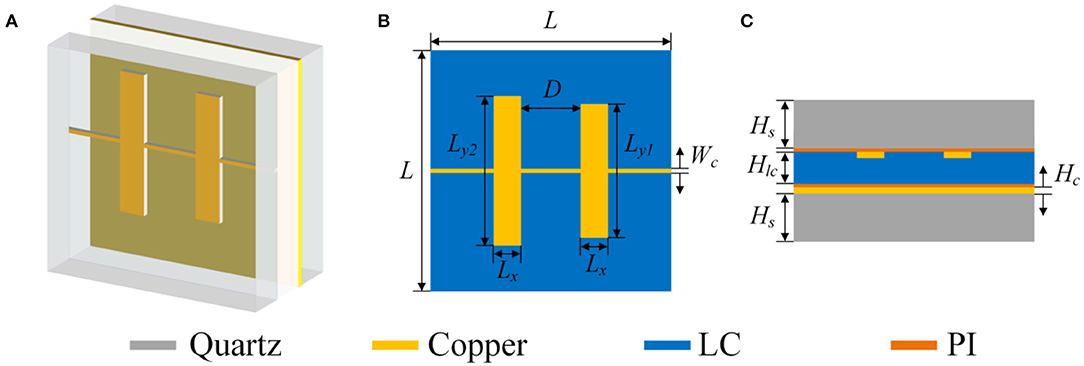
Figure 1. Three-dimensional (3-D) schematic diagram of a phase shifter unit (A). Top view of the unit cell (B). Side view of the unit cell (C).
Other parameters, such as the dipole width and the distance between two dipoles, were adjusted to obtain the required phase range and the frequency shift. The adjustment was made by consecutively and independently changing each parameter. The optimized dimensions for the unit cell are shown in Table 1.
The reflected element consists of two parallel unequal electric dipole patches, and the electric dipole resonance is excited by a linear polarization and normal incidence terahertz plane wave. Figure 2A shows the amplitude vs. frequency for a dielectric permittivity variation from 2.50 to 3.69 and the value change between −1.5 dB and −5.5 dB at 115 GHz. As shown in Figure 2A, the maximum loss is −7.9 dB at 104 GHz, and the minimum loss is −6.4 dB at 123 GHz. In Figure 2B, a phase shift range of 360 was obtained for a 7 GHz bandwidth, which ensures the design of a reconfigurable reflectarray antenna, and the curve showed good linearity. The inset of Figure 2B shows the surface current distribution around double-dipoles at 115 GHz. The largest current exists at the surface of the dipole, phase-shifted at the resonant frequency.
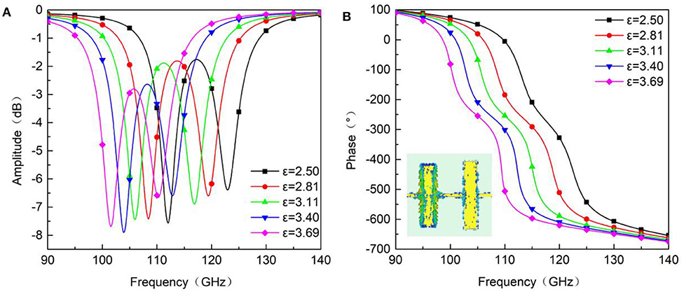
Figure 2. Simulated amplitude (A) and phase shift (B) as a function of frequency for different dielectric permittivities and surface current distribution around the double-dipole.
Wiring Scheme for Two-Dimensional Beam-Scanning
For simplification, most reported reconfigurable reflectarray phase-shifting units are connected by the same bias line in the same row [28]; however, this is insufficient for 2-D beam scanning. To achieve a better balance of fabrication complexity and 2-D beam scanning performance, a compromise with respect to wiring is introduced. For example, for a 39 × 39 reflectarray, every three patches in the same row are connected by a bias line parallel to the x-axis, and every three rows of the patches described above are surrounded by a rectangular loop bias line. The trunk bias lines pass through gaps between the adjacent unit cells along the x-axis, as shown in Figure 3. Thus, voltage can be applied individually to each 3 × 3 subarray. All bias lines and the distance between adjacent trunk bias lines are set to the same line width (10 μm). Because of the subarrays, the number of driving lines decreased significantly. The total number decreased from 1,521 to 169, which represents an 88.9% decrease.
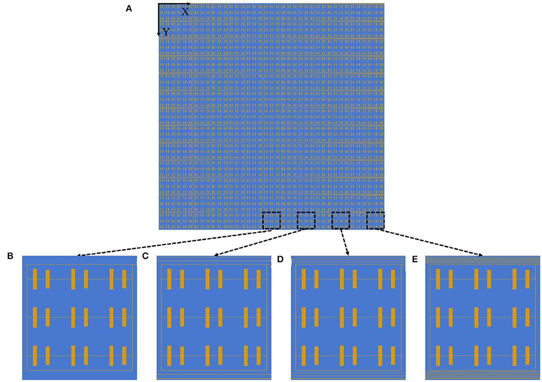
Figure 3. Wiring scheme of the whole antenna (A) and four driving line arrangements of a 3 × 3 subarray. None trunk bias line (B). Two trunk bias lines (C). Three trunk bias lines (D). Five trunk bias lines (E).
The effect of different driving line arrangements on the phase-shift performance is shown in Figure 4. Curve ‘a’ represents the phase shift vs. the relative permittivity for the phase-shifter elements with arrangement (B) in Figure 3. Curve ‘b’ represents the phase shift for arrangements (C), (D), and (E) in Figure 3. As shown, the average phase shift discrepancy between both cases is ~20° from 110 to 115 GHz, which remains within tolerance. The results show that the effect of different bias line arrangements on the phase shift performance was small and can thus be neglected. Under this wiring scheme, the phase and relative permittivity response curves of the phase-shift units still maintain high accuracy. This represents evidence for accurate phase compensation of the reconfigurable reflectarrays.

Figure 4. Comparisons of phase-shift performances for different bias line arrangements. Two trunk bias lines (A). Three trunk bias lines (B). Five trunk bias lines (C).
Design and Numerical Results of the Reflectarray
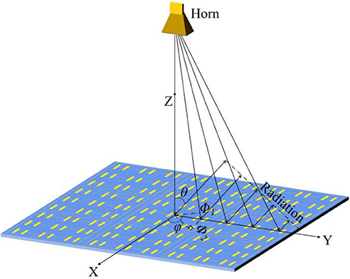
The reflectarray consists of 39 × 39 double-dipole phase shifter cells with a total area of 50.7 mm × 50.7 mm. Figure 5 shows a schematic of the planar reflectarray. A pyramid horn, located perpendicular to the reflectarray, is used as feeding horn. To ensure that the TM polarized wave of the 10-dB beam width emitted by the feed can cover the reflectarray, the distance between the phase center and the center of the reflectarray is set to 43.9 mm. The 10-dB beam width of the feed and the array aperture are 30° and 50.7 mm, respectively, are also considered.
The array is illuminated by the electromagnetic wave radiated from the primary feed, which generates the secondary radiation after phase compensation of the unit cells. According to the superposition principle of the vector field, the superposed wave can form a main beam with fixed direction in free space. The required phase compensation (Φx, y) consists of two parts; Φ1 compensates for the spatial phase delay caused by different distances from the feed to the array units, and Φ2 is the plane phase distribution that radiates electromagnetic waves toward the main beam direction (θ, ϕ). This can be expressed as follows:
Here, k0 = 2π/λ represents the free-space wave number (xi, yi), represents the coordinate for each array element, and (θi, ϕi) represents the direction from the phase center to each array element. With the bias voltage applied to each element, the unit cells obtain the corresponding phase distribution Φx, y. Figure 6 shows the phase distributions for scanning angles of−10°, 0°, 10°.
The far-field patterns of the reflectarray are calculated using finite integral technology (FIT) simulation. Figure 7 shows the simulated results for the elevation plane and azimuth plane for several angles at 115 GHz. For the elevation plane, the reflectarray performs a beam scanning range of 20°, with a maximum gain of 16.55 dBi at a scan angle of 0°, while the SLLs remains below −6.6 dB for the whole scanning range. The half-power beam-widths (HPBW) are 4.9, 5.6, and 5.8° at scanning angles of 0, −10, and 10°, respectively, which indicates good directivity.
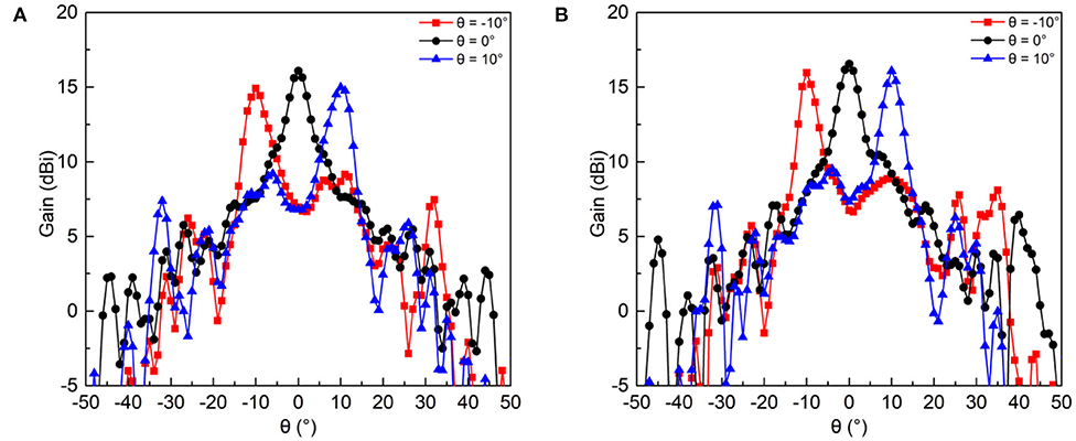
Figure 7. Simulated radiation patterns at 115 GHz for an azimuth angle ϕ of 90° (A) and an azimuth angle ϕ of 0° (B).
The antenna performance for the azimuth plane is slightly different because of the asymmetry of the structures of the unit cells. The beam-scanning range is 20°, as shown in Figure 7B. A maximum gain of 16.09 dBi is obtained for a scan angle of 0°, and the SLLs are below −6.1 dB with the HPBWs of 5.7° at scanning angle of 0°.
Table 2 shows the detailed electrical performance for the designed reflectarray for several scan angles. The performance of this antenna will improve when a 2 × 2 subarray and a more complicated driving circuit are used.
Conclusion
In this paper, a double-dipole phase shifter is designed with a phase range exceeding 360°. The wiring scheme for the 2-D beam-scanning attempted to balance structural simplification and performance. Based on a liquid-crystal phase shifter, an electrically controlled 2-D beam-scanning reflectarray for the F-band is presented. Simulation shows that the reflectarray reaches the maximum gain (16.55 dBi) for a scanning range of 20° and a very low SLL of −8.4 dB. Furthermore, the HPBW remains below 6.5° for several scanning angles. The new antenna may be used for terahertz imaging and detection.
Data Availability Statement
The datasets presented in this study can be found in online repositories. The names of the repository/repositories and accession number(s) can be found in the article/Supplementary Material.
Author Contributions
JY and PW planned and supervised the whole study, processed the raw data, and wrote and revised the manuscript. SS, YL, ZY, and GD advised on numerical calculation and analysis. All authors contributed to the article and approved the submitted version.
Funding
This work was supported by the National Natural Science Foundation of China (No. 61871171) and the Fundamental Research Funds for the Central Universities (No. JZ2018HGPB0276).
Conflict of Interest
The authors declare that the research was conducted in the absence of any commercial or financial relationships that could be construed as a potential conflict of interest.
Supplementary Material
The Supplementary Material for this article can be found online at: https://www.frontiersin.org/articles/10.3389/fphy.2020.576045/full#supplementary-material
References
1. Nagatsuma T, Ducournau G, Renaud CC. Advances in terahertz communications accelerated by photonics. Nat Photon. (2016) 10:371–9. doi: 10.1038/nphoton.2016.65
2. Shishanov S, Bystrov A, Hoare EG, Stove A, Gashinova M, Cherniakov M, et al. Height-finding for automotive THz radars. IEEE Trans Intell Transp Syst. (2019) 20:1170–80. doi: 10.1109/TITS.2018.2845542
3. Auton G, But DB, Zhang J, Hill E, Coquillat D, Consejo C, et al. Terahertz detection and imaging using graphene ballistic rectifiers. Nano Lett. (2017) 17:7015–20. doi: 10.1021/acs.nanolett.7b03625
4. Kawase K. Terahertz imaging for drug detection and large-scale integrated circuit inspection. Opt Photonics News. (2004) 15:34–9. doi: 10.1364/OPN.15.10.000034
5. Luo CG, Deng B, Wang HQ, Qin YL. High-resolution terahertz coded-aperture imaging for near-field three-dimensional target. Appl Optics. (2019) 58:3293–300. doi: 10.1364/AO.58.003293
6. Ji YY, Fan F, Chen M, Yang L, Chang SJ. Terahertz artificial birefringence and tunable phase shifter based on dielectric metasurface with compound lattice. Optics Express. (2017) 25:11405–13. doi: 10.1364/OE.25.011405
7. Manjappa M, Srivastava YK, Cong LQ, Al-Naib I, Singh R. Active photoswitching of sharp fano resonances in THz metadevices. Adv Mater. (2017) 29:6. doi: 10.1002/adma.201603355
8. Qiu KP, Jia N, Liu ZJ, Wu C, Fan YC, Fu QH, et al. Electrically reconfigurable split ring resonator covered by nematic liquid crystal droplet. Optics Express. (2016) 24:27096–103. doi: 10.1364/OE.24.027096
9. Fan YC, Shen NH, Zhang FL, Zhao Q, Wei ZY, Zhang P, et al. Photoexcited graphene metasurfaces: significantly enhanced and tunable magnetic resonances. ACS Photonics. (2018) 5:1612–8. doi: 10.1021/acsphotonics.8b00057
10. Fu XJ, Yang F, Liu CX, Wu XJ, Cui TJ. Terahertz beam steering technologies: from phased arrays to field-programmable metasurfaces. Adv Opt Mater. (2020) 8:22. doi: 10.1002/adom.201900628
11. Pozar DM, Targonski SD, Syrigos HD. Design of millimeter wave microstrip reflectarrays. IEEE Trans Antennas Propag. (1997) 45:287–96. doi: 10.1109/8.560348
12. Encinar JA. Design of two-layer printed reflectarrays using patches of variable size. IEEE Trans Antennas Propag. (2001) 49:1403–10. doi: 10.1109/8.954929
13. Niu TM, Withayachumnankul W, Ung BSY, Menekse H, Bhaskaran M, Sriram S, et al. Experimental demonstration of reflectarray antennas at terahertz frequencies. Optics Express. (2013) 21:2875–89. doi: 10.1364/OE.21.002875
14. Wan X, Qi MQ, Chen TY, Cui TJ. Field-programmable beam reconfiguring based on digitally-controlled coding metasurface. Sci Rep. (2016) 6:8. doi: 10.1038/srep20663
15. Babakhani B, Sharma SK, Labadie NR. A frequency agile microstrip patch phased array antenna with polarization reconfiguration. IEEE Trans Antennas Propag. (2016) 64:4316–27. doi: 10.1109/TAP.2016.2598156
16. Wang YM, Zhou GY, Zhang XS, Kwon K, Blanche PA, Triesault N, et al. 2D broadband beamsteering with large-scale MEMS optical phased array. Optica. (2019) 6:557–62. doi: 10.1364/OPTICA.6.000557
17. Dragoman M, Modreanu M, Povey IM, Iordanescu S, Aldrigo M, Romanitan C, et al. Very large phase shift of microwave signals in a 6nm HfxZr1-xO2 ferroelectric at +/- 3V. Nanotechnology. (2017) 28:5. doi: 10.1088/1361-6528/aa8425
18. Perez-Palomino G, Barba M, Encinar JA, Cahill R, Dickie R, Baine P, et al. Design and demonstration of an electronically scanned reflectarray antenna at 100 GHz using multiresonant cells based on liquid crystals. IEEE Trans Antennas Propag. (2015) 63:3722–7. doi: 10.1109/TAP.2015.2434421
19. Zheludev NI, Kivshar YS. From metamaterials to metadevices. Nat Mater. (2012) 11:917–24. doi: 10.1038/nmat3431
20. Hum SV, Perruisseau-Carrier J. Reconfigurable reflectarrays and array lenses for dynamic antenna beam control: a review. IEEE Trans Antennas Propag. (2014) 62:183–98. doi: 10.1109/TAP.2013.2287296
21. Li S, Wang J, Hao T, Li L, Liu J, Wang G, et al. Super terahertz phase shifter achieving high transmission and large modulation depth. Opt Lett. (2020) 45:2834–7. doi: 10.1364/OL.393571
22. Zografopoulos DC, Ferraro A, Beccherelli R. Liquid-crystal high-frequency microwave technology: materials and characterization. Adv Mater Technol. (2019) 4:22. doi: 10.1002/admt.201800447
23. Bildik S, Dieter S, Fritzsch C, Menzel W, Jakoby R. Reconfigurable folded reflectarray antenna based upon liquid crystal technology. IEEE Trans Antennas Propag. (2015) 63:122–32. doi: 10.1109/TAP.2014.2367491
24. Li JX, Jin T, Erni D, Meng FY, Wu Q, Li WN. Design and numerical demonstration of a 2D millimeter-wave beam-scanning reflectarray based on liquid crystals and a static driving technique. J Phys D Appl Phys. (2019) 52:9. doi: 10.1088/1361-6463/ab16bc
25. Yang J, Cai CG, Yin ZP, Xia TY, Jing SC, Lu HB, et al. Reflective liquid crystal terahertz phase shifter with tuning range of over 360 degrees. IET Microw Antennas Propag. (2018) 12:1466–9. doi: 10.1049/iet-map.2017.0898
26. Gao S, Yang J, Wang P, Zheng AD, Lu HB, Deng GS, et al. Tunable liquid crystal based phase shifter with a slot unit cell for reconfigurable reflectarrays in F-band. Appl Sci. (2018) 8:9. doi: 10.3390/app8122528
Keywords: terahertz, reconfigurable reflectarray, liquid crystal (LC), two-dimensional (2-D) beam scanning, millimeter and submillimeter wave antenna
Citation: Yang J, Wang P, Sun S, Li Y, Yin Z and Deng G (2020) A Novel Electronically Controlled Two-Dimensional Terahertz Beam-Scanning Reflectarray Antenna Based on Liquid Crystals. Front. Phys. 8:576045. doi: 10.3389/fphy.2020.576045
Received: 25 June 2020; Accepted: 01 September 2020;
Published: 06 October 2020.
Edited by:
Jinhui Shi, Harbin Engineering University, ChinaReviewed by:
Hui Feng Ma, Southeast University, ChinaYuancheng Fan, Northwestern Polytechnical University, China
Copyright © 2020 Yang, Wang, Sun, Li, Yin and Deng. This is an open-access article distributed under the terms of the Creative Commons Attribution License (CC BY). The use, distribution or reproduction in other forums is permitted, provided the original author(s) and the copyright owner(s) are credited and that the original publication in this journal is cited, in accordance with accepted academic practice. No use, distribution or reproduction is permitted which does not comply with these terms.
*Correspondence: Guangsheng Deng, ZGdzaEBoZnV0LmVkdS5jbg==
 Jun Yang
 Pengjun Wang
 Shuangyuan Sun2
 Guangsheng Deng
