- 1Center for Terahertz Waves and College of Precision Instrument and Optoelectronics Engineering, Tianjin University, and the Key Laboratory of Optoelectronics Information and Technology, Ministry of Education of China, Tianjin, China
- 2School of Electrical and Computer Engineering, Oklahoma State University, Stillwater, OK, United States
In recent years, metasurface-based focusing elements have gradually become an indispensable type of terahertz lenses. However, the meta-lens often suffers from chromatic aberration due to the intrinsic dispersion of each element, especially in the broadband application scenarios. In this paper, we design and demonstrate a silicon-based achromatic meta-lens working from 0.6 to 1.0 THz, which is polarization insensitive because of the adopted symmetrical structures. The simulated focal length and the full width at half maximum (FWHM) of the foci at different frequencies prove the achromatic behavior of our meta-lens compared with the chromatic counterpart. We also show that the focus shift incongruence of our design originates from the transmission amplitude distribution of the meta-lens. This article not only provides an achromatic planar lens working at terahertz domain but also reveals the importance of the amplitude distribution in the achromatic metasurface design.
1. Introduction
In recent years, the terahertz frequency domain has ushered in extensive and in-depth development. Various terahertz techniques and systems have been proposed for sensing, imaging, and communication scenarios, showing promising application prospects [1]. In almost all terahertz systems, the lens is an important component that can directly determine the performance of the system [2, 3]. Traditional terahertz lenses manipulate the output wavefront through phase accumulation along the propagation path via thickness variation, which is bound to a bulky size and curved shape, damaging the compactness of the lens. The metasurface, a 2D version metamaterial composed of an array of artificial subwavelength structures with the ability to engineer the phase, amplitude, and polarization features, has provided a new paradigm for the design of terahertz lenses. From the early metal gradient index terahertz lens to the all-dielectric meta-lens, which has attracted wide attention in recent years, metasurface-based focusing elements have gradually become an indispensable type of terahertz lenses. Compared with traditional terahertz lenses, terahertz meta-lenses composed of graphene [4, 5], silicon [6, 7], metals, etc. [8–14] can control the amplitude and/or phase distributions of the terahertz wavefront at quite a high freedom level to achieve novel focusing functions [15, 16]. Moreover, most meta-lenses have a planar shape and wavelength order thickness with potential outstanding integration capability.
However, compared with the silicon-based traditional terahertz lens, the meta-lens still faces the challenge of large chromatic aberration introduced by the mode dispersion of each meta-atom. For example, as the most mature terahertz technology, the time-domain spectroscopy uses a broadband terahertz pulse to analyze the spectrum of various materials, which has an natural demand for achromatic lenses. Recently in the visible domain, a huge line of meta-lens research has been dedicated to achieving the dispersion engineering. For instance, Khorasaninejad et al. [17] carried out a series of scientific researches on the achromatic meta-lens with a reflection mode. Chen et al. [18, 19] designed several achromatic meta-lenses with anisotropic nanostructures in the visible domain. Shrestha et al. [20] proposed an achromatic meta-lens working from 1,200 to 1,650 nm. Wang et al. [21, 22] demonstrated an achromatic meta-lens through integrated resonances for imaging. Despite those inspiring advances in the visible light domain, terahertz metasurfaces are critically different from visible light metasurfaces in terms of raw materials and structure design. Only sporadic study of achromatic meta-lenses has been conducted in the terahertz domain; Cheng et al. [23] proposed an achromatic lens based on silicon metasurface with a high aspect ratio. Though the achromatic behavior was demonstrated, the efficiency of their terahertz meta-lens is somehow limited, and the dispersion engineering capability is polarization sensitive due to the adopted geometrical phase modulation method.
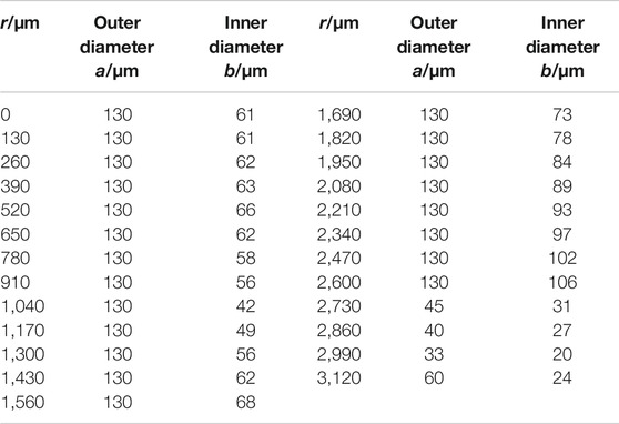
In this paper, we propose and investigate a silicon based meta-lens with a focal length of 11 mm and a diameter of 6.4 mm. Etched silicon pillars with 190 µm height are adopted as the unit cells to accumulate the required transmissive phase distribution. By changing the cross section of the pillars, alteration of the linear dispersion slop of each unit cell is achieved, which satisfies the requirement of an achromatic lens. The numerical investigation shows that our meta-lens has an achromatic bandwidth ranging from 0.6 to 1.0 THz that is polarization insensitive due to the
2. Design and Unit Cell Construction
The designed meta-lens is illustrated by Figure 1A. The desired phase distribution of a meta-lens working for a monochromatic wave can be expressed as
where ω is the wave frequency, c is the speed of light in vacuum, f is the focal length, and r and
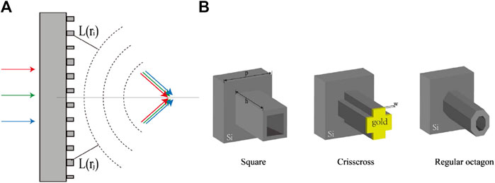
FIGURE 1. (A) The schematics of the achromatic meta-lens. The dashed lines represent the focusing wave front while the colored arrows represent the propagating directions of the terahertz waves at different frequencies. (B) The schematics of the adopted pillar structures with different cross section shapes; the height is 190 µm and the periodicity 130 µm. The yellow layer represents a gold layer of thickness 200 nm.
The unit cells for the achromatic meta-lens are thus expected to have a phase distribution
The first step in the construction of the unit cells is to select the right raw material by using the commercial software CST Microwave StudioTM and applying the periodic boundary condition with normal incidence wave. In the visible light domain, the substrate and the resonate cavity are often made of different materials in order to utilize the dispersion feature of the Mie scattering of a closed cavity. However, in the terahertz band, due to the ease of the fabrication and the consideration of absorption, dielectric metasurfaces prefer to etch structures directly onto the semi-insulating silicon substrates. As shown in Figure 2A, when both the substrate and the structure are made of silicon, a larger variation range of the phase and dispersion can be obtained by subwavelength pillar structure, compared to the fused silica structure with silicon substrate. Conversely, when the unit cell is made of a silicon pillar with fused silica substrate, its phase and dispersion have nearly the same ranges as the all silicon unit cells’, while the larger absorption and material dispersion of silica may cause problems in the design process.

FIGURE 2. (A) The phase-dispersion comparison of unit cells composed of different raw materials. (B,C) The amplitude and phase of the unit cells’ transmission for different cross section shapes, respectively.
Considering the aspect ratio in the dry etching process, we set the height of the silicon pillars as 190 µm, and the fabrication accessibility of our selection is supported by our previous work [25]. The periodicity of the unit cell was set as 130 µm, and our meta-lens has 49 unit cells in total with a diameter of 6.4 mm. A focal length of 13.5 mm and the target frequency ranging from 0.6 to 1.0 THz were determined as well for the followed unit cell construction process. Inspired by the previous work of Shrestha et al [20], we appropriately changed the cross-section geometry of the silicon pillars while retaining the

FIGURE 3. (A) The phase change ϕ of the structures as a function of size parameter a. The black line with squares and the red line with circles relate to the pure silicon structure and the corresponding meta-attached structure, respectively. (B) The phase-dispersion library of all the silicon pillars. Points in different colors in the figure represent different type of structures. (C) The phase-dispersion distributions of the achromatic meta-lens. The solid line is the ideal
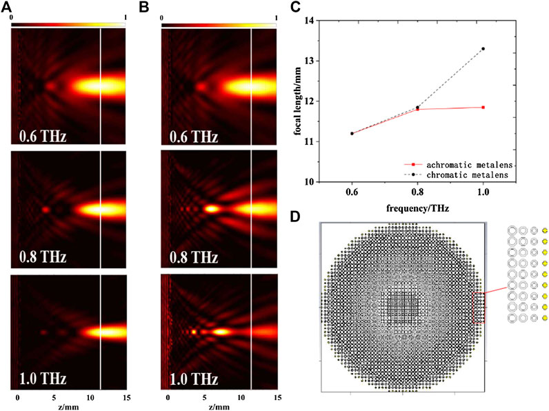
FIGURE 4. The simulated results of the focusing performance of the achromatic meta-lens and the chromatic counterpart. (A) The electric field intensity of the achromatic meta-lens in the
3. Numerical Demonstration and Analysis
The performance of our achromatic meta-lens was also evaluated using the CST Microwave Studio
Figure 5A depicts the intensity distributions of our achromatic meta-lens at the focal planes (
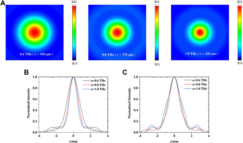
FIGURE 5. (A) The simulated focal spots of the achromatic meta-lens at 0.6, 0.8, and 1.0 THz of the achromatic meta-lens. (B) The horizontal cuts of the focal spots for achromatic meta-lens at 0.6 THz (black), 0.8 THz (red), and 1.0 THz (blue). (C) The horizontal cuts of the focal spots for the chromatic counterpart at 0.6 THz (black), 0.8 THz (red), and 1.0 THz (blue), respectively.
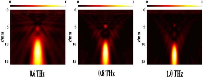
FIGURE 6. The simulated electric field intensity in the
4. Discussion
Although the simulation results have verified the feasibility of the designed achromatic meta-lens, the numerically obtained focal length is around 11.2 mm, which deviates 2.3 mm from the designed focal length of 13.5 mm. In addition, the focal lengths at 0.6 and 1.0 THz also differ by 650 µm. We believe this focal shift and the residual chromatic aberration are due to two reasons. The first one is the hexahedral mesh method in the simulation, which divides the space along Cartesian coordinates and will thus cause a calculation error because of the mismatch between the mesh grid and the tilted edge of the octagon pillars. The second reason is that focal shift is a prevalent phenomenon of the lens design [26], and we analyzed it from the perspective of the reversible light path. By assuming a point terahertz source located at
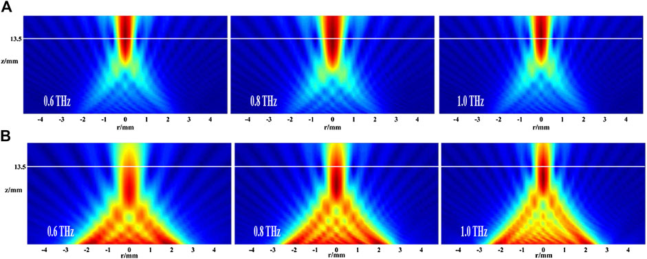
FIGURE 7. (A) The calculated ideal focusing performance of the achromatic meta-lens with the
5. Conclusion
In summary, we designed and numerically investigated an achromatic meta-lens composed of subwavelength silicon pillars working at terahertz frequencies. The achromatic behavior of the meta-lens was verified by the numerical simulation, which showed that its focal length changed by 650 µm when frequency ranged from 0.6 to 1.0 THz. The variation of the focal length is merely
Data Availability Statement
The original contributions presented in the study are included in the article/Supplementary Material, further inquiries can be directed to the corresponding authors.
Author Contributions
YG and JG discussed the design principle. YG and RJ completed the unit cell construction. YG performed the CST simulations, the matlab calculations, and the data analysis. YG wrote the paper, and JG modified the writing. All the authors commented on the paper.
Funding
National Natural Science Foundation of China (61307125, 61420106006, 61422509, 61575141, 61622505, 61975143); the US National Science Foundation (ECCS-1232081).
Conflict of Interest
The authors declare that the research was conducted in the absence of any commercial or financial relationships that could be construed as a potential conflict of interest.
Supplementary Material
The Supplementary Material for this article can be found online at: https://www.frontiersin.org/articles/10.3389/fphy.2020.606693/full#supplementary-material.
References
2. Cooper KB, Dengler RJ, Llombart N, Thomas B, Chattopadhyay G, Siegel PH. Thz imaging radar for standoff personnel screening. IEEE Transactions on Terahertz Science and Technology (2011) 1:169–82. doi:10.1109/TTHZ.2011.2159556
3. Trichopoulos GC, Mosbacker HL, Burdette D, Sertel K. A broadband focal plane array camera for real-time thz imaging applications. IEEE Trans Antenn Propag (2013) 61:1733–40. doi:10.1109/TAP.2013.2242829
4. Liu W, Hu B, Huang Z, Guan H, Li H, Wang X, et al. Graphene-enabled electrically controlled terahertz meta-lens. Photon Res (2018) 6:703–8. doi:10.1364/PRJ.6.000703
5. Huang Z, Hu B, Liu W, Liu J, Wang Y. Dynamical tuning of terahertz meta-lens assisted by graphene. JOSA B (2017) 34:1848–54. doi:10.1364/JOSAB.34.001848
6. Yu Q, Gu J, Yang Q, Zhang Y, Li Y, Tian Z, et al. All-dielectric meta-lens designed for photoconductive terahertz antennas. IEEE Photonics J (2017) 9:1–9. doi:10.1109/JPHOT.2017.2721503
7. Jia D, Tian Y, Ma W, Gong X, Yu J, Zhao G, et al. Transmissive terahertz metalens with full phase control based on a dielectric metasurface. Optic Lett (2017) 42:4494–7. doi:10.1364/OL.42.004494
8. Yang Q, Gu J, Wang D, Zhang X, Tian Z, Ouyang C, et al. Efficient flat metasurface lens for terahertz imaging. Optic Express (2014) 22:25931–9. doi:10.1364/OE.22.025931
9. Yang Q, Gu J, Xu Y, Zhang X, Li Y, Ouyang C, et al. Broadband and robust metalens with nonlinear phase profiles for efficient terahertz wave control. Advanced Optical Materials (2017) 5:1601084. doi:10.1002/adom.201601084
10. Luo J, Yu H, Song M, Zhang Z. Highly efficient wavefront manipulation in terahertz based on plasmonic gradient metasurfaces. Optic Lett (2014) 39:2229–31. doi:10.1364/OL.39.002229
11. Hu D, Moreno G, Wang X, He J, Chahadih A, Xie Z, et al. Dispersion characteristic of ultrathin terahertz planar lenses based on metasurface. Optic Commun (2014) 322:164–8. doi:10.1016/j.optcom.2014.02.017
12. Hu D, Wang X, Feng S, Ye J, Sun W, Kan Q, et al. Ultrathin terahertz planar elements. Adv Opt Mater (2013) 1:186–91. doi:10.1002/adom.201200044
13. Jiang XY, Ye JS, He JW, Wang XK, Hu D, Feng SF, et al. An ultrathin terahertz lens with axial long focal depth based on metasurfaces. Optic Express (2013) 21:30030–8. doi:10.1364/OE.21.030030
14. Wang S, Wang X, Kan Q, Ye J, Feng S, Sun W, et al. Spin-selected focusing and imaging based on metasurface lens. Optic Express (2015) 23:26434–41. doi:10.1364/OE.23.026434
15. Chang CC, Headland D, Abbott D, Withayachumnankul W, Chen HT. Demonstration of a highly efficient terahertz flat lens employing tri-layer metasurfaces. Opt Lett (2017) 42:1867–70. doi:10.1364/OL.42.001867
16. Jiang X, Chen H, Li Z, Yuan H, Cao L, Luo Z, et al. All-dielectric metalens for terahertz wave imaging. Optic Express (2018) 26:14132–42. doi:10.1364/OE.26.014132
17. Khorasaninejad M, Shi Z, Zhu AY, Chen WT, Sanjeev V, Zaidi A, et al. Achromatic metalens over 60 nm bandwidth in the visible and metalens with reverse chromatic dispersion. Nano Letters (2017) 17:1819–24. doi:10.1021/acs.nanolett.6b05137
18. Chen WT, Zhu AY, Sanjeev V, Khorasaninejad M, Shi Z, Lee E, et al. A broadband achromatic metalens for focusing and imaging in the visible. Nat Nanotechnol (2018) 13:220–6. doi:10.1038/s41565-017-0034-6
19. Chen WT, Zhu AY, Sisler J, Bharwani Z, Capasso F. A broadband achromatic polarization-insensitive metalens consisting of anisotropic nanostructures. Nat Commun (2019) 10:1–7. doi:10.1038/s41467-019-08305-y
20. Shrestha S, Overvig AC, Lu M, Stein A, Yu N. Broadband achromatic dielectric metalenses. Light Sci Appl (2018) 7:1–11. doi:10.1038/s41377-018-0078-x
21. Wang S, Wu PC, Su VC, Lai YC, Chu CH, Chen JW, et al. Broadband achromatic optical metasurface devices. Nat Commun (2017) 8:187. doi:10.1038/s41467-017-00166-7
22. Wang S, Wu PC, Su VC, Lai YC, Chen MK, Kuo HY, et al. A broadband achromatic metalens in the visible. Nat Nanotechnol (2018) 13:227–32. doi:10.1038/s41565-017-0052-4
23. Cheng Q, Ma M, Yu D, Shen Z, Xie J, Wang J, et al. Broadband achromatic metalens in terahertz regime. Sci Bull (2019) 64:1525–31. doi:10.1016/j.scib.2019.08.004
24. Aieta F, Kats M, Genevet P, Capasso F. Applied optics. Multiwavelength achromatic metasurfaces by dispersive phase compensation. Science (2015) 347:1342–5. doi:10.1126/science.aaa2494
25. Xu Y, Li Q, Zhang X, Wei M, Xu Q, Wang Q, et al. Spin-decoupled multifunctional metasurface for asymmetric polarization generation. ACS Photonics (2019) 6:2933–41. doi:10.1021/acsphotonics.9b01047
26. Li Y, Wolf E. Focal shift in focused truncated Gaussian beams. Optic Commun (1982) 42:151–6. doi:10.1016/0030-4018(82)90128-6
Keywords: achromatic, meta-lens, polarization independent, terahertz, metasurfaces
Citation: Gao Y, Gu J, Jia R, Tian Z, Ouyang C, Han J and Zhang W (2020) Polarization Independent Achromatic Meta-Lens Designed for the Terahertz Domain. Front. Phys. 8:606693. doi: 10.3389/fphy.2020.606693
Received: 15 September 2020; Accepted: 16 November 2020;
Published: 21 December 2020.
Edited by:
Longqing Cong, University of Pennsylvania, United StatesReviewed by:
Lin Chen, University of Shanghai for Science and Technology, ChinaM. Ren, Nankai University, China
Copyright © 2020 Gao, Gu, Jia, Tian, Ouyang, Han and Zhang. This is an open-access article distributed under the terms of the Creative Commons Attribution License (CC BY). The use, distribution or reproduction in other forums is permitted, provided the original author(s) and the copyright owner(s) are credited and that the original publication in this journal is cited, in accordance with accepted academic practice. No use, distribution or reproduction is permitted which does not comply with these terms.
*Correspondence: Jianqiang Gu, Z2pxQHRqdS5lZHUuY24=; Weili Zhang, d2VpbGkuemhhbmdAb2tzdGF0ZS5lZHU=
 Yufei Gao1
 Jianqiang Gu
 Weili Zhang