Abstract
In this paper, a reconfigurable circular-ring feed patch antenna for polarization diversity applications is proposed. The reconfigurability is realized by using only two p-i-n diodes which are inserted into the circular feed ring of the aperture-coupled patch antenna. With the help of the p-i-n diodes, the polarization of the antenna is able to be altered among 45° linearly polarized (LP), left-hand circularly polarized (LHCP), and right-hand circularly polarized (RHCP) states. A fully-functional prototype is fabricated and measured. The measurement agrees well with the simulation and three polarization states are obtained. Owing to the merits of tri-polarization diversity, low profile and simple structure, the proposed design is a great candidate for future wireless systems.
Introduction
With the popularity of wireless communication technologies, reconfigurable antennas with switchable linearly polarized (LP) or circularly polarized (CP) waves have been receiving much attention. They can enhance the performance of radio-frequency systems due to their advantages of reducing polarization mismatch and mitigating multi-path fading effects [1–3]. In the past few years, many works have been undertaken on the design of polarization reconfigurable antennas [4–12]. In [4–7], the designs can provide LP reconfiguration along different polarization directions. CP reconfigurable antennas, with the ability of switching the polarization between left-hand circularly polarized (LHCP) and right-hand circularly polarized (RHCP) states, have been reported in [8–10]. It is observed that these designs can only alter the polarization either between LP modes or between CP modes. In particular, a reconfigurable antenna which can switch its polarization between LP state and CP state is preferred. To realize it, the designs in [11, 12] achieved a pair of orthogonal CP waves and an LP wave in a single antenna structure.
Due to the feature of simple structure and easy fabrication, the resonant-type series feeding cross-aperture coupled microstrip antenna have been studied over the past decades. This type of antenna is flexible to realize CP operation with wide axial ratio bandwidth and flat gain bandwidth. Its detailed radiating mechanism has been systematically analyzed based on the theory of the transmission line model [13] and the reciprocity method [14]. Based on this idea, it is possible to design dual-band CP radiation. In [15], the authors employed a series feed line to couple a diamond-shaped slot to a ring and a cross-slot to a patch in series in order to realize a dual-band CP antenna. To minimize its size, several modifications, including the cross-shaped slots replaced by multiple slots and the series feeding line replaced by an open-ended circular ring, were made to obtain a more compact one as explored in [16]. Therefore, the series feeding aperture-coupled microstrip antenna becomes attractive for polarization reconfigurable designs.
In this paper, a polarization reconfigurable circular-ring fed patch antenna is proposed. Two p-i-n diodes are soldered on the circular feed ring. By controlling the states of the p-i-n diodes, the antenna polarization can be switched between a pair of orthogonal CP modes and an LP mode. In addition, two 68-pF capacitors are used to block DC signals. Compared with the designs presented in [13–16], the proposed antenna can also provide an additional LP state. Compared with tri-polarization diversity antennas demonstrated in [11, 12], the proposed design has a much lower profile. Details of the simulated and measured results are presented to validate the proposed design.
Antenna Design
Antenna Geometry
The three-dimensional configuration of the proposed antenna is illustrated in Figure 1, which consists of two microwave FR4 substrates (Substrate 1 and 2) and an air layer. Both the FR4 substrates are with the same thickness of 0.8 mm, radius of 48 mm and relative permittivity of 4.4, and they are separated by an air-gapped layer with a height of Ha. The side and top views are presented in Figure 2, and the detailed dimensions of the proposed antenna are given in Table 1. For the radiator, there are four square patches printed on the top surface of Substrate 1 with 90° rotation between each other. On the top surface of the lower FR4 substrate, there is a switchable circular-ring microstrip line, and the bottom is a ground plane with four identical slots right below the four patches. As such, the proposed antenna can be excited by an aperture-coupling scheme. It should be noted that a conventional aperture-coupled structure is realized by placing a microstrip feedline above the coupling slots. But in this design, the configuration is right reversed. The purpose of this arrangement is for the purpose of directly feeding the antenna with a coaxial probe in the center.
FIGURE 1
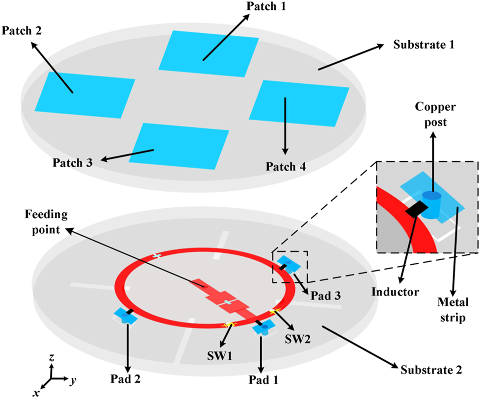
Three-dimensional configuration of the proposed polarization reconfigurable antenna.
FIGURE 2
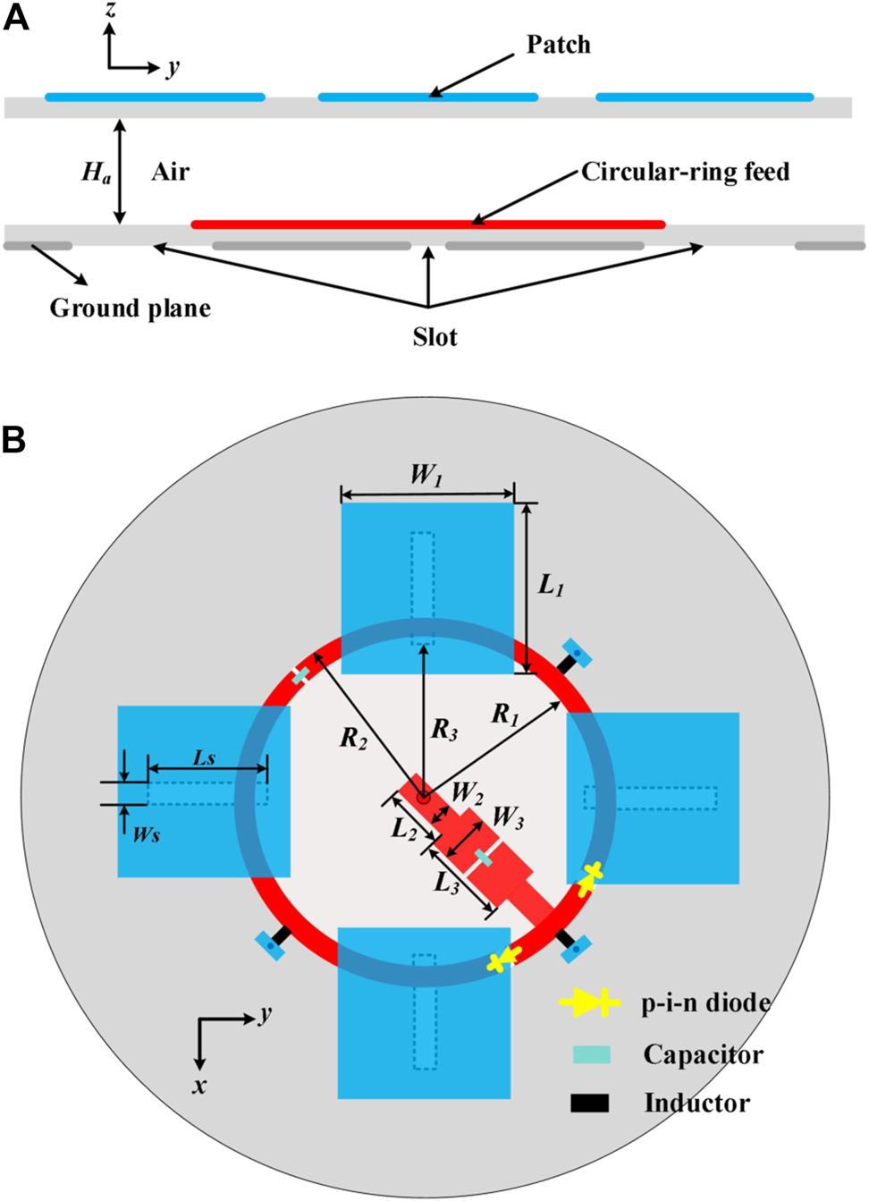
Side and top views of the proposed polarization reconfigurable antenna: (A) Side view; (B) Top view.
TABLE 1
| Parameters | Ha | L1 | L2 | L3 | W1 |
|---|---|---|---|---|---|
| Values/mm | 2 | 23 | 6.8 | 14 | 23 |
| Parameters | W2 | W3 | Ls | Ws | R1 |
| Values/mm | 2 | 3.6 | 20.5 | 2 | 19.7 |
| Parameters | R2 | R3 | — | — | — |
| Values/mm | 21.7 | 19.5 | — | — | — |
Dimensions of the proposed antenna.
Operating Principle
In the proposed design, two p-i-n diodes, named SW1 and SW2, are inserted into the circular-ring microstrip line, constituting a direction-switchable line. The p-i-n diodes used here as switches, are MADP-000907-14020P from MACOM [17]. The diode is ON when it is forward biased by using a 1.5-V DC voltage. If the diode is unbiased, it will be turned OFF. To control the states of the diodes, three groups of DC pads are used in the design, labeled as Pad 1, Pad 2, and Pad 3. Three slots are etched on the ground plane to ensure the independent control of the DC pads. Besides, two 68-pF capacitors are used to block DC signals and three 47-nH inductors are utilized to isolate DC lines from RF signals. It needs to be mentioned that the biasing circuit is located below the ground plane with the help of metal strips and copper posts, so the effect of the biasing circuit on the antenna performances is limited.
As illustrated above, the design can switch the polarization among two orthogonal CP states and an LP state. The details are depicted in Table 2. When SW1 is ON and SW2 is OFF, four slots etched on the ground plane are excited with a sequential phase in clockwise direction. Because slots are used as the source to feed the patches, RHCP wave is realized. Similarly, when SW1 is OFF and SW2 is ON, four slots etched on the ground plane are excited with a sequential phase in anticlockwise direction. Hence, LHCP wave is obtained. Finally, the LP state is achieved when both SW1 and SW2 are ON.
TABLE 2
| State | SW1 | SW2 |
|---|---|---|
| RHCP | ON | OFF |
| LHCP | OFF | ON |
| LP | ON | ON |
Different polarization states.
Figure 3 gives the simulated current distribution on the patches over a period when SW1 is ON and SW2 is OFF. At time t = 0 and T/2 (T is a period of time), the current is along x-direction on Patch 1 and Patch 3 and current on the other two patches is minimized. At time t = T/4 and 3T/4, the y-direction current is dominant on Patch 2 and Patch 4 and the current on Patch 1 and Patch 3 is weak. Therefore, CP radiation is realized when SW1 is ON and SW2 is OFF. According to the rotated direction of the current, it is demonstrated that the antenna works under the RHCP state. In terms of LP state, the simulated current distribution on the patches over a period when both SW1 and SW2 are ON is presented in Figure 4. As the figure illustrates, at time T = 0, current on Patch 2 and Patch 4 flows along the x direction, and current on Patch 1 and Patch 3 flows along the y direction. Thus, the resultant current is along the direction of φ = 45°. When t = T/2, the resultant current is opposite to that of t = 0. As a result, 45° LP radiation is achieved.
FIGURE 3
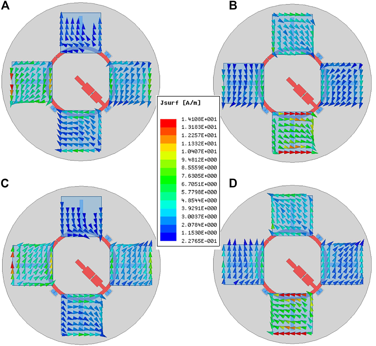
Simulated current distribution on the patches over a period of time when SW1 is ON and SW2 is OFF: (A)t = 0; (B)t = T/4; (C)t = T/2; (D)t = 3T/4.
FIGURE 4
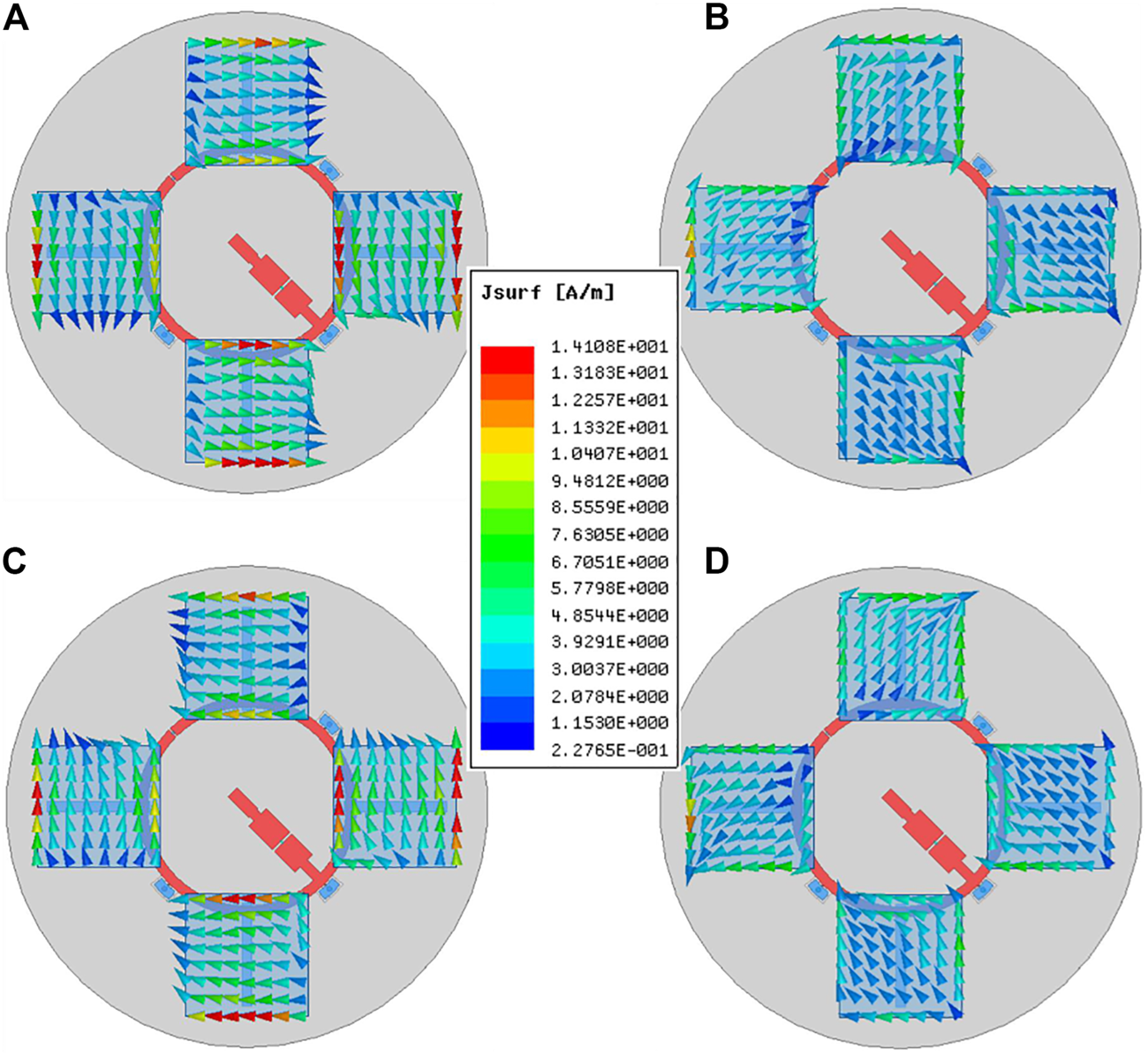
Simulated current distributions on the patches over a period of time when both SW1 and SW2 are ON: (A)t = 0; (B)t = T/4; (C)t = T/2; (D)t = 3T/4.
Simulated and Measured Results
For experimental validation, a fully-functional prototype was fabricated and measured. Figure 5 dsplays the photograph of the constructed prototype. As seen from the photograph, the two PCB layers are connected with each other using some plastic supports. The Ansys HFSS is used in the simulation [18]. The measured results, including S-parameters, the gain values and radiation patterns were obtained with a Keysight E5080A network analyzer and a near-field antenna measurement system, respectively.
FIGURE 5
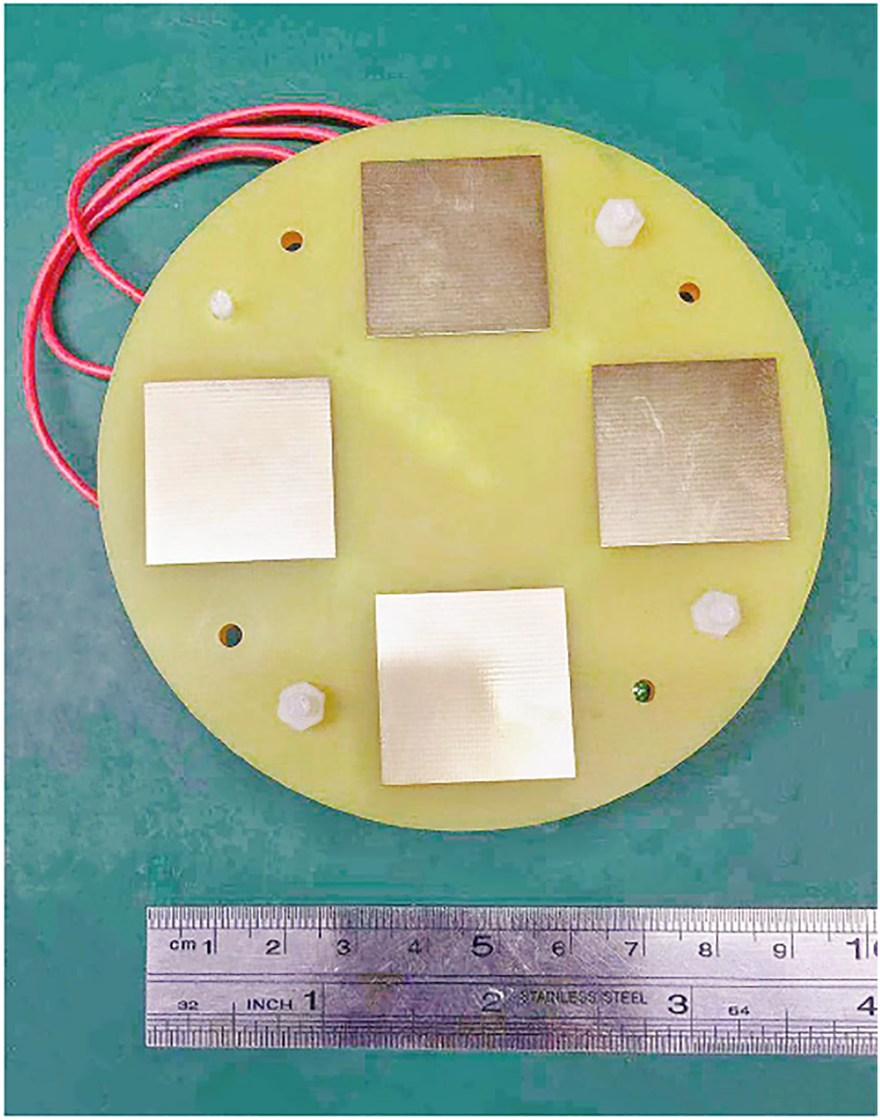
Photograph of the proposed antenna.
The simulated and measured reflection coefficients of the proposed antenna under different states are given in Figure 6. As Figure 6 shows, the measured −10 dB impedance bandwidth is almost the same for two CP states: 9.7% from 3.32 to 3.66 GHz. The measured -10 dB impedance bandwidth for LP state is 9.7% from 3.34 to 3.68 GHz. Figure 7 depicts the simulated and measured axial ratios (ARs) for two CP states. The measured AR bandwidth is from 3.44 to 3.64 GHz for LHCP state and from 3.42 to 3.6 GHz for RHCP state. The discrepancy between the simulations and the measurements is mainly due to the fabrication tolerance and the imperfect environment of the measured system. Therefore, the measured effective operation band for both S11 ≤ −10 dB and AR ≤ 3 dB is from 3.43 to 3.6 GHz.
FIGURE 6
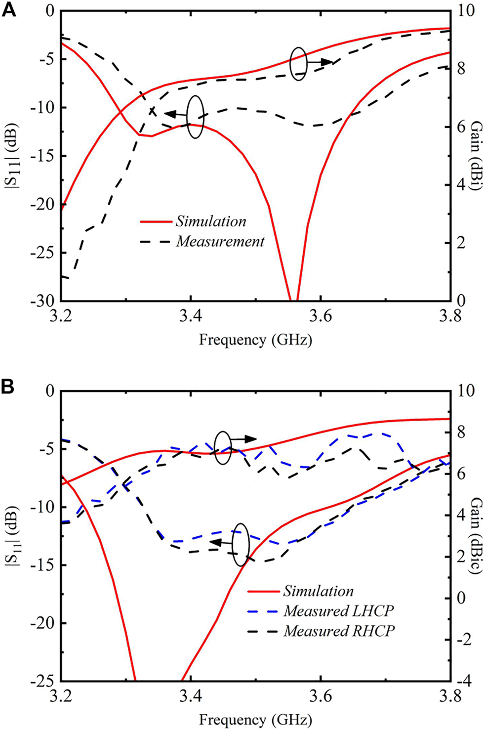
Simulated and measured reflection coefficients and broadside gains of the proposed antenna: (A) LP state; (B) CP states.
FIGURE 7

Simulated and measured ARs of the proposed antenna for two CP states.
The simulated and measured broadside gains of the proposed antenna in three states are also depicted in Figure 6. Within the effective bandwidth, for two orthogonal CP states, the measured gain is around 7 dBic; for the LP state, the measured gain is from 7.5 to 8.7 dBi. The measured efficiencies over the effective band is more than 75% for all three polarization states.
Figure 8 gives the simulated and measured radiation patterns in LHCP and LP states at 3.5 GHz. Patterns in RHCP states are not given for brevity. From the results, it is seen that unidirectional radiation patterns are obtained. As shown in Figure 8 (a), the measured co-polarized fields at θ = 90° are approximately 22 dB stronger than the corresponding cross-polarized counterpart. Hence, CP radiation is realized. As for LP state, the measured cross-polarization levels are as low as no more than −18 dB in both planes. The measured radiation patterns agree well with the simulations in the broadside direction. The differences between simulated and measured radiation patterns in the back side are mainly owing to the influence of DC cables.
FIGURE 8
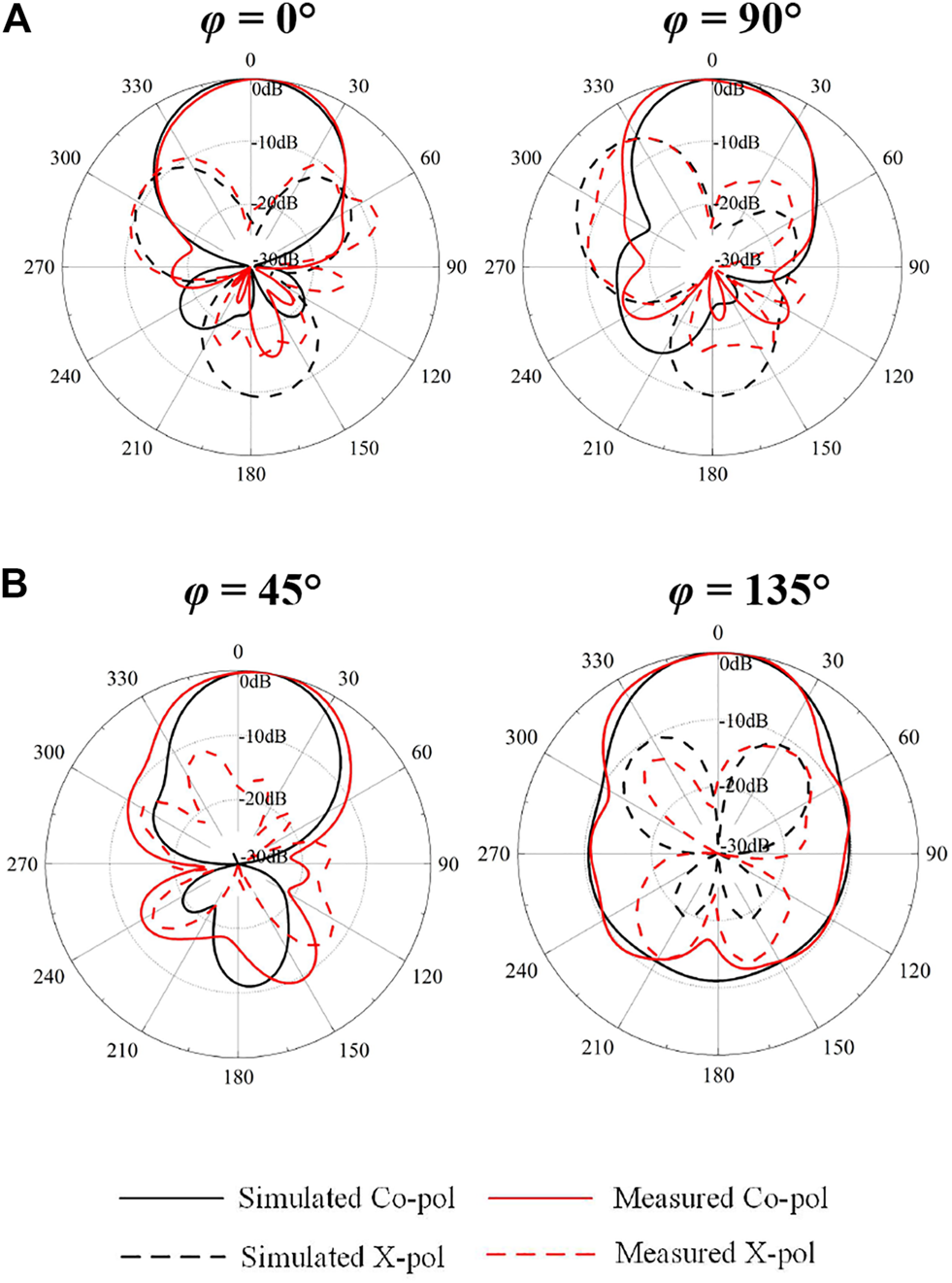
Simulated and measured radiation patterns: (A) 3.5 GHz in LHCP state; (B) 3.5 GHz in LP state.
Table 3 lists a comparison between our work and other reported polarization reconfigurable antennas. Compared with the reported designs, the proposed antenna has a much lower profile with three different polarization states.
Conclusion
A reconfigurable circular-ring feed patch antenna has been presented. Three polarization states are achieved by controlling the states of two diodes. A prototype was designed, fabricated and measured to verity the design idea. An overlapped bandwidth of 4.8% is achieved and radiation patterns are stable within the operating band. Due to merits of tri-polarization diversity, low profile and simple structure, the proposed antenna is promising for future wireless systems.
Statements
Data availability statement
The original contributions presented in the study are included in the article/Supplementary Material, further inquiries can be directed to the corresponding author.
Author contributions
All authors listed have made a substantial, direct, and intellectual contribution to the work and approved it for publication.
Conflict of interest
The authors declare that the research was conducted in the absence of any commercial or financial relationships that could be construed as a potential conflict of interest.
Publisher’s note
All claims expressed in this article are solely those of the authors and do not necessarily represent those of their affiliated organizations, or those of the publisher, the editors and the reviewers. Any product that may be evaluated in this article, or claim that may be made by its manufacturer, is not guaranteed or endorsed by the publisher.
References
1.
RowJ-SHouM-J. Design of Polarization Diversity Patch Antenna Based on a Compact Reconfigurable Feeding Network. IEEE Trans Antennas Propagat (2014) 62(10):5349–52. 10.1109/tap.2014.2341271
2.
GuoYXBianLShiXQ. Broadband Circularly Polarized Annular-Ring Microstrip Antenna. IEEE Trans Antennas Propagat (2009) 57(8):2474–7. 10.1109/tap.2009.2024584
3.
PanYMZhengSYHuBJ. Wideband and Low-Profile Omnidirectional Circularly Polarized Patch Antenna. IEEE Trans Antennas Propagat (2014) 62(8):4347–51. 10.1109/tap.2014.2323412
4.
WuFLukK-M. A Reconfigurable Magneto-Electric Dipole Antenna Using Bent Cross-Dipole Feed for Polarization Diversity. Antennas Wirel Propag Lett (2017) 16:412–5. 10.1109/lawp.2016.2581259
5.
GuHWangJGeLSimC-Y -D. A New Quadri-Polarization Reconfigurable Circular Patch Antenna. IEEE Access (2016) 4:4646–51. 10.1109/access.2016.2600250
6.
WongHLinWHuitemaLArnaudE. Multi-polarization Reconfigurable Antenna for Wireless Biomedical System. IEEE Trans Biomed Circuits Syst (2017) 11(3):652–60. 10.1109/tbcas.2016.2636872
7.
LinWWongH. Polarization Reconfigurable Aperture-Fed Patch Antenna and Array. IEEE Access (2016) 4:1510–7. 10.1109/access.2016.2552488
8.
ZhangLGaoSLuoQYoungPRLiQ. Wideband Loop Antenna with Electronically Switchable Circular Polarization. Antennas Wirel Propag Lett (2017) 16:242–5. 10.1109/lawp.2016.2570859
9.
KhidreALeeK-FYangFElsherbeniAZ. Circular Polarization Reconfigurable Wideband E-Shaped Patch Antenna for Wireless Applications. IEEE Trans Antennas Propagat (2013) 61(2):960–4. 10.1109/tap.2012.2223436
10.
LinWWongH. Wideband Circular-Polarization Reconfigurable Antenna with L-Shaped Feeding Probes. Antennas Wirel Propag Lett (2017) 16:2114–7. 10.1109/lawp.2017.2699289
11.
WangKXWongH. A Reconfigurable CP/LP Antenna with Cross-Probe Feed. Antennas Wirel Propag Lett (2017) 16:669–72. 10.1109/lawp.2016.2598248
12.
GeLYangXZhangDLiMWongH. Polarization-Reconfigurable Magnetoelectric Dipole Antenna for 5G Wi-Fi. Antennas Wirel Propag Lett (2017) 16:1504–7. 10.1109/lawp.2016.2647228
13.
AloniEKastnerR. Analysis of a Dual Circularly Polarized Microstrip Antenna Fed by Crossed Slots. IEEE Trans Antennas Propagat (1994) 42:1053–8. 10.1109/8.309996
14.
KimHLeeBMYoonY-J. A Single-Feeding Circularly Polarized Microstrip Antenna with the Effect of Hybrid Feeding. Antennas Wirel Propag Lett (2003) 2:74–7. 10.1109/lawp.2003.813382
15.
ChangT-NLinJ-M. Serial Aperture-Coupled Dual Band Circularly Polarized Antenna. IEEE Trans Antennas Propagat (2011) 59(6):2419–23. 10.1109/tap.2011.2144553
16.
ChangTNLinJM. A Novel Circularly Polarized Patch Antenna with a Serial Multislot Type of Loading. IEEE Trans Antennas Propagat (2007) 55(11):3345–8. 10.1109/tap.2007.908846
17.
MACOM. MADP-000907-14020P PIN Diode (2015). Available: http://www.macom.com/products/product-detail/MADP- 000907-14020P.
18.
Ansys Corp. HFSS: High Frequency Structure Simulator Based on the Finite Element Method (2021). Available: http://www.ansys.com.
Summary
Keywords
antenna, patch antenna, reconfigurable antenna, polarization reconfiguration, switch
Citation
Gu H, Ge L and Zhang J (2021) Reconfigurable Circular-Ring Feed Patch Antenna with Tri-Polarization Diversity. Front. Phys. 9:752505. doi: 10.3389/fphy.2021.752505
Received
03 August 2021
Accepted
01 September 2021
Published
13 September 2021
Volume
9 - 2021
Edited by
Lei Guo, The University of Queensland, Australia
Reviewed by
MEI LI, Chongqing University, China
Mohd Fairus Mohd Yusoff, University Technology Malaysia, Malaysia
Juhua Liu, Sun Yat-sen University, China
Updates
Copyright
© 2021 Gu, Ge and Zhang.
This is an open-access article distributed under the terms of the Creative Commons Attribution License (CC BY). The use, distribution or reproduction in other forums is permitted, provided the original author(s) and the copyright owner(s) are credited and that the original publication in this journal is cited, in accordance with accepted academic practice. No use, distribution or reproduction is permitted which does not comply with these terms.
*Correspondence: Lei Ge, leige@szu.edu.cn
This article was submitted to Radiation Detectors and Imaging, a section of the journal Frontiers in Physics
Disclaimer
All claims expressed in this article are solely those of the authors and do not necessarily represent those of their affiliated organizations, or those of the publisher, the editors and the reviewers. Any product that may be evaluated in this article or claim that may be made by its manufacturer is not guaranteed or endorsed by the publisher.