 Fabio Callegari1,2
 Aymeric Le Gratiet1,3
 Alessandro Zunino1,2
 Ali Mohebi1,2
 Paolo Bianchini1
 Alberto Diaspro1,2*
- 1Nanoscopy and NIC@IIT, Istituto Italiano di Tecnologia (IIT), Genoa, Italy
- 2Department of Physics, University of Genoa, Genoa, Italy
- 3Université de Rennes, CNRS, Institut FOTON - UMR 6082, Lannion, France
Mueller Matrix Microscopy exploits the generation and the analysis of polarized light to create label-free contrast in biological images. However, when dealing with Optical Scanning Microscopy, it is required a fast generation of the polarization states in order to obtain a good Signal-to-Noise Ratio at the pixel-dwell time rate. In this work, we propose a microscopy system based on a scanning beam architecture that is exploiting the simultaneous emission of orthogonal polarization states from a Zeeman laser to provide Mueller Matrix images. This approach is based on the detection of an interference signal that allows to time-encode polarization states directly from the laser source, without the need for further active components for the management of the polarization states. We provide the theoretical model behind this approach and we apply our new method to the imaging of biological samples. Our Mueller Matrix imaging setup enables high-speed scanning microscopy, while preserving compactness and simplicity of construction. Our findings may lead to more effective dissemination of label-free techniques and their use by biological researchers.
1 Introduction
Optical microscopy techniques are among the most widely used imaging approaches in biological research. The most widely adopted microscopy methods are based on the detection of the fluorescence signal from a labelled sample. In most cases, this requires a precise preparation protocol in which fluorescent labels are properly linked to the specific structure of interest inside the specimens. However, there is an increasing interest also in label-free approaches, providing imaging contrast to biological structures without the need for any staining. Polarized light can be effectively exploited for this task. Indeed, the polarization state of the light can be altered by sample anisotropies, enabling label-free contrast, sensitive to morphological properties of the objects [1–3]. Different structural conformations, sizes, and orientations of inner structures inside specimens respond differently to polarized light, providing fingerprint signals without the need for fluorophores. Thus, complex sample preparation protocols are typically not needed. Furthermore, the light dose required to detect a polarization response is orders of magnitude lower than that required by fluorescence-based or nonlinear imaging methods. Therefore, polarization-based imaging techniques are a class of extremely gentle techniques with a very small risk of photodamage. The absence of the labelling molecules is an advantage when long observation times are needed since the photo-bleaching as well as most of the other issues related to the high light dose are inherently avoided.
Mueller Matrix (MM) imaging is becoming an increasing trend in label-free microscopy applied to biological investigations [4]. This approach relies on the Stokes-Mueller formalism [5, 6] describing the polarized light with a
The MM measurement is straightforward: a beam of light described by known Stokes vector (
Here, the capability to encode the polarization information, i.e., to generate different
2 Materials and Methods
2.1 Laser Source and PSG
The first realization of a Zeeman Laser is close to the invention of the He-Ne gas laser [16, 17]: its peculiar light emission can be described as a dual-frequency, dual-polarization (DFDP) output and the build-up of this complex electromagnetic radiation is due to the well-known Zeeman Effect [11]. As anticipated, in our method this device acts both as light source and as PSG thanks to this peculiar laser emission. This laser system has been realized by using a custom 3D-printed mechanical holder to hold a commercial He-Ne laser tube (Uniphase, United States) and seven arrays of rare-earth magnets. Placed in a radial configuration around the laser tube, they trigger the Zeeman effect in the gain medium: thus, the output consists of a stable 1 mW red beam at 633 nm, made up of two laser lines spaced by 700 kHz. This configuration enables the beams to have orthogonal circular polarization states, typical of the Longitudinal Zeeman Effect Laser. Since the stability of the frequency spacing of these two optical components is also linked to the resonator length, a custom Stabilization Unit (SU) has been assembled to make the laser working properly. A beating signal (
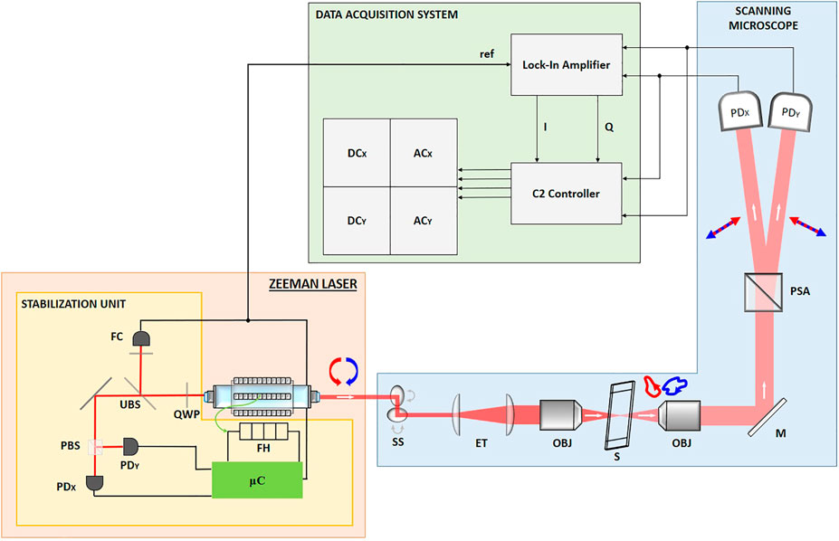
FIGURE 1. Scheme of the microscopy setup shined by the ZL. The white arrows represent the direction of the beam, whereas the red and blue arrows are describing the polarization states. The main output of the ZL travels through a Scanning Stage (SS), an Expanding Telescope (ET), excitation and detection objectives (obj) in between which the sample (S) is placed. Finally, the polarization is split by the Wollaston Prism (acting as PSA) and detected by means of two fast photodiodes (PDX and PDY).
2.2 Architecture of the Microscope
The architecture of the scanning microscopy system can be seen in the blue box in Figure 1. A Scanning Stage (C2+, Nikon Instruments, JA) performs the raster scanning of the laser beam. A 20X/0.5NA Nikon objective (DIC-M Plan Fluor, Nikon Instruments, JA) has been used to focus the light on the sample and after this interaction, the transmitted light is collected by a 4X/0.13NA Nikon objective (CFI Plan Fluor, Nikon Instruments, JA).
The polarization state is analyzed employing a Wollaston Prism (WP10, Thorlabs, United States) – acting as PSA – aligned to separate the X-polarized and the Y-polarized components. These two output beams carry the interference signal of the ZL detected with a couple of Si-Amplified photodiodes (PDX and PDY, PDA36A-EC, Thorlabs, United States). The photocurrents signals are split into two parts and then conditioned, digitalized and stored by the units in the green box of the scheme: first, their AC components are extracted with a Lock-In Amplifier (LA, HF2LI, Zurich Instruments, CH) by means of an In-Phase/Quadrature (I/Q) demodulation. In order to do so, a phase reference is required and it is provided by feeding the LA with a reference beating signal coming from the SU of the Zeeman Laser. Meanwhile, the DC components are directly obtained by the Nikon C2 Workstation that is receiving also the LA output after the I/Q demodulation. Then, a Dell Workstation, where the Nikon NIS-elements software is installed, has been used to perform the real-time check on the imaging results of the setup. The analysis of the experimental data has been carried out employing custom Matlab (Mathworks, United States) routines.
2.3 Measurements of the Mueller Coefficients by Means of the Zeeman Beating Line
The following simple description of the electromagnetic field associated with the output of a Zeeman Laser is useful to appreciate its DFDP content:
where
However, the intensity-based description of the polarization states carried out by the Stokes vector is more useful when dealing with Mueller Matrix Microscopy, as stated by McClain et al. [18].
Notably, two elements are oscillating at the beating frequency (
Where the effect of the PSA is described by
The first element of each output Stoke vector in Eqs 5, 6 represents the intensity detected by the two photodiodes after the PSA: it contains information about Mueller coefficients of the sample matrix that are associated both to its DC and AC component, as shown by the following equations.
Where
With this configuration, the following six elements of the Mueller Matrix of the sample can be identified at the rate of the Zeeman Beating Frequency. The DC amplitudes are given by the average of the oscillating signal, whereas the AC components are the results of the I/Q demodulation carried out by the Lock-In Amplifier with the reference signal, oscillating at the beating frequency too. The measured MM coefficients are the following
The measured values are used to build pixel-by-pixel the corresponding six images.
2.4 Sample Preparation
The validation of the polarization measurement has been carried out with some reference polarization optics, namely a Linear Polarizer (VIS 700 BC4 CW02 ColorPol, CODIXX AG, DE) and a Half-Wave Plate (AHWP10M-600, Thorlabs, United States): the coefficients of their Mueller Matrices have been measured and then compared with reference theoretical values. The imaging capabilities were tested on biological samples. Dried thin slices of potatoes were put in a microscopy glass slide: the starch granules embedded in them have been imaged because of their strong response to polarized light. The other sample is made of collagen fibres from the medial collateral ligament of rat knee (female Sprague–Dawley rats, 3 months old). After removal of the fascia and overlying muscles, the ligament was drop-fixed with the appropriate fixative, 10% neutral buffered formalin for 24 h, dehydrated in graded alcohols, embedded in paraffin and sectioned at a thickness of 7 μm [19].
3 Applications
3.1 Characterization of Polarization Setup Performances
The validation of the technique has been carried out by calibrating the setup to reproduce the ideal response of the air and then by characterizing Polarization Optics exhibiting a strong dichroic and birefringent response. Without any sample in the objective focal plane, the polarization response of the air is that of the identity matrix. So elements lying in the main diagonal of the Mueller Matrix of the air should have a value close to 1 whereas the off-diagonal elements must be nearly 0. This calibration is taking into account the different responses of the two photodiodes in the detection stage after the PSA and other non-idealities in the experimental setup. Then, the pixels associated with the image of each Mueller coefficient has been normalized with the m00 image, representing the total intensity of the light transmitted by the sample. The results of the calibration and normalizations steps are perfectly flat images reproducing the values of the identity matrix when the air is imaged. Then, the homogeneity of the response in the scanning acquisition has been evaluated: a custom sample made by two different materials (a piece of Linear Polarizer and the simple microscopy glass slide used as mounting medium) has been imaged and reported in Figure 2. The two different regions of this sample are assumed to have a homogenous structure and polarization response. This sample has so been used to check the different contrast associated with the response to polarized light and the dispersion of the intensity of the pixels evaluated in each region (labelled A and B, respectively associated to the linear polarizer and the glass slide) of the custom specimen.
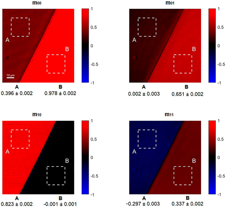
FIGURE 2. A Linear Polarizer (region A) and a simple microscopy glass slide (region B) have been used as reference sample. In the bottom part of the images associated with each Mueller coefficient are reported the statistics (mean and standard deviation) of the pixels inside the dashed squares (A and B) for each Mueller image.
Then, a LP and a HWP have been placed in the focal plane of the microscope and rotated using a rotating holder. These characterizations have been carried out to validate the technique since these two samples are exhibiting the two physical properties (Dichroism and Birefringence) that can be sensed with this method. Each experimental point (blue square) results from the averaging of a whole image associated with its respective Mueller coefficients, for a specific orientation of the optics. The experimental results follow the behaviour expected by the theory even if some residual discrepancy is influencing the comparison between the theoretical plot and the experimental points (Figure 3).
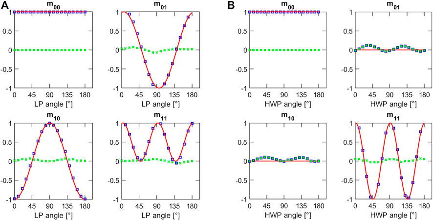
FIGURE 3. Values of the Mueller coefficients as function of the azimuthal angle of (A) the linear polarizer on the left and (B) the half-wave plate on the right. Blue squares are showing the experimental results, red lines are the fit curves and green crosses represent the values of residuals i.e., the deviation of the experimental values with respect to the theoretical prediction.
The influence of the optical elements in the microscope setup may explain the error that could be modelled as an imperfect polarization excitation of the sample. Small dichroic response of the mirrors and residual birefringence in the optical elements in the microscope may perturb the polarization state of the light coming from the ZL: so, the light effectively impinging on the sample could not be perfectly modelled with the expression state by Eq. 4 anymore. Anyway, the discrepancy is not so relevant as to compromise the imaging performance of the microscopy setup: of course, without any alteration, the polarization contrast will be sharper but since its degradation is modest, the setup can provide imaging contrast as well. The good results of these characterizations confirmed the possibility to measure these coefficients by exploiting the polarization encoded in the Zeeman Beating Line.
3.2 Biological Samples: Starch and Collagen Fibers
The label-free imaging capabilities have been tested on organic samples well known for their clear response to polarized light. The pixel-dwell time used for the following acquisitions has been set equal to 10.8 μs, allowing full recordings of a 512 × 512 pixels image in less than 3 s with our scanning microscopy setup. Figure 4A represents the results on starch granules embedded in potato cells: the m00 image is showing the total transmitted intensity of the light and it allows to see the clear shape and the outline of the granules. The m01 coefficient is related to the linear dichroism and it is possible to see the red-blue alternation within each starch granule, associated with positive-negative values of its pixels: this is a typical response for this kind of sample, showing a different molecular arrangement in the different regions of the starch granules.
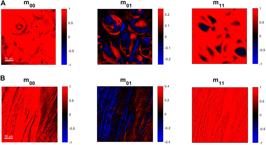
FIGURE 4. 512 × 512 pixels images obtained from the Zeeman laser method implemented into an optical scanning beam architecture associated with the Mueller coefficients obtained by the analysis of the Zeeman Beating signal. (A) Images of starch granules from a potato thin-cut slice. (B) Images of collagen fibres from a rat knee.
Another interesting sample studied with polarized light is collagen fibres: in Figure 4B we report images of collagen fibres coming from ligaments of rat. The fibres orientation provides a strong contrast to linear dichroism in Mueller Matrix imaging, as is shown by the different colours in the collagen fibres that are linked to their orientation and arrangement. So, the fast modulation of the polarization state in combination with the microscopy setup can be effectively used to study orientation and compactness in this kind of sample.
4 Conclusion
Mueller Matrix microscopy is an inherent label-free multimodal imaging approach since it can provide several contrast mechanisms depending on the specific component of polarization response. Among the wide variety of techniques implemented for this imaging method, few of them can deal with the short pixel dwell time in fast scanning microscopy configuration. Here we demonstrated the ZL can satisfy this requirement and it can simplify the setup since the role of the light stage and the PSG are merged in a single device. The performance of this setup has been validated with polarization optics and images of biological samples with a clear structure exhibiting contrast to polarized light have been presented. The polarization encoded in the 700 kHz beating signal coming from the analysis of the light emitted from the Zeeman Laser, allows to match the speed requirement of a scanning microscope: indeed, imaging with pixel-dwell time around 10 μs have been demonstrated. This technology, based on the heterodyne detection of the optical components of a dual-frequency, dual-polarization laser, can be further improved by increasing the magnitude of the magnetic field in the active medium, to increase the value of the beating frequency, or with a different DFDP light source. The sharp polarization-based contrast, combined with the imaging speed enabled by this setup, allows performing fast label-free acquisition with scanning microscopy platforms, which are essential tools to perform imaging of biological specimens. Moreover, the absence of any dedicated stage for the tailoring of the polarization state simplifies the build-up of the setup, since it allows to get rid of complex optical alignment and the use of additional external devices. We believe that this method will pave the way to real-time Mueller Matrix imaging, further spreading its application in biological research as a label-free imaging approach.
Data Availability Statement
The raw data supporting the conclusions of this article will be made available by the authors, without undue reservation.
Author Contributions
FC, ALG and AD conceived the research. FC conducted the experiments. FC, ALG and AZ developed the theorectical background formalism, analyzed the results and wrote the manuscript. AZ, PB and AD contributed to useful discussions. All the authors reviewed and approved the manuscript.
Conflict of Interest
The authors declare that the research was conducted in the absence of any commercial or financial relationships that could be construed as a potential conflict of interest.
Publisher’s Note
All claims expressed in this article are solely those of the authors and do not necessarily represent those of their affiliated organizations, or those of the publisher, the editors and the reviewers. Any product that may be evaluated in this article, or claim that may be made by its manufacturer, is not guaranteed or endorsed by the publisher.
Acknowledgments
We want to thank S. Surdo for the help with the Stabilization Unit electronics, P. Saggau for the scientific discussion and proofreading and S. M. Goldwasser for the excellent online material on the development of a Zeeman Laser.
Supplementary Material
The Supplementary Material for this article can be found online at: https://www.frontiersin.org/articles/10.3389/fphy.2021.758880/full#supplementary-material
References
1. Diaspro A, Bertolotto M, Vergani L, Nicolini C. Polarized Light Scattering of Nucleosomes and Polynucleosomes—In Situ and In Vitro Studies. IEEE Trans Biomed Eng (1991) 38(7):670–8. doi:10.1109/10.83568
2. Bickel WS, Davidson JF, Huffman DR, Kilkson R. Application of Polarization Effects in Light Scattering: a New Biophysical Tool. Proc Natl Acad Sci (1976) 73(2):486–90. doi:10.1073/pnas.73.2.486
3. Tinoco I, Mickols W, Maestre MF, Bustamante C. Absorption, Scattering, and Imaging of Biomolecular Structures with Polarized Light. Annu Rev Biophys Biophys Chem (1987) 16:319–49. doi:10.1146/annurev.bb.16.060187.001535
4. Le Gratiet A, Mohebi A, Callegari F, Bianchini P, Diaspro A. Review on Complete Mueller Matrix Optical Scanning Microscopy Imaging. Appl Sci (2021) 11(4):1–18. doi:10.3390/app11041632
5. Fujiwara H. Spectroscopic Ellipsometry: Principles and Applications. Chichester, England: John Wiley & Sons Ltd (2007). p. 1–369.
6. Lu SY, Chipman RA. Mueller Matrices and the Degree of Polarization. Opt Commun (1998) 146(1–6):11–4. doi:10.1016/s0030-4018(97)00554-3
7. Le Gratiet A, Pesce L, Oneto M, Marongiu R, Zanini G, Bianchini P, et al. Circular Intensity Differential Scattering (CIDS) Scanning Microscopy to Image Chromatin-DNA Nuclear Organization. OSA Continuum (2018) 1(3):1068. doi:10.1364/osac.1.001068
8. Marongiu R, Le Gratiet A, Pesce L, Bianchini P, Diaspro A. ExCIDS: a Combined Approach Coupling Expansion Microscopy (ExM) and Circular Intensity Differential Scattering (CIDS) for Chromatin-DNA Imaging. OSA Continuum (2020) 3(7):1770. doi:10.1364/osac.388868
9. Le Gratiet A, d'Amora M, Duocastella M, Marongiu R, Bendandi A, Giordani S, et al. Zebrafish Structural Development in Mueller-Matrix Scanning Microscopy. Sci Rep (2019) 9(1):19974–10. doi:10.1038/s41598-019-56610-9
10. Le Gratiet A, Dubreuil M, Rivet S, Le Grand Y. Scanning Mueller Polarimetric Microscopy. Opt Lett (2016) 41(18):4336. doi:10.1364/ol.41.004336
11. Zeeman P. The Effect of Magnetisation on the Nature of Light Emitted by a Substance. Nature (1897) 55:347. doi:10.1038/055347a0
12. Shigeoka T, Imanishi S, Kawata S. Development of a Beat Frequency Tunable Stabilized Axial Zeeman Laser. Jpn J Appl Phys Part 1 Regul Pap Short Notes Rev Pap. (1997) 36(5 A):2681–4. doi:10.1143/jjap.36.2681
13. Baer T, Kowalski FV, Hall JL. Frequency Stabilization of a 0633-μm He-Ne Longitudinal Zeeman Laser. Appl Opt (1980) 19(18):3173. doi:10.1364/ao.19.003173
14. Takasaki H, Umeda N. Stabilized Transverse Zeeman Laser. Rev Laser Eng (1981) 9(1):11–20. doi:10.2184/lsj.9.11
15. Takasaki H, Umeda N, Tsukiji M. Stabilized Transverse Zeeman Laser as a New Light Source for Optical Measurement. Appl Opt (1980) 19(3):435. doi:10.1364/ao.19.000435
16. Javan A, Bennett WR, Herriott DR. Population Inversion and Continuous Optical Maser Oscillation in a Gas Discharge Containing a He-Ne Mixture. Phys Rev Lett (1961) 6(3):106–10. doi:10.1103/physrevlett.6.106
17. Paananen R, Tang CL, Statz H. Zeeman Effects in Gaseous He-Ne Optical Masers. Proc IEEE (1963) 51(1):63–9. doi:10.1109/proc.1963.1660
18. McClain WM, Jeng W-H, Pati B, Shi Y, Tian D. Measurement of the Mueller Scattering Matrix by Use of Optical Beats from a Zeeman Laser. Appl Opt (1994) 33(7):1230. doi:10.1364/ao.33.001230
Keywords: zeeman laser, mueller matrix microscopy, label-free, polarization, optical scanning microscopy, laser
Citation: Callegari F, Le Gratiet A, Zunino A, Mohebi A, Bianchini P and Diaspro A (2021) Polarization Label-Free Microscopy Imaging of Biological Samples by Exploiting the Zeeman Laser Emission. Front. Phys. 9:758880. doi: 10.3389/fphy.2021.758880
Received: 15 August 2021; Accepted: 05 October 2021;
Published: 22 October 2021.
Edited by:
Nirmal Mazumder, Manipal Academy of Higher Education, IndiaReviewed by:
Hui Ma, Tsinghua University, ChinaNaveen Nishchal, Indian Institute of Technology Patna, India
Copyright © 2021 Callegari, Le Gratiet, Zunino, Mohebi, Bianchini and Diaspro. This is an open-access article distributed under the terms of the Creative Commons Attribution License (CC BY). The use, distribution or reproduction in other forums is permitted, provided the original author(s) and the copyright owner(s) are credited and that the original publication in this journal is cited, in accordance with accepted academic practice. No use, distribution or reproduction is permitted which does not comply with these terms.
*Correspondence: Alberto Diaspro, YWxiZXJ0by5kaWFzcHJvQGlpdC5pdA==