- 1Key Laboratory of Artificial Structures and Quantum Control, School of Physics and Astronomy, Shanghai Jiao Tong University, Shanghai, China
- 2Institute of Applied Physics and Computational Mathematics, Beijing, China
High-performance terahertz (THz) imaging devices have drawn wide attention due to their significant application in a variety of application fields. Recently, the upconversion device based on the integrated homo-junction interfacial workfunction internal photoemission detector and light-emitting diode (HIWIP-LED) has emerged as a promising candidate for broadband THz upconversion pixelless imaging device. In this paper, systematical investigations on the cryogenic-temperature performances of the LED part in HIWIP-LED devices, including electroluminescence (EL) spectra and the EL efficiency, have been carried out by elaborating the radiative recombination mechanism in the quantum well, internal quantum efficiency, and the light extraction efficiency (LEE) both experimentally and theoretically. On this basis, we have further studied the operation mode of the HIWIP-LED and concluded that the LEE could directly determine the upconversion efficiency. A numerical simulation has been performed to optimize the LEE. Numerical results show that the device with a micro-lens geometry structure could significantly improve the LEE of the LED thereby increasing the upconversion efficiency. An optimal upconversion efficiency value of 0.12 W/W and a minimum noise equivalent power (NEP) of 14 pW/Hz1/2 are achieved using the micro-lens structure together with anti-reflection coating. This work gives a precise description of cryogenic LED performance in the HIWIP-LED device and provides an optimization method for the broadband HIWIP-LED THz upconversion pixelless imaging device.
Introduction
Up-converting long-wavelength infrared (IR) light to shorter-wavelength radiation has attracted more attention and has been intensively explored in the last two decades thanks to its tremendous potential in low-cost and large-format IR/terahertz (THz) imaging, high-efficiency solar cells, and sensitive biological imaging [1–4]. Among many upconversion methods, semiconductor up-conversion technology is extremely competitive due to its compactness, high efficiency, flexible and adjustable response frequency, and full compatibility with semiconductor manufacturing processes [4]. This idea was proposed and realized by H. C. Liu in 1995 with an integrated up-conversion device comprising a quantum well IR photodetector (QWIP) and a light-emitting diode (LED) [5]. The IR signal at the range of 8–12 μm was first detected by the QWIP, and then the produced photocurrent was injected into the active region of the LED resulting the extra near infrared (NIR) emission under bias voltage [5, 6]. When used for a large-format imaging device, the integrated device converts the incoming IR image into an outgoing NIR or visible image which then is captured by a Si charge-coupled device (CCD). There is no separate pixel in this imaging scheme, and this pixelless imaging technology could realize large-format two-dimensional IR imaging easily without the need for the Si readout integrated circuits (ROIC) on the chip and without the need for the hybrid bonding process. This imaging method also avoids the thermal mismatch problem between the focal plane array (FPA) chip and Si ROIC in the large-format hybrid QWIP FPAs at cryogenic temperatures [6].
Variable upconversion devices have been realized at the ranges of the NIR, mid-infrared (MIR), and THz based on the concept of integrated photodetector and LED [7–13]. At MIR range, the QWP-LEDs are well developed, and a high-temperature resolution for the n-type QWP-LED of 60 mK was successfully realized [14]. In contrast, the relative backwardness of the THz upconversion pixelless imaging demands great effort and further exploration. Due to the diffraction limit and the limitation of low-temperature operation, the THz FPAs based on photon-type detectors has not made significant progress so far. The pixelless imaging provides a good alternative for photon-type THz imaging. THz QWP-LED prototype device was successfully fabricated to upconvert the 4.2 THz radiation from a quantum cascade laser into an 830 nm NIR emission in 2016 [9]. However, the edge coupled optical coupling geometry adopted in the device to excite the intersubband transition caused a severe distortion of the imaging QCL spot. Therefore, this THz QWP-LED pixelless imaging device is far from an optimization for the thermal imaging. The upconversion device based on the homo-junction interfacial workfunction internal photoemission (HIWIP) detector and LED allows normal incidence excitation and realizes a broadband (4–20 THz) THz to NIR upconversion [15]. However, the current limiting factor for this imaging scheme is the low upconversion efficiency. In fact, the problem of low upconversion efficiency also plagues almost all III-V compound semiconductor based upconversion devices. The upconversion efficiency of the MIR or THz upconverter are all below the level of 0.01 W/W [15–17], which greatly restrains the efficiency and quality of the pixelless imaging. How to improve the upconversion efficiency is an urgent problem for HIWIP-LED pixelless imaging devices. And in the past, people paid more attention to the room temperature performance of LEDs. The performance of LEDs at extremely low temperatures (<20 K) is not particularly clear.
In this paper, we present the experimental results of the LED in the HIWIP-LED device at different temperatures and provide the explanation of the variation of temperature-dependent emission spectra by numerically solving the Schrodinger equation. The internal quantum efficiency and light extraction efficiency (LEE) of the LED are determined using a developed rate equation method, which reveals that the low LEE is the main reason to cause the low upconversion efficiency of HIWIP-LED. The device structure and operation mode of the HIWIP-LED are investigated systematically to further elaborate the upconversion mechanism, bias voltage distribution, and the primary determinant of the upconversion efficiency. Finally, a numerical simulation is carried out to improve the LEE of the LED portion, and the results show that the upconversion efficiency for HIWIP-LED could be enhanced one order of magnitude using the micro-lens structure LED. This work makes us have a clearer understanding of the low-temperature performance of HIWIP-LED and provides theoretical guidance for the experiments to improve upconversion efficiency.
Device and Upconversion Principle
The device structure of HIWIP-LED is shown in Figure 1A, which consists of a GaAs-based HIWIP detector and an InGaAs/GaAs/AlGaAs quantum well LED directly grown by molecular beam epitaxy (MBE). The active region of the p-type GaAs HIWIP detector consists of 20 repeats of p-GaAs (doped with Be to 3 × 1018 cm−3)/i-GaAs (emitter layer/intrinsic) layers with emitter layer and intrinsic layer thickness of 80 and 15 nm. The quantum well LED structure is 9 nm In0.1Ga0.9As quantum well sandwiched by 40 nm intrinsic GaAs. On either side of the GaAs are 80 nm AlxGa1-xAs barriers in order to enhance the carrier confinement effect and increase the internal quantum efficiency of LED. The top AlxGa1-xAs grading barrier (
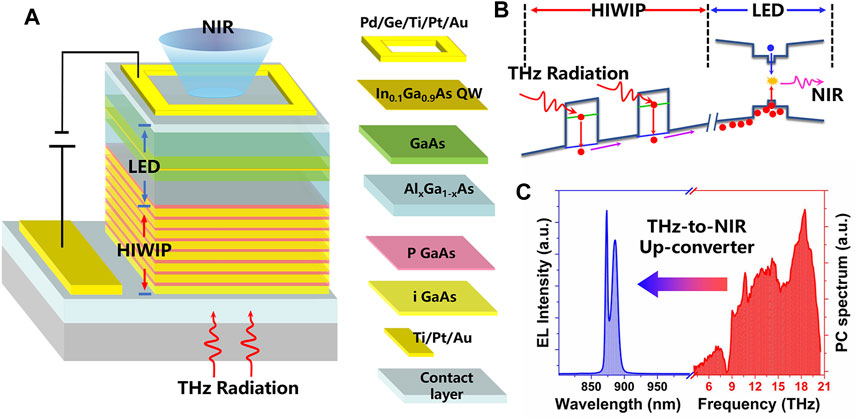
FIGURE 1. (A) Device structure of HIWIP-LED. (B) Micro-mechanism of the upconversion process of the HIWIP-LED: THz absorption occurred in the emitter layers of the HIWIP followed by the transportation of the carriers. The photo-excited carriers are injected into the quantum well for radiative recombination. (C) The measured cryogenic emission spectrum of the LED portion and the photocurrent spectrum of the HIWIP portion in the upconversion device at 3.5 K.
Figure 1B reveals the micro-mechanism of the upconversion process of the HIWIP-LED. THz absorption occurred in the emitter layers of the HIWIP followed by the transportation of the photo-generated carriers. The photo-excited carriers are injected into the In0.1Ga0.9As quantum well for recombination and emitting NIR photons under the external electric field. The measured cryogenic (3.5 K) emission spectrum of the LED portion and the photocurrent spectrum of the HIWIP portion in the upconversion device are displayed in Figure 1C. There are two emission peaks in the LED electroluminescence (EL) spectrum, which is due to the complexity of the valence band in the In0.1Ga0.9As quantum well and will be discussed in detail in the following section. The photocurrent spectrum presents a broadband response range from 4 to 20 THz with a peak response frequency at 18 THz. The deep valley around 8 THz is the Reststrahlen band of GaAs. The small valleys at the range from 9 to 20 THz are associated with the multiple phonon absorption.
Performance of the LED in HIWIP-LED
The EL spectra with a drive current of 1 mA at different temperatures of the LED part are presented in Figure 2A, which are measured using a fiber spectrometer (Ocean optics QE65PRO) with the same integrated time. There are two luminescence peaks at 873 (peak 1) and 887 nm (peak 2) at the temperature below 50 K. Peak 1 rises with the increasing of the driven current and presents a red-shift effect as the temperature increases. We attribute the red-shift behavior to the energy gap decreases due to the Varshni effect. Peak 2 has no position shift, and the intensity decreases with the temperature increasing. What is more interesting is that there exists a competition between peak1 and peak 2 as is shown in Figure 2B. As the temperature increases from 4.6 to 50 K, the intensity of peak 1 increases and peak 2 decreases. The luminescence wavelength of the intrinsic recombination of the GaAs barrier is at about 816 nm (the band gap of the GaAs is 1.519eV at 4.6 K). But the observed EL peaks are all above the wavelength of 816 nm, which indicates they all originate from the InGaAs quantum well. In order to understand the luminescent property of the LED, we calculated the band structure of the In0.1Ga0.9As/GaAs quantum well by solving the Schrodinger equation using the plane wave expansion (PWE) method [18, 19]:
where m* is the electron effective mass, ℏ is the reduced Planck constant, VQW is the stepwise potential energy representing the conduction band offset profile, VH is the Hartree potential energy obtained from Poisson's equation, Vxc is the exchange-correlation potential energy which is given by the local density approximation based on the density functional theory, φ is z-direction envelope function, and ε is eigen-energy. The PWE method is used for accurate calculation. The lattice mismatch caused strain, and bias-caused Stark shift is neglected. The band gaps of GaAs and In0.1Ga0.9As are taken as 1.518959 and 1.36495 eV at 4 K, respectively. The ratio of conduction and valence band offsets is set as 6:4. The effective masses of the well (
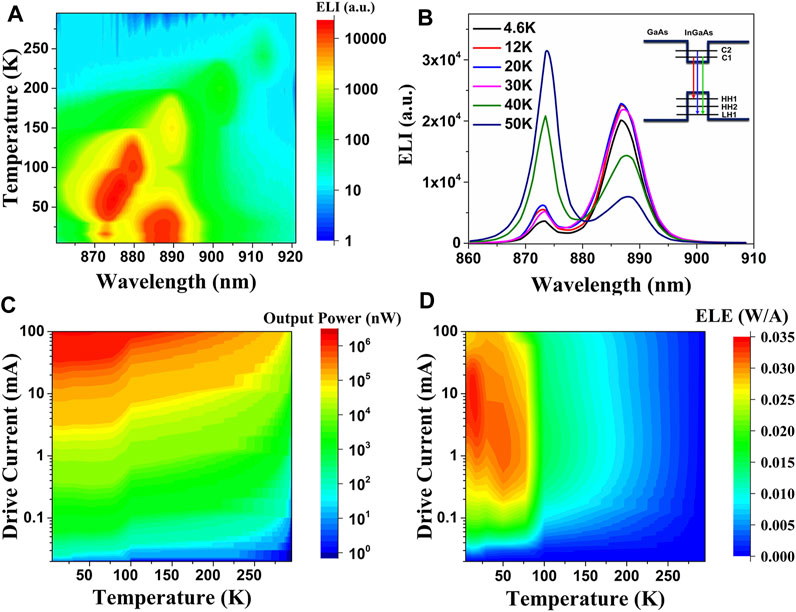
FIGURE 2. (A) Electroluminescence (EL) spectra with a drive current of 0.5 mA at different temperatures of the LED part. (B) EL intensity for the LED part with 0.5 mA drive current at a temperature below 50 K; also shown in the inset is the quantum well structure and interband transition of the LED. (C) The experimental variation of the output EL power of the LED with the bias and temperature. (D) The mapping result of the EL efficiency (ELE) as a function of drive current and temperature.
According to our calculated results (inset of Figure 2B), peak 2 at 887 nm is related to the first conduction subband to the first heavy hole subband transition (
The experimental variation of the output EL power of the LED with the bias and temperature is shown in Figure 2C. We find that the output power increases with the drive current and decreases with temperature. The electroluminescence efficiency (ELE) is defined as output power divided by the drive current and is proportional to the external quantum efficiency (EQE) of the LED. The mapping result of the ELE as a function of drive current and temperature is presented in Figure 2D, which indicates an evident ELE drop when the temperature increases from 4 to 300 K at any drive current. The ELE increases first and then decreases with the drive current at the same temperature. The efficiency drop with larger injection current is mainly caused by the increase of the nonradiative recombination (SRH recombination and Auger recombination) [21, 22]. The peak point of the ELE shifts to lower current as temperature increases because the nonradiative recombination increases sharply with temperature.
A rate equation analysis method developed by Ray et al. can describe the injection current dependence of the LED external efficiency explicitly by numerically solving the following equation (23):
where ηi is the internal quantum efficiency (IQE), J is the injection current density, and ηmax and Jmax are the maximum value of IQE and the corresponding injection current density (see the Supplementary Materials for ABC model and rate equation analysis method). Figure 3A shows the injection current density-dependent internal efficiency of the LED at 30, 50, and 77 K, respectively. The fitting results from rate equation analysis method indicate the maximum IQE of 93%, 95%, and 87.5% at the temperatures of 33, 50, and 77 K, respectively. Using this method, the ηmax and corresponding Jmax at different temperatures are given in Figure 3B. The ηmax at low temperatures are relatively lower than that of higher temperature mainly because of the incomplete ionization of the doping acceptor Be. The Jmax values at low temperature also indicate the need for a larger injection current to realize the ηmax owing to the incomplete ionization. The inset of Figure 3B also presents the measured external efficiency of the LED at different temperatures with the same injection current (500 μA), which agree well with the integrated EL results. If we neglect the influence of temperature, the LEE of the LED is calculated to be about 2.5% at temperature below 100 K (Figure 3C) from the relation of
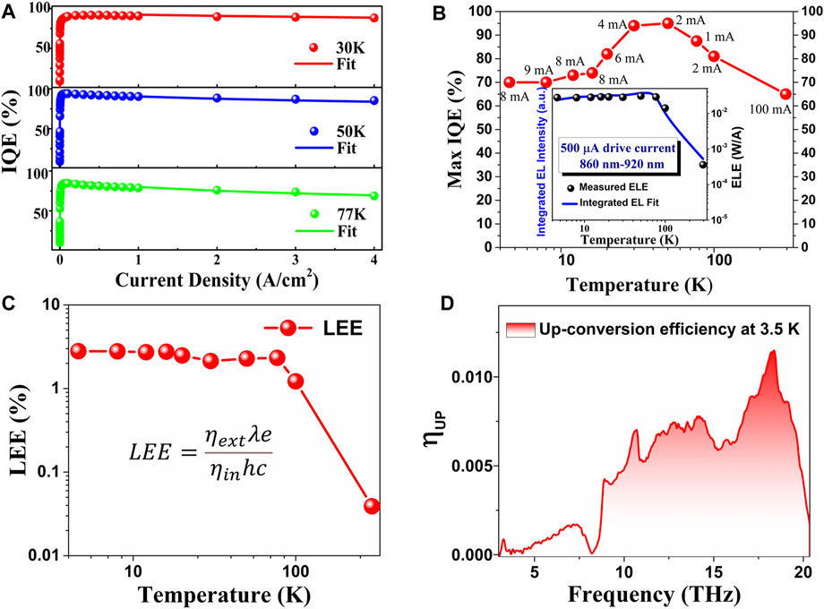
FIGURE 3. (A) Injection current density-dependent internal efficiencies and the fit results of the LED at 30, 50, and 77 K, respectively. (B) ηmax and corresponding Jmax at different temperatures, and the inset is the measured external efficiency of the LED at different temperatures with the same injection current (0.5 mA). (C) The calculated light extraction efficiency (LEE) at different temperatures. (D) Calculated upconversion efficiency with a bias voltage of 1.8 V.
Theoretical Optimization of LED
In order to improve the energy conversion efficiency of the HIWIP-LED, we should have a greater awareness of the operation principle of the HIWIP-LED. Figure 4A shows the calculated band diagram across the layer structure of the HIWIP-LED upconversion device under the bias of 0 and 3 V, with the top contact being grounded. The calculation was carried out under the assumption that the band alignment of the heterostructure (GaAs/AlxGa1-xAs or GaAs/InGaAs) follows Anderson's electron affinity rule and the TCAD-based approach is used. We find that the applied bias voltage drops mainly across the LED part, and then the additional bias voltage goes to the HIWIP part. This feature gives rise to a turn-on behavior of the HIWIP-LED device, which is in good agreement with the observed results in the previous experimental measurement [15].
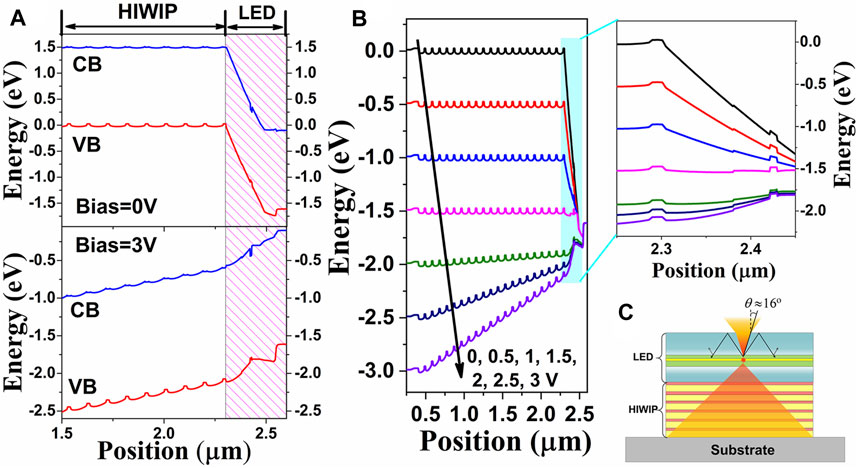
FIGURE 4. (A) Calculated band diagram across the layer structure of the HIWIP-LED upconversion device under the bias of 0 and 3 V, with the top contact being grounded. (B) Calculated results of the valence band diagram under different bias voltage with the larger version of the LED band diagram. (C) Schematic diagram of the total internal reflection and critical angle at the air/semiconductor interface.
The calculation results of the valence band diagram under different bias voltage are displayed in Figure 4B. It is evident that little bias falls across the HIWIP side when the applied bias voltage is lower than 1.5 V, which is equal numerically to the turn-on voltage in the p-i-n structure of the LED. This feature is clear in the larger version of the LED band diagram, which indicates that the applied bias first overcomes the depletion region of the LED and then the other portion of the bias is applied to the HIWIP portion. It should be noted that we did not take the incident radiation into account during the calculation, but the conclusion is still valid when the device is illuminated by the THz radiation. Indeed, the HIWIP is a photoconductor so that the THz excitation of the detector will decrease the resistance of the HIWIP and thereby increase the bias voltage dropped across the LED portion, leading to an increase in the LED emission intensity. Since there is no internal electrical gain inside the HIWIP-LED, the upconversion efficiency could be expressed as
It has been reported that artificial nano- or micro-photonic structures or textured structures on the top of optoelectronic devices can help with light coupling [29, 30]. Wet chemical etching and photoelectrochemical etching can be used to create a substantial amount of surface roughness on III-V semiconductors. These etches are always crystallographic in nature, which makes the textured surface display pyramid-like structures. Both of the nano-pyramid and micro-pyramid have been widely used in photovoltaics, and the pyramid structure is proposed as both the light-trapping and antireflection technique to enhance the solar photon absorption of Si- or GaAs-based solar cells [31]. Conversely, if the textured surface or pyramid structure was used in light-emitting devices, the LEE will be significantly improved. Another coupling approach is the micro-lens on the top of the LED, which is also widely used in commercial LEDs as miniaturized extractors. The advantage of the micro-lens is that the critical angle increases from a small value to near 180°, and the influence of the internal total reflection is greatly reduced. Here, we carried out the 3D optical simulations with finite difference time domain (FDTD) method to calculate the LEE for devices with different geometries (micro-pyramid arrays and micro-lens arrays). Meanwhile, for the sake of comparison, the planar device structure and the planar structure with SiO2 anti-reflection optical coating (thickness of the SiO2 film is set as a quarter of the emitted wavelength) were also modeled (see the Supplementary Materials for simulation parameter settings and descriptions). The LED devices with different geometries are shown in Figures 5A–D, below which are the cross-sectional electric field intensities (|E|) for the corresponding geometries. The wavelength of the dipole source is set as 870 nm, and the periodic boundary condition is used.
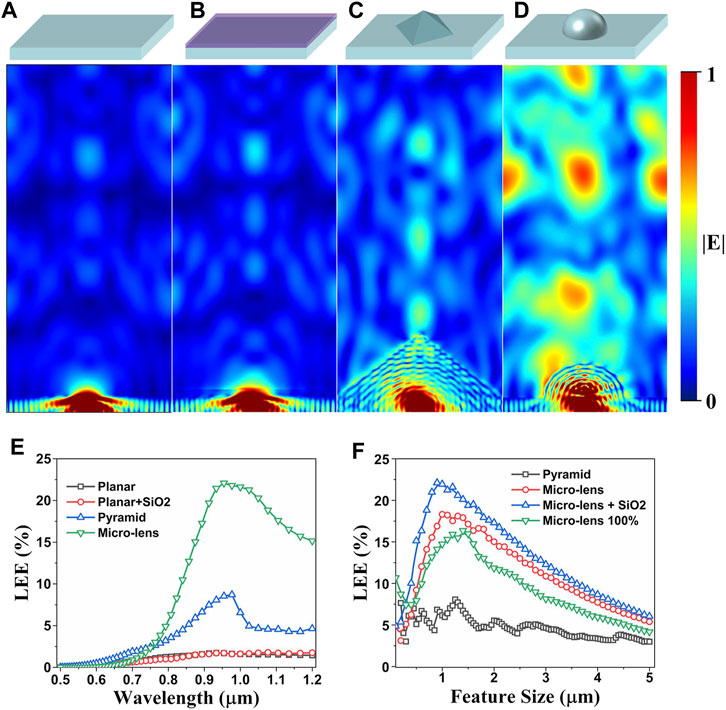
FIGURE 5. The schematic diagram of the LED device with different geometries, also showing the corresponding optical distribution for the same dipole source with a certain wavelength of 870 nm. (A) Planar structure. (B) Planar structure with SiO2 AR coating. (C) Micro-pyramid structure. (D) Micro-lens structure. (E) The calculated LEE as a function of the emitting wavelength for the devices with different geometries. (F) Optimization results for the pyramid and micro-lens structure. The feature size corresponds to the bottom side length of the pyramid or the radius of the hemi-sphere-like micro-lens.
It is easy to see that most of the light is confined inside the planar device in Figures 5A, B, which exhibits the |E| intensity for the device with SiO2 anti-reflection optical coating, which presents a little enhancement of the LEE, although the result is not obvious. Figure 5C shows the |E| intensity for the device with the micro-pyramid arrays geometry; apparently the LEE of the device is improved, and more photons could escape from the active region of the LED. Figure 5D displays the |E| intensity for the device with the micro-lens arrays geometry; the significantly enhanced radiative propagation means that a large number of the photons could be extracted out of the device and the LEE is greatly improved. The calculated LEE as a function of the emitting wavelength for the devices with different geometries is shown in Figure 5E. The simulation periods are set as 4 μm for all the geometries, and the bottom side length of the pyramid and the radius of the hemisphere-like micro-lens are set as 1 μm. The simulation results reveal that the anti-reflective (AR) coating contributes a little to the LEE. The maximum LEE is improved five times in the micro-pyramid structure at the wavelength of 970 nm. And the micro-lens structure improves the LEE by one order of magnitude compared with the planar structure. For a certain emitting wavelength (870 nm), the pyramid and micro-lens structure should be optimized to maximize the LEE. Figure 5F gives the optimization results for the pyramid and micro-lens structure. The feature size corresponds to the bottom side length of the pyramid or the radius of the hemisphere-like micro-lens. The duty ratio for the pyramid (bottom side length to the period length) and micro-lens (diameter to the period length) are set as 100% and 50%, respectively. The micro-lens 100% represents the duty ratio which is set as 100%. It could be found that the micro-lens with a radius about 1 μm and a 50% duty ratio can effectively enhance the LEE, which increases to a factor of 2.5 compared with the pyramid structure. If the AR coating was applied in the micro-lens structure, the LEE will be further improved.
On the basis of the above simulation, the upconversion efficiency for the devices with different geometries could be determined. The calculated upconversion efficiencies for the devices with planar structure, micro-pyramid, micro-lens, and micro-lens combined with AR coating are shown in Figure 6A. We can find that the upconversion efficiency for the device with the micro-lens structure and SiO2 AR coating is improved by an order of magnitude compared with the planar structure. The noise equivalent power (NEP) is a figure of merit for photodetectors. Figure 6B shows the calculated NEPs under different bias voltages at 3.5 K for the upconversion imaging system with the optimal micro-lens structure and SiO2 AR coating using Eq. 3.
where ηSi is the quantum efficiency of the Si CCD at the luminescence wavelength of the LED; ηLED is the external quantum efficiency of the LED, which is determined by the internal quantum efficiency and the LEE simultaneously; e is the elementary charge; gHW is the gain in the HIWIP; ibg is the background photocurrent of the 300 K radiation; idark is the device dark current;
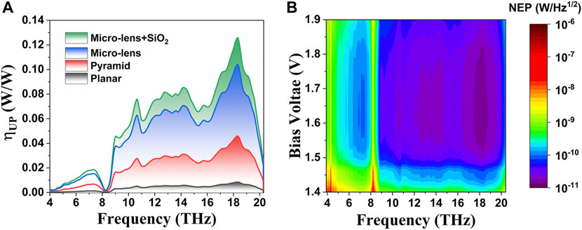
FIGURE 6. (A) The calculated upconversion efficiencies for the devices with planar structure, micro-pyramid, micro-lens, and micro-lens combined with AR coating. (B) The calculated NEP under different bias voltages at 3.5 K for the upconversion imaging system with the optimal micro-lens structure and SiO2 AR coating.
The detailed calculation of the NEP could be found in the Supplementary Materials and Refs. [15, 32]. The bias voltage range start from the value of 1.4 V corresponds to the turn-on voltage of HIWIP-LED. We can find that the NEPs for all frequencies are almost below the level of 100 pWHz−1/2 and the optimal value is about 14 pWHz−1/2 at 18.4 THz in the bias range of 1.5–1.8 V. This value is close to the minimum NEP of the single HIWIP (12.4 pWHz−1/2 [15]) and about one-half smaller than that of the HIWIP-LED device with planar structure (about 29 pWHz−1/2 [15]).
Conclusion and Outlook
In this paper, we have reported a systematic investigation on the cryogenic-temperature performances of the LED part in HIWIP-LED devices, including EL spectra and the EL efficiency. Numerical calculations have been carried out to elaborate the radiative recombination mechanism in the quantum well and explain the internal quantum efficiency as well as the LEE. On this basis, we have further studied the operation mode of the HIWIP-LED and concluded that the LEE is the determining factor of the upconversion efficiency. Then, a numerical simulation has been performed to optimize the LEE. The calculated results show that a device with the micro-lens geometry structure could significantly improve the LEE of the LED thereby increasing the upconversion efficiency. An optimal upconversion efficiency value of 0.12 W/W and minimum NEP of 14 pW/Hz1/2 are achieved using the micro-lens structure together with anti-reflection coating. This work not only gives the experimental results and theoretical explanations of LEDs at low temperatures but also clarifies that for a given upconversion device, the most direct way to improve the upconversion efficiency is to increase the LEE at the LED portion. The surface micro-lens coupling structure we proposed can increase the upconversion efficiency of HIWIP-LED by an order of magnitude, and the corresponding imaging performance NEP can be reduced to one-half of the previous value, which is a good improvement. Our theoretical work provides guidance for the experimental research of pixelless imaging. In addition, the working mechanism of the upconverter and the method of improving upconversion efficiency clarified in this article are also applicable to other MIR or NIR upconversion devices based on III-V compound semiconductors. This means that the efficiency of MIR and NIR upconversion devices and corresponding pixelless imaging performance will also be further improved, which is important for the development of larger area, higher resolution, and low-cost IR and THz imaging devices.
Data Availability Statement
The raw data supporting the conclusions of this article will be made available by the authors, without undue reservation.
Author Contributions
PB performed the research and wrote the paper. YZ and WS proposed the concept. YZ and WC supervised the project. NY contributed to the simulation. All authors discussed the results and co-wrote the article.
Funding
This work was supported by the Natural Science Foundation of China (12104061, U1730246, 1207424, and 911834011), Natural Science Foundation of Shanghai (19ZR1427000), Project funded by China Postdoctoral Science Foundation (2020M680458), and Open Project funded by Key Laboratory of Artificial Structures and Quantum Control (2020-03).
Conflict of Interest
The authors declare that the research was conducted in the absence of any commercial or financial relationships that could be construed as a potential conflict of interest.
Publisher’s Note
All claims expressed in this article are solely those of the authors and do not necessarily represent those of their affiliated organizations, or those of the publisher, the editors and the reviewers. Any product that may be evaluated in this article, or claim that may be made by its manufacturer, is not guaranteed or endorsed by the publisher.
Supplementary Material
The Supplementary Material for this article can be found online at: https://www.frontiersin.org/articles/10.3389/fphy.2021.774524/full#supplementary-material
References
1. Chen J, Tao J, Ban D, Helander MG, Wang Z, Qiu J, et al. Hybrid Organic/Inorganic Optical Up-Converter for Pixel-Less Near-Infrared Imaging. Adv Mater (2012) 24:3138–42. doi:10.1002/adma.201200587
2. Yang Y, Zhang YH, Shen WZ, Liu HC. Semiconductor Infrared Upconversion Devices. Prog Quan Electron (2011) 35:77–108. doi:10.1016/j.pquantelec.2011.05.001
3. Wu DM, García-Etxarri A, Salleo A, Dionne JA. Plasmon-enhanced Upconversion. J Phys Chem Lett (2014) 5:4020–31. doi:10.1021/jz5019042
4. Liu Q, Feng W, Yang T, Yi T, Li F. Upconversion Luminescence Imaging of Cells and Small Animals. Nat Protoc (2013) 8:2033–44. doi:10.1038/nprot.2013.114
5. Liu HC, Li J, Wasilewski ZR, Buchanan M. Integrated Quantum Well Intersub-Band Photodetector and Light Emitting Diode. Electron Lett (1995) 31:832–3. doi:10.1049/el:19950522
6. Liu HC, Allard LB, Buchanan M, Wasilewski ZR. Pixelless Infrared Imaging Device. Electron Lett (1997) 33:379–80. doi:10.1049/el:19970242
7. Liu HC, Gao M, Poole PJ. 1.5 [micro Sign]m Upconversion Device. Electron Lett (2000) 36:1300–1. doi:10.1049/el:20000915
8. Ban D, Luo H, Liu HC, Wasilewski ZR, Paltiel Y, Raizman A, et al. Midinfrared Optical Upconverter. Appl Phys Lett (2005) 86:201103. doi:10.1063/1.1921330
9. Fu ZL, Gu LL, Guo XG, Tan ZY, Wan WJ, Zhou T, et al. Frequency Upconversion Photon-type Terahertz Imager. Sci Rep (2016) 6:1–8. doi:10.1038/srep25383
10. Ban D, Luo H, Liu HC, SpringThorpe AJ, Glew R, Wasilewski ZR, et al. 1.5 to 0.87 [micro Sign]m Optical Upconversion Device Fabricated by Wafer Fusion. Electron Lett (2003) 39:1145–7. doi:10.1049/el:20030732
11. Luo H, Ban D, Liu HC, SpringThorpe AJ, Wasilewski ZR, Buchanan M, et al. 1.5 μm to 0.87 μm Optical Upconversion Using Wafer Fusion Technology. J Vac Sci Technol A (2004) 22(3):788–91. doi:10.1116/1.1689300
12. Ban D, Han S, Lu ZH, Oogarah T, SpringThorpe AJ, Liu HC. Near-infrared to Visible Light Optical Upconversion by Direct Tandem Integration of Organic Light-Emitting Diode and Inorganic Photodetector. Appl Phys Lett (2007) 90:093108. doi:10.1063/1.2710003
13. Ban D, Han S, Lu ZH, Oogarah T, SpringThorpe AJ, Liu HC. Organic-Inorganic Hybrid Optical Upconverter. IEEE Trans Electron Devices (2007) 54:1645–50. doi:10.1109/TED.2007.898462
14. Dupont E, Byloos M, Oogarah T, Buchanan M, Liu HC. Optimization of Quantum-Well Infrared Detectors Integrated with Light-Emitting Diodes. Infrared Phys Tech (2005) 47:132–43. doi:10.1016/j.infrared.2005.02.018
15. Bai P, Zhang Y, Wang T, Fu Z, Shao D, Li Z, et al. Broadband THz to NIR Upconversion for Photon-type THz Imaging. Nat Commun (2019) 10:1–9. doi:10.1038/s41467-019-11465-6
16. Allard LB, Liu HC, Buchanan M, Wasilewski ZR. Pixelless Infrared Imaging Utilizing a P-type Quantum Well Infrared Photodetector Integrated with a Light Emitting Diode. Appl Phys Lett (1997) 70:2784–6. doi:10.1063/1.119058
17. Dupont E, Byloos M, Gao M, Buchanan M, Song C-Y, Wasilewski ZR, et al. Pixelless thermal Imaging with Integrated Quantum-Well Infrared Photodetector and Light-Emitting Diode. IEEE Photon Technol Lett (2002) 14:182–4. doi:10.1109/68.980504
18. Zhang S, Wang TM, Hao MR, Yang Y, Zhang YH, Shen WZ, et al. Terahertz Quantum-Well Photodetectors: Design, Performance, and Improvements. J Appl Phys (2013) 114:194507. doi:10.1063/1.4826625
19. Jia JY, Wang TM, Zhang YH, Shen WZ, Schneider H. High-temperature Photon-Noise-Limited Performance Terahertz Quantum-Well Photodetectors. IEEE Trans Thz Sci Technol (2015) 5:715–24. doi:10.1109/TTHZ.2015.2453632
20. Ban D, Luo H, Liu HC, Wasilewski ZR, SpringThorpe AJ, Glew R, et al. Optimized GaAs∕AlGaAs Light-Emitting Diodes and High Efficiency Wafer-Fused Optical Upconversion Devices. J Appl Phys (2004) 96:5243–8. doi:10.1063/1.1785867
21. Piprek J. Efficiency Droop in Nitride-Based Light-Emitting Diodes. Phys Stat Sol (A) (2010) 207:2217–25. doi:10.1002/pssa.201026149
22. Bai P, Zhang Y, Wang T, Shi Z, Bai X, Zhou C, et al. Cryogenic Characteristics of GaAs-Based Near-Infrared Light Emitting Diodes. Semicond Sci Technol (2020) 35:035021. doi:10.1088/1361-6641/ab6dbf
23. Ryu H-Y, Kim H-S, Shim J-I. Rate Equation Analysis of Efficiency Droop in InGaN Light-Emitting Diodes. Appl Phys Lett (2009) 95:081114. doi:10.1063/1.3216578
24. Zheng MM, Zhang YH, Shen WZ. Performance Optimization of Resonant Cavity Enhanced N-GaAs Homojunction Far-Infrared Detectors: A Theoretical Study. J Appl Phys (2009) 105:084515. doi:10.1063/1.3116726
25. Zhang YH, Luo HT, Shen WZ. Demonstration of Bottom Mirrors for Resonant-Cavity-Enhanced GaAs Homojunction Far-Infrared Detectors. Appl Phys Lett (2003) 82:1129–31. doi:10.1063/1.1553992
26. Bai P, Zhang YH, Guo XG, Fu ZL, Cao JC, Shen WZ. Realization of the High-Performance THz GaAs Homojunction Detector below the Frequency of Reststrahlen Band. Appl Phys Lett (2018) 113:241102. doi:10.1063/1.5061696
27. Schnitzer I, Yablonovitch E, Caneau C, Gmitter TJ. Ultrahigh Spontaneous Emission Quantum Efficiency, 99.7% Internally and 72% Externally, from AlGaAs/GaAs/AlGaAs Double Heterostructures. Appl Phys Lett (1993) 62:131–3. doi:10.1063/1.109348
28. Dupont E, Gao M, Buchanan M, Wasilewski ZR, Liu HC. Optimization of P-Doping in GaAs Photon-Recycling Light-Emitting Diodes Operated at Low Temperature. Semicond Sci Technol (2001) 16:L21–L23. doi:10.1088/0268-1242/16/5/101
30. Zhmakin AI. Enhancement of Light Extraction from Light Emitting Diodes. Phys Rep (2011) 498:189–241. doi:10.1016/j.physrep.2010.11.001
31. Shin S-R, Lee HB, Jin W-Y, Ko K-J, Park S, Yoo S, et al. Improving Light Extraction of Flexible OLEDs Using a Mechanically Robust Ag Mesh/ITO Composite Electrode and Microlens Array. J Mater Chem C (2018) 6:5444–52. doi:10.1039/C8TC01415A
Keywords: broadband upconversion, THz pixelless imaging, light extraction efficiency (LEE), internal photoemission (IPE), light-emitting diode (LED)
Citation: Bai P, Zhang Y, Shen W, Yang N and Chu W (2021) Optimization of the Cryogenic Light-Emitting Diodes for High-Performance Broadband Terahertz Upconversion Imaging. Front. Phys. 9:774524. doi: 10.3389/fphy.2021.774524
Received: 12 September 2021; Accepted: 12 October 2021;
Published: 11 November 2021.
Edited by:
Yingxin Wang, Tsinghua University, ChinaReviewed by:
Xuguang Guo, University of Shanghai for Science and Technology, ChinaTongyi Zhang, Xian Institute of Optics and Precision Mechanics (CAS), China
Copyright © 2021 Bai, Zhang, Shen, Yang and Chu. This is an open-access article distributed under the terms of the Creative Commons Attribution License (CC BY). The use, distribution or reproduction in other forums is permitted, provided the original author(s) and the copyright owner(s) are credited and that the original publication in this journal is cited, in accordance with accepted academic practice. No use, distribution or reproduction is permitted which does not comply with these terms.
*Correspondence: Yueheng Zhang, eXVlaHpoYW5nQHNqdHUuZWR1LmNu; Weidong Chu, Y2h1X3dlaWRvbmdAaWFwY20uYWMuY24=
 Peng Bai
 Yueheng Zhang
 Wenzhong Shen
 Ning Yang
 Weidong Chu