 Youqi Zhang
 Rongyu Xia
 Kefu Huang2
 Zheng Li
- 1Department of Mechanics and Engineering Science, State Key Laboratory for Turbulence and Complex Systems, Peking University, Beijing, China
- 2Department of Mechanics and Aerospace Engineering, Southern University of Science and Technology, Shenzhen, China
The tunable manipulation of guided waves in plates brings out great potential applications in engineering practices, and the electromechanical coupling effects of piezoelectric material with shunting circuits have exhibited powerful tunability and flexibility for guided wave propagation. In this paper, a theoretical model is established to analyze the guided wave propagation in one-dimensional periodic piezoelectric plate constructed from a periodic array of anisotropic piezoelectric materials under periodic electrical boundary conditions. The extended Stroh formalism incorporating with the plane wave expansion method is developed to transform the wave motion equations of the periodic piezoelectric plate into a linear eigenvalue system, and a more concise and elegant solution of generalized displacement and generalized stress can be derived. There are various dispersion relations in terms of the altering electrical boundary conditions to be acquired, if the thin electrodes with shunting circuits are attached periodically to both surfaces of the piezoelectric plate. Analytical results show that the coupling of the local electric resonant mode and propagating elastic wave modes can induce hybridization bandgaps, and the bandgaps of Lamb waves and SH waves in the piezoelectric plate can be tuned by designing appropriate material polarization orientations and shunting circuits. In addition, the Bragg bandgaps can also be influenced by the external circuits. Results indicate that the proposed theoretical model can effectively analyze the performances of guided waves in periodic piezoelectric plate and provide useful theoretical guidance for designing smart wave control devices.
1 Introduction
Phononic crystals/metamaterials as kinds of artificial composite materials can achieve various fantastic performances [1–5] and have been attracting more and more attention for a wide variety of potential applications [6–11]. Especially, phononic crystals/metamaterials with anomalous dynamic characteristics can fulfill special functions, like wave resistance [12], vibration reduction [13, 14], vibration and wave motion control [15–17], which are significant for maintaining safety and stability of engineering structures. Phononic crystals are based on the Bragg scattering in periodic structures to reduce vibration and manipulate wave propagation by adjusting their band structures [18, 19], and the most concern is the Bragg bandgaps. The wavelength corresponding to the Bragg bandgap is of the same order as the lattice constant. However, metamaterials mainly focus on the locally resonant bandgaps at lower frequency range by changing the local mechanical properties, and the vibration reduction and wave propagation can be controlled at a deeply subwavelength scale [20]. Nowadays, many bandgap-based dynamic behavior altering design combine the characteristics of both phononic crystals and metamaterials [21], so there is no rigorous distinction between them.
The Bragg bandgaps of phononic crystals depend on the periodicity of the structure and are normally fixed and invariable. However, it is meaningful to design phononic crystals with tunable and controllable band structures in practical applications [22]. Consequently, multi-physics coupling phononic crystals have been introduced to manipulate the performances of guided waves propagation by adjusting the multi-physics coupling effects. For one-dimensional piezoelectric or piezomagnetic phononic crystals, Guo et al. investigated the influences of initial stresses [23], mechanically and dielectrically imperfect interfaces [24], and functionally graded interlayers [25] on the dispersion relations of elastic waves. For nanoscale periodic layered piezoelectric composites [26, 27] or piezoelectric/piezomagnetic laminates [28], the influences of nanoscale size and multi-physics coupling on elastic waves were discussed based on the non-local theory. For the piezoelectric plate with a periodic arrangement of electrodes on both surfaces, its electrical Bragg bandgaps can be optimized by changing the crystallographic orientation of the piezoelectric plate [29], and the Bragg gaps of guided wave modes can be controlled by the electrical boundary conditions via either floating potential or short circuit [30, 31]. However, most researches lack discussion on how to control the dynamic behaviors of the piezoelectric plate by using the electromechanical coupling effect, but it is vital for designing phononic crystals with the tunability of band structures.
Since 1979 Forward [32] introduced electric damping to control the vibration of the structure, the design of piezoelectric transducers with shunting circuits has been applied to actively attenuate noise and vibration in structures [33, 34]. In most cases, the periodic piezoelectric patches with shunting circuits are attached to the surfaces of elastic structures as metamaterials to change the equivalent properties of elastic materials, and the band structures of guided waves can be relatively manipulated by external circuits. For an elastic beam with periodic piezoelectric patches, its band structures can be altered by different external circuits to induce local resonances, such as inductance circuits [35], an inductor in series with a positive or negative resistor [36], in series or in parallel negative capacitance and negative inductance circuits [37] or digital circuits with feedback control loops [38]. Sugino et al. [39] proposed a piezoelectric bimorph beam with mechanical and electromechanical resonators, and two resonant bandgaps could be merged to form a broaden bandgap of flexural wave by altering the mechanical resonator and shunting circuit. For an elastic plate with periodic piezoelectric patches, different external circuits such as inductance-capacitance circuits [40] or negative capacitance circuits [41, 42] have also been used to design the tunable band structures of Lamb waves and SH waves. However, for the multi-mode guided waves in piezoelectric plate, the interactions between mechanical and electric resonant modes are too difficult to analyze, so that the researches on the mechanism of manipulating guided wave propagation in piezoelectric plate with shunting circuits are relatively limited. For a homogeneous piezoelectric plate periodically covered electrodes with external circuits, spectral element method was applied to reveal the electromechanical coupling effect on the resonance bandgaps of symmetric mode Lamb waves by shunting inductance-capacitance circuits [43]. Kherraz et al. found the external inductance circuits could cause an electric resonant mode to form a hybridization bandgap by coupling with both symmetric and antisymmetric mode Lamb waves [44–46]. Nevertheless, there is no theoretical analysis of all guided wave modes in composite plates with alternative arrangements of different piezoelectric materials for a broad tunability range of guided waves, because it is too complicated to describe the electromechanical coupling effect on bandgaps induced by the coupling of shunting circuits and all guided wave modes. The very challenging task is how to study the wave motion in periodic piezoelectric plate by considering the anisotropic property of piezoelectric material and the electromechanical coupling effect of external circuits simultaneously.
As a representative theory of anisotropic elasticity, the Stroh formalism was established by Stroh [47, 48] in 1958 and systematically reconstructed by Ting [49] and Tanuma [50], and it has been developed to solve the static problems about piezoelectric and magneto-electro-elastic solids [51], magneto-electro-elastic composite laminates [52, 53] and homogenized piezoelectric plates [54]. For dynamic problems, the pseudo-Stroh formalism was proposed by solving the eigenvalue problem to conduct forced vibrations analysis [55, 56] and study the dynamic responses of piezoelectric plates [57] and magneto-electro-elastic plates [58]. Furthermore, based on the elegant mathematical form of Stroh formalism, the wave motion and dispersion relations of plates have been studied, such as SH waves in multilayered piezoelectric semiconductor plates [59], Lamb waves in piezoelectric and elastic multilayered plates [60], both Lamb waves and SH wave in a magneto-electro-elastic laminate [61] or in a single piezoelectric semiconductor plate [62]. Due to the unique piezoelectric effects of piezoelectric materials which can achieve energy conversion between electric fields and mechanical deformations, there are many smart devices to be made of piezoelectric materials. Although Stroh Formalism has been developed to be an efficient way for theoretically solving multi-physics coupling problems, it still needs to be improved to solve the wave propagation problems in anisotropic periodic piezoelectric plates, especially with external circuits. In fact, the periodic piezoelectric plate with shunting circuits can be treated as a perfect combination of phononic crystal with periodic structure and metamaterial with varying external circuits, and it can reveal more fascinating performances by periodic arrangement of piezoelectric materials and altering electrical boundary conditions.
In this paper, for a one-dimensional periodic piezoelectric plate, which consists of periodically alternating two piezoelectric materials with thin electrodes shunted electric circuits to be attached on both surfaces, a novel theoretical model based on Stroh formalism is proposed for investigating the propagation features of elastic waves in the periodic piezoelectric plate. The rest of the paper is organized as follows. In Section 2, the extended Stroh formalism is derived for the theoretical model of wave motion in a periodic piezoelectric plate, and the solutions of generalized displacement and generalized stress are provided based on the plane wave expansion method for calculating the dispersion relations by a linear superposition of the corresponding eigenvalues and eigenvectors. After that, the effects of electrical boundary conditions on the dispersion relations are discussed in Section 3, and the corresponding dispersion relations of guided waves are derived for revealing the electromechanical effects. There are some typical examples to discuss the electromechanical coupling effects on guided waves by changing the polarizations of piezoelectric materials and the external circuits in Section 4. Finally, the conclusions of this paper are addressed in Section 5.
2 Theoretical model of wave motion in periodic piezoelectric plate
2.1 Wave equations of piezoelectric medium
For an anisotropic piezoelectric plate, if the 3D Cartesian coordinate system is coincident with its three material principal axes, the mechanical stress tensor σ and the electric displacement vector D are related to the strain tensor ɛ and electric field vector E by the following constitutive equations,
where
Because of the symmetry of piezoelectric material, there are Cijkl = Cjikl = Cijlk = Cklij, elij = elji, ɛjk = ɛkj, and then Eq. 1 can be rewritten as
In order to unify the variables in Eq. 2, the generalized displacement vector and generalized stress tensor are defined by
and a new material parameter tensor B is introduced as
so that Eq. 2 can be written equivalently by
For the piezoelectric plate without body force and free charge, the dynamic governing equation and the electric equilibrium equation are given by
Based on the notations of generalized displacement vector and generalized stress tensor, Eq. 4 can be simplified as
Combining Eqs 3, 5, the wave equation of anisotropic piezoelectric plate can be derived as
Therefore, the wave motion in piezoelectric plate can be obtained by solving Eq. 6 under initial and boundary conditions.
2.2 Periodic piezoelectric plate
Considering a piezoelectric composite plate with periodically alternating two piezoelectric materials in one dimensional series as shown in Figure 1A, the Cartesian coordinate system with the original point lying at the center is used, and the plate has a finite thickness h along x3 axis and infinite size in x2 axis. The unit cell as shown in Figure 1B consists of two piezoelectric materials marked as part I (blue) and part II (gray) with segment lengths l1 and
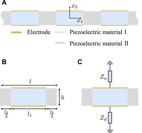
FIGURE 1. (A) Schematic of the periodic piezoelectric plate covered by periodic electrodes on both sides, (B) its corresponding unit cell, and (C) the considering electrical boundary conditions.
Due to the spatial periodicity of piezoelectric plate, the material parameter tensor B can be expanded into Fourier series in the x1 direction as
where
so,
In addition, the density of the periodic plate can be silimlarly expanded into Fourier series as the material parameter tensor. For the spatial periodicity of piezoelectric plate along x1 axis, the Fourier expansion coefficient matrix is the same for all the unit cells.
Here, we only consider the wave propagation along x1 direction, and the plane strain condition is adopted [63] to simplify Eq. 6, i.e., ∂/∂x2 = 0. Therefore, the basic form of generalized displacement vector is
where k1 and k3 are the wave vector components along x1 and x3 axes, respectively, ω is the angular frequency, a is the unknown coefficient vector. The periodicity along x1 indicates that the solution of the generalized displacement vector can be expanded by the form of Fourier series based on the Bloch theorem as
Substituting Eq. 9 into Eq. 8, we obtain the generalized displacement vector in one-dimensional periodic structure as
In order to get the solution of generalized displacement, the main attention is focused on solving the wave vector component k3 and coefficient vectors an.
2.3 The extended Stroh formalism for elastic dynamics
For simplicity, several matrices related to are introduced as
Because the material parameters are functions of x1, then, Eq. 6 is rewritten as
where Y = diag(1, 1, 1, 0). Substituting Eqs 7, 10 into Eq. 12, and set p = m + n, we obtain
where
If the elementary solution is set by
the orthogonality condition can be satisfied, i.e.
where a is an arbitrary real number. In practice, the infinite sums in Eq. 13 are truncated by a finite value N, and only 2N + 1 terms are considered. Taking advantage of the orthogonality relation in Eq. 15, the finite expansion of Eq. 13 can be equivalently expressed into a system of 2N + 1 linear equations, and it is
for any integer q ∈ [−N, N].
The generalized stress on the plane perpendicular to x3 axis is
Substituting Eqs 7, 10 into Eq. 17, and defining
where
It derives
Setting all the 2N + 1 vectors of an as a new column vector
where the matrices of
Because the matrix
From Eqs. 14, 19, the matrix F can be expressed by G as
Combining Eq. 22 and the qth linear equation in Eq. 16, when q takes all the integers from −N to N, the linear system of 2N + 1 equations can be rearranged as
where
Therefore, from Eqs. 21, 23, we obtain the following eigen relation as
where
The solution ξ is called Stroh eigenvector, where
and
where the unknown coefficients cr can be determined by different given boundary conditions on the surfaces of plate.
In order to study the propagations of elastic waves in periodic piezoelectric plate, the electromechanical coupling effect needs to be considered by the mechanical and electrical boundary conditions on the surfaces. The dispersion properties can be changed by various electrical boundary conditions, so that the tunable band structures can be achieved.
The traction free boundary conditions on the surfaces of periodic piezoelectric plate can be expressed by
No matter what kinds of external circuits are shunted via the electrodes whose thickness is negligible, the electrical boundary conditions can be expressed as functions of electric potential ϕ and normal component of electric displacement vector D3 on surfaces, that is
By considering the orthogonality condition in Eqs. 15, a combination of the mechanical and electrical boundary conditions in Eqs. 26, 27 can be conducted by multiplying H(−k1, − q, x1) and integrating them along x1 axis from
where c is a column vector consisting of unknown coefficients cr. In order to get the non-trivial solution, the determinant of coefficient matrix must be equal to zero. Then, the dispersion relation between wave number k1 and angular frequency ω can be obtained by
Therefore, the dispersion relations of periodic piezoelectric plate can be obtained by solving Eq. 29 to explore the characteristics of guided wave motion.
3 Piezoelectric plate with periodic shunting circuit
3.1 Electrical boundary conditions
When the periodic piezoelectric plate is located in a vacuum, the normal components of electric displacement in the vacuum are
The electric potentials in the vacuum are ϕ± and satisfy the Laplace equation, i.e. ▽2ϕ± = 0. Because the electric potentials gradually decrease in the vacuum and vanish at infinite, they can be expressed as
where
From Eq. 24, the electric potential in the plate is
where
where ϵ0 = 8.854 × 10⁻¹² F/m is the dielectric constant in the vacuum.
Using Eq. 25, the normal component of electric displacement of the plate can be expressed as
where
where
where the electric potential
In addition, the charge densities on surfaces are
where
Therefore the electric potential
Correspondingly, the influences of electrical boundary conditions on dispersion relations of periodic piezoelectric plate can be analyzed to investigate the manipulating mechanism.
3.2 Loaded with shunting circuit
3.2.1 Electrically open circuit
When the Jth unit cell is electrically isolated, each electrode is recognized as an equipotential body and satisfies the condition of charge conservation to make the total charge of Eq. 37 equal to zero, so that the electric potentials
Substituting Eq. 39 into Eq. 38, the electrical boundary conditions of electrically open circuit on both surfaces can be expressed by
3.2.2 Electrically short circuit
If the electrodes of the Jth unit cell are connected to the ground, their electrical potentials are forced to zero, that is
3.2.3 Loaded external circuit
If the impedances on the upper and lower electrodes of the Jth unit cell are Zu, Zd, separately, as shown in Figure 1C, the charges on the electrodes of the Jth unit cell can be derived as
Combining Eqs. 42, 37, the electric potentials on the electrodes of the Jth unit cell can be expressed as
Substituting Eq. 43 into Eq. 38, it leads to
Obviously, when the impedances Zu or Zd → ∞, the circuit becomes electrically open case, and Eq. 44 can be degenerated to Eq. 40. When the impedances Zu or Zd = 0, the circuit can also be equivalently transformed into electrically short case with Eq. 44 degenerated to Eq. 41. Otherwise, for different values of impedances Zu or Zd, there are various electrical boundary conditions to be provided.
The different kinds of electrical boundary conditions are converted into a set of linear homogeneous equations. Combining the wave motion equation in Eq. 6 and boundary conditions in Eqs. 26, 27, the eigenvalues and eigenvectors in Eqs. 28, 29 can be determined, and the generalized solutions Eqs. 24, 25 can be obtained in an accurate form with infinite N or an approximate form with the truncating finite terms of N.
4 Electromechanical coupling effects on guided waves
In order to discuss the electromechanical coupling effects on the guided wave propagation in the periodic structure, a periodic piezoelectric plate made of PZT-5H is considered and the material parameters based on its three material principal axes are listed in Table 1 with the Voigt notation. Each unit cell of the periodic piezoelectric plate is constructed by two PZT segments with separately polarized directions and shunted external circuits. Based on the theoretical model, the dispersion curves of both Lamb waves and SH waves in the periodic piezoelectric plate can be calculated under different electrical boundary conditions. By changing the polarization directions of PZT segments in a unit cell or shunting different types of external circuits, the dispersion properties of periodic piezoelectric plates can be easily altered to control the performances of guided waves propagations.
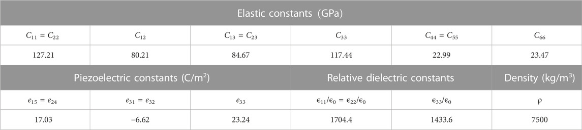
TABLE 1. Material parameters of PZT-5H [31].
If the sizes of unit cell in Figure 1B are set l = 5 mm, h = 3 mm the dimensionless wave number k1l and dimensionless frequency
4.1 Polarized along the x2 axis
If the unit cell in Figure 1B is designed by a combination of part I with l1 = 0.8 L and part II with l2 = 0.2 L, both parts are made of PZT-5H with the polarization directions along x2 axis as illustrated in Figure 2 with red crosses, and only the surfaces of part I are fully covered with thin electrodes. It means that there is no difference between the piezoelectric materials in part I and part II except part I can connect external circuits. For discussing the influences of external circuits on the dispersion properties of the periodic piezoelectric plate, the shunting inductance circuit is considered. Compared to the electrically open case in Figure 2A, the external inductance circuit is set by connecting inductance L on the upper electrode, and the lower electrode is connected to the ground as shown in Figure 2B, i.e. Zu = iωL, Zd = 0. If the inductor in Figure 2B is chosen by L = 50 μH and L = 30 μH, separately, the corresponding dispersion curves of Figures 2A,B can be calculated by Eq. 29 and results are shown in Figure 3. For the case without external circuits in Figure 2A, the dispersion curves of Lamb waves and SH wave are the same as homogeneous plate as shown in Figure 3A, and the corresponding finite element results are obtained by the commercial software COMSOL Multiphysics and illustrated by gray rhombus marks. In Figure 3A, these two results are in complete agreement, so that the effectiveness and reliability of Eq. 29 is verified.
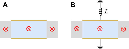
FIGURE 2. The periodic unit cell made of x2 direction polarized PZT with different electrical boundary conditions: (A) electrically open, (B) shunting inductance.
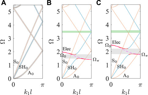
FIGURE 3. Dispersion curves of periodic plates with unit cells of (A) Figure 2A, (B) Figure 2B with L = 50 μH and (C) Figure 2B with L = 30 μH.
If the external circuits are involved, the dispersion curves of Lamb waves and SH wave are also calculated by Eq. 29 and shown in Figures 3B,C, and there is an extra electric mode (red lines) to couple with the guided waves compared to Figure 3A. The corresponding finite element results calculated by COMMOL Multiphysics are not presented here because the “Electrical Circuit” interface of COMSOL is unstably supported for eigenvalue problem. Therefore, the reliability of Eq. 29 when the shunting circuits are involved is verified by the dispersion relation of the electric mode before coupling with guided waves, which can be derived from the equivalent-circuit model [44] as
and illustrated by rose dashed curves in Figures 3B,C.
In this model, the unit cell in Figure 2B can be equivalent represented by a capacitor CI whose surfaces are perpendicular to x3 axis, and form a inductance-capacitance resonant circuit with the shunting inductance. In addition, the electrodes on the upper surfaces of adjacent unit cells are connected by an equivalent capacitor CII whose surfaces are perpendicular to x1 due to the electrical potential differences on these two electrodes. The values of CI and CII can be determined by the cutoff frequency ω0 and ωπ denoted as the dimensionless Ω0 and Ωπ in Figures 3B,C at the edges of Brillouin zone k1l = 0 and k1l → π.
In Figures 3B,C, the shunted inductance circuit has no effect on Lamb waves due to their displacement vectors are perpendicular to the polarization orientation of piezoelectric material. By contrast, there is a strong interaction between the electric mode and SH0 wave for the same directions of displacement vector and polarization orientation, and opening up the hybridization bandgaps as shown by gray shadow areas. According to Eq. 45, the lower inductance L can induce the electric mode at higher frequency range, and can result in the hybridization bandgaps at higher frequency range too, as shown in Figures 3B,C. The width of the hybridization bandgap increases to 1.3 times when the inductances decrease from 50 μH to 30 μH. Compared to Figure 3A, besides the hybridization bandgaps caused by electric mode, there is an extra narrow Bragg scattering bandgap (green shadow region) to be generated in Figures 3B,C for the periodicity of piezoelectric plate.
4.2 Polarized along the x3 axis
The design of unit cell in Figure 4 is the same as that in Figure 2, except the polarization directions are all along x3 axis as shown in Figure 4 with red arrows, and for Figure 4B the same electrical boundary conditions are considered as described in Section 4.1. The corresponding dispersion curves are calculated by Eq. 29 and results are illustrated in Figure 5. For the case of electrically open in Figure 4A, the finite element results are provided by the commercial software COMSOL Multiphysics and plotted in Figure 5A by gray rhombus symbols to show the good consistence with the theoretical model.
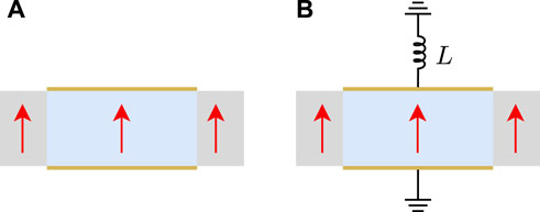
FIGURE 4. The periodic unit cell made of x3 direction polarized PZT with different electrical boundary conditions: (A) electrically open, (B) shunting inductance.
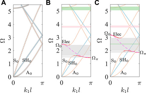
FIGURE 5. Dispersion curves of periodic plates with unit cells of (A) Figure 4A, (B) Figure 4B with L = 50 μH and (C) Figure 4B with L = 30 μH.
Compared to the dispersion curves in Figure 3, the big difference is that the shunting inductance circuit of Figure 4B has no influence on SH wave and the hybridization bandgaps emerge only from the coupling of the electric mode with the Lamb waves as gray shadow regions in Figures 5B,C. In Figures 5B,C, there is a stronger interaction with S0-like mode to form a broader hybridization bandgap than that with A0-like mode. It indicates that the electromechanical coupling effect on the guided waves can be effectively selected by the polarization direction of piezoelectric material. For the same shunting inductor with L = 50 μH, the electric mode calculated by Eq. 45 can cover a wider frequency range with lower Ωπ and higher Ω0 in Figure 5B than that in Figure 3B, and leads to a nearly three times wider hybridization bandgap of S0-like mode than that of SH0 mode in Figure 3B. Similarly, the difference of the dispersion relations between Figure 5C and Figure 3C can be observed when the shunting inductor is L = 30 μH. Besides, there is another hybridization bandgap by the interaction between S0-like mode and the folded negative-slope A0-like mode denoted as the pink shadow regions in Figures 5B,C. The Bragg scattering bandgaps emerge when A0-like and S0-like waves are folded at the edge of the Brillouin zone, as denoted the green shadow areas in Figures 5B,C, and they are only related to the periodicity of piezoelectric plate but little influence by the shunting inductance circuit.
4.3 Polarized along the x1 axis in part I and x3 axis in part II
If two parts of unit cell are designed by the same PZT with different polarization directions, which are along x1 axis in part I and x3 axis in part II as illustrated in Figure 6, the dispersion curves of guided waves under the electrical boundary conditions of electrically open, shunting inductance with L = 50 μH and L = 30 μH, separately, can be calculated by Eq. 29 and shown in Figure 7. The differences of electromechanical coupling effects caused by the polarization directions and the shunting inductance circuits can be figured out in the dispersion curves of guided waves in Figure 7.
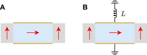
FIGURE 6. The periodic unit cell made of x1 direction and x3 direction polarized PZT with different electrical boundary conditions: (A) electrically open, (B) shunting inductance.
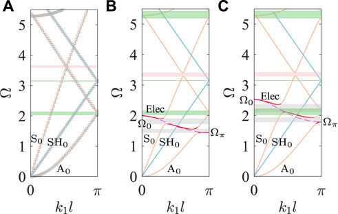
FIGURE 7. Dispersion curves of periodic plates with unit cells of (A) Figure 6A, (B) Figure 6B with L = 50 μH and (C) Figure 6B with L = 30 μH.
Similar to the dispersion curves in Figure 5, the external circuits have no influence on the propagation of SH waves in Figure 7, because the unit cell has no PZT part with the polarization direction along x2 axis, i.e. the direction of SH wave motion, and the hybridization bandgaps shaded in gray in Figures 7B,C are only generated by the coupling of electric mode with A0-like and S0-like modes. However, there are some differences to be observed between Figures 5, 7. First, the Bragg bandgaps appear in Figure 7 when the guided waves fold at the edges of Brillouin zones for the periodicity of plate, but Bragg bandgaps of SH0 branch cannot be observed in Figure 5 for the homogeneity of plate. In Figure 7, the bandgap of SH0 branch is very narrow, and the bandgaps of A0-like branch in Figures 7B,C are wider than that in Figures 5B,C while the bandgaps of S0-like branch are thinner. Second, because the normal component of the dielectric tensor of PZT-5H after coordinate transformation increases when the polarization direction changes from x3 to x1 axis, and correspondingly the equivalent capacitance CI increases, in consequence, the corresponding electric modes can cover a narrower frequency range in Figures 7B,C than that in Figures 5B,C. This is because the upper limits of electric modes decrease for the higher CI based on Eq. 45, while the lower limits almost remain the same, so that the hybridization bandgaps open up at lower frequencies. Furthermore, the hybridization bandgaps are also influenced by the polarization directions, especially when the electric mode couples with S0-like mode, the hybridization bandgaps in Figures 7B,C are narrower to be about 20% of that in Figures 5B,C.
4.4 Polarized along the x2 axis in part I and x3 axis in part II
The two parts of unit cell are designed in series with the same length l1 = l2 = 0.5 l, and the electrodes are centered on both surfaces of these two parts with the length of a1 = 0.8 l1, a2 = 0.8 l2, respectively. The polarization directions of PZT are along x2 axis in part I and x3 axis in part II, as illustrated in Figure 8 with red crosses and arrows. The unit cell in Figure 8 is a combination of that in Figures 2, 4 with a half length. There are three different electrical boundary conditions to be considered as shown in Figure 8, the electrically open condition in Figure 8A, inductance shunting circuit loaded on the upper electrodes of part I in Figure 8B or part II in Figure 8C with the opposite lower electrodes connected to the ground. The dispersion curves of these three cases are calculated and shown in Figure 9, and the finite element results are obtained and drawn with gray rhombus marks to illustrate the good consistence in Figure 9A.
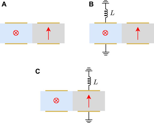
FIGURE 8. The periodic unit cell made of x2 direction and x3 direction polarized PZT with different electrical boundary conditions: (A) electrically open, (B) inductance shunting on part I and (C) inductance shunting on part II.
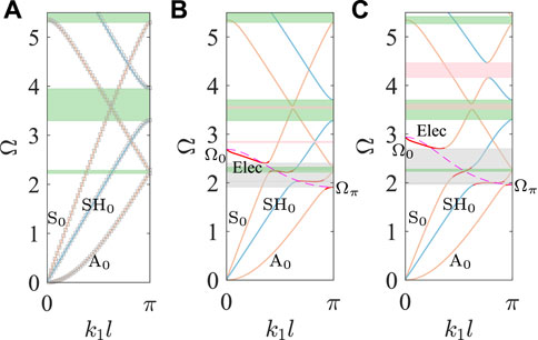
FIGURE 9. Dispersion curves of periodic plates with unit cells of (A) Figure 8A, (B) Figure 8B with L = 50 μH and (C) Figure 8C with L = 50 μH.
The big difference between Figure 7A and Figure 9A is the much wider Bragg bandgap (shaded in green) of SH0 wave in Figure 9A for the part I polarized along the direction of SH0 wave, and the broader length of part II polarized along axis in Figure 9A than the part II with the same polarization direction in Figure 7A cause a lower Bragg bandgap of S0-like mode and a higher Bragg bandgap of A0-like mode. Compared to Figure 3B with the same polarized PZT part shunted inductance circuit, the electric mode is located at a higher frequency range as rose dashed line in Figure 9B, and the electromechanical effect not only induces the hybridization bandgap (shaded in gray) of SH0 mode, but also causes the hybridization bandgaps for both A0-like and S0-like modes. The similar conclusion can be addressed from the comparison of Figure 5B and Figure 9C for the same polarized PZT part shunted inductance circuit, but the frequency range of electric mode is narrower in Figure 9C. It indicates that the hybridization bandgap caused by electromechanical effect strongly depends on the polarization direction of PZT, but the external circuit can influence the frequency range of electric mode. For a comparison of three Bragg bandgaps in Figure 9, the shunting inductance circuit can strongly decrease the frequency range of SH0 mode no matter which part is shunted, but only slightly influences on both A0-like and S0-like modes. However, if the shunting inductance circuit is connected to the upper electrode of part I as shown in Figure 9B, the interactions between different wave modes are slight and hard to observe, while for the shunting inductance circuit connected to the upper electrode of part II as shown in Figure 9C, the S0-like mode is strongly interacted with the folded negative-slope SH0 mode and A0-like mode to result in the opening up locally resonant bandgaps shaded in pink.
From Figures 3, 5, 7, 9, it is noteworthy that the obvious Bragg bandgaps can be observed for the heterogeneous plate with periodicity, and the heterogeneity can be induced by locally shunting circuits for homogeneous plate or by different polarization directions of two PZT segments. The external inductance circuits can introduce the electric mode to form the hybridization bandgaps after its interaction with guided waves. In addition, the coupling effect of electric mode only acts on the specific mode guided waves that have non-zero motion component along the polarization direction of PZT. It should be noticed in Figures 9B,C that the hybridization bandgap depends on the polarization direction of PZT even though the external circuit is connected to other PZT segments with different polarization directions.
5 Conslusion
Based on the extended Stroh formalism, a theoretical model is proposed for solving the guided wave propagation in periodic piezoelectric plate, and the dispersion relations of multi-modes guided waves in the periodic piezoelectric plate shunted with external circuits are theoretically investigated in this paper. Based on the theoretical analysis, the dispersion properties of the periodic piezoelectric plate can be manipulated by altering the polarization direction of piezoelectric material in a unit cell and the impedance parameters of shunting circuit, and the main points can be addressed as follows.
1. The periodic piezoelectric structure behaves as a combination of phononic crystal plate and metamaterial with shunting circuits. Consequently, both the Bragg bandgaps and the hybridization bandgaps emerge in different frequency ranges due to the electromechanical coupling effects. Compared to the Bragg bandgaps, the hybridization bandgaps locate at lower frequencies, hence, the manipulation of wave propagation can be achieved at subwavelength scale.
2. The shunting circuits connected to homogeneous unit cell can induce obvious bandgaps of guided wave when its motion direction is not perpendicular to the polarization direction of piezoelectric material. For the unit cell composed of piezoelectric materials with different polarization directions, the Bragg bandgap will appear no matter whether the shunting circuits exist or not.
3. The hybridization bandgaps originate from the coupling between electric mode and guided wave modes whose motion direction is the same as the polarization direction of the piezoelectric material in a unit cell. Hence, the manipulation of specific wave propagation can be achieved via the requested arrangement of polarization directions in a unit cell with shunting circuits.
4. The frequency range of the electric mode in the dispersion curves is modulated with the various inductance values and polarization orientations of the piezoelectric material in a unit cell, leading to the hybridization bandgaps opening at variable frequencies. Therefore, a tunable band structure of the periodic piezoelectric plate can be realized with the help of various electrical boundary conditions and different polarization orientation permutations of the segments in a unit cell.
In summary, the proposed theoretical model in this paper can be successfully applied to the wave motion problem of periodic piezoelectric plate with shunting circuits. Results predict that the periodic plate has a good ability to manipulate guided wave propagation and provide broad applications in wave guiding and controlling, non-destructive testing, and other engineering fields. Furthermore, the theoretical model can be developed to investigate the dispersion characters of guided waves in the periodic plate made of various materials with more multi-physics properties, such as piezomagnetic effect, and plate with more complex structures, such as multiple-layers, can also be studied by the modification of the theoretical approach.
Data availability statement
The original contributions presented in the study are included in the article/Supplementary Material, further inquiries can be directed to the corresponding author.
Author contributions
YZ: Conceptualization, methodology, software and data analysis, writing-original draft; RX: Conceptualization, validation, data analysis, reviewing and editing; KH: Supervision, reviewing; ZL: Supervision, writing-review and editing, funding acquisition. All authors listed have made a substantial contribution to the proposed work and approved the submitted version.
Funding
This work was supported by the National Natural Science Foundation of China under Grants No. 12172008 and No. 11991033.
Conflict of interest
The authors declare that the research was conducted in the absence of any commercial or financial relationships that could be construed as a potential conflict of interest.
Publisher’s note
All claims expressed in this article are solely those of the authors and do not necessarily represent those of their affiliated organizations, or those of the publisher, the editors and the reviewers. Any product that may be evaluated in this article, or claim that may be made by its manufacturer, is not guaranteed or endorsed by the publisher.
References
1. Ji G, Huber J. Recent progress in acoustic metamaterials and active piezoelectric acoustic metamaterials - a review. Appl Mater Today (2021) 26:101260. doi:10.1016/j.apmt.2021.101260
2. Vasileiadis T, Varghese J, Babacic V, Gomis-Bresco J, Navarro Urrios D, Graczykowski B. Progress and perspectives on phononic crystals. J Appl Phys (2021) 129:160901. doi:10.1063/5.0042337
3. Xia R, Nassar H, Chen H, Li Z, Huang G. Microtwist homogenization of three-dimensional Pyrochlore lattices on zero modes and mechanical polarization. J Mech Phys Sol (2021) 155:104564. doi:10.1016/j.jmps.2021.104564
4. Chen H, Wang S, Li X, Huang G. Two-dimensional microtwist modeling of topological polarization in hinged Kagome lattices and its experimental validation. Int J Sol Structures (2022) 254-255:111891. doi:10.1016/j.ijsolstr.2022.111891
5. Yi J, Li Z, Negahban M, Xia R, Zhu J. Asymmetric viscoelastic metamaterials for broad bandgap design and unidirectional zero reflection. Mech Syst Signal Process (2022) 162:108101. doi:10.1016/j.ymssp.2021.108101
6. Valipour A, Kargozarfard MH, Rakhshi M, Yaghootian A, Sedighi HM. Metamaterials and their applications: An overview. Proc Inst Mech Eng L: J Mater Des Appl (2021) 236:2171–210. doi:10.1177/1464420721995858
7. Chiou MJ, Lin YC, Ono T, Esashi M, Yeh SL, Wu TT. Focusing and waveguiding of Lamb waves in micro-fabricated piezoelectric phononic plates. Ultrasonics (2014) 54:1984–90. doi:10.1016/j.ultras.2014.05.007
8. Wang Y, Zhao W, Rimoli JJ, Zhu R, Hu G. Prestress-controlled asymmetric wave propagation and reciprocity-breaking in tensegrity metastructure. Extreme Mech Lett (2020) 37:100724. doi:10.1016/j.eml.2020.100724
9. Miniaci M, Gliozzi A, Morvan B, Krushynska A, Bosia F, Scalerandi M, et al. Proof of concept for an ultrasensitive technique to detect and localize sources of elastic nonlinearity using phononic crystals. Phys Rev Lett (2017) 118:214301. doi:10.1103/PhysRevLett.118.214301
10. Yi J, Negahban M, Li Z, Su X, Xia R. Conditionally extraordinary transmission in periodic parity-time symmetric phononic crystals. Int J Mech Sci (2019) 163:105134. doi:10.1016/j.ijmecsci.2019.105134
11. Wu Q, Zhang X, Shivashankar P, Chen Y, Huang G. Independent flexural wave frequency conversion by a linear active metalayer. Phys Rev Lett (2022) 128:244301. doi:10.1103/PhysRevLett.128.244301
12. Cui R, Zhou J, Gong D. Wave-resistance sleeper with locally resonant phononic crystals: Bandgap property and vibration reduction mechanism. AIP Adv (2021) 11:035043. doi:10.1063/5.0027591
13. Zhang B, Chen P, Chen H, Feng T, Cai C, Zhang J. Application of phononic crystals for vibration reduction and noise reduction of wheel-driven electric buses based on neural networks. Proc Inst Mech Eng D: J Automobile Eng (2022) 236:1619–27. doi:10.1177/09544070211035906
14. Liu L, Lee HP. A review: Elastic metamaterials and inverse design methods for shock and vibration mitigation. Int J Appl Mech (2021) 13:2150102. doi:10.1142/S1758825121501027
15. Arretche I, Matlack KH. Locally resonant effective phononic crystals for subwavelength vibration control of torsional cylindrical waves. J Vib Acoust (2021) 144:031007. doi:10.1115/1.4052748
16. Dalela S, Balaji PS, Jena DP. A review on application of mechanical metamaterials for vibration control. Mech Adv Mater Structures (2022) 29:3237–62. doi:10.1080/15376494.2021.1892244
17. Arretche I, Matlack K. Effective phononic crystals for non-Cartesian elastic wave propagation. Phys Rev B (2020) 102:134308. doi:10.1103/PhysRevB.102.134308
18. Kushwaha M, Djafari-Rouhani B, Dobrzynski L. Sound isolation from cubic arrays of air bubbles in water. Phys Lett A (1998) 248:252–6. doi:10.1016/S0375-9601(98)00640-9
19. Tamura S, Hurley DC, Wolfe JP. Acoustic-phonon propagation in superlattices. Phys Rev B (1988) 38:1427–49. doi:10.1103/PhysRevB.38.1427
20. Oudich M, Gerard NJ, Deng Y, Jing Y. Tailoring structure-borne sound through bandgap engineering in phononic crystals and metamaterials: A comprehensive review. Adv Funct Mater (2022) 2022:2206309. doi:10.1002/adfm.202206309
21. Wu Q, Chen H, Nassar H, Huang G. Non-reciprocal Rayleigh wave propagation in space–time modulated surface. J Mech Phys Sol (2021) 146:104196. doi:10.1016/j.jmps.2020.104196
22. Wang YF, Wang YZ, Wu B, Chen W, Wang YS. Tunable and active phononic crystals and metamaterials. Appl Mech Rev (2020) 72:040801. doi:10.1115/1.4046222
23. Guo X, Wei P, Lan M, Li L. Dispersion relations of elastic waves in one-dimensional piezoelectric/piezomagnetic phononic crystal with functionally graded interlayers. Ultrasonics (2016) 70:158–71. doi:10.1016/j.ultras.2016.04.025
24. Guo X, Wei P, Li L. Dispersion relations of elastic waves in one-dimensional piezoelectric phononic crystal with mechanically and dielectrically imperfect interfaces. Mech Mater (2016) 93:168–83. doi:10.1016/j.mechmat.2015.11.004
25. Guo X, Wei P. Dispersion relations of elastic waves in one-dimensional piezoelectric phononic crystal with initial stresses. Int J Mech Sci (2016) 106:231–44. doi:10.1016/j.ijmecsci.2015.12.020
26. Yan DJ, Chen AL, Wang YS, Zhang C, Golub M. In-plane elastic wave propagation in nanoscale periodic layered piezoelectric structures. Int J Mech Sci (2018) 142–143:276–88. doi:10.1016/j.ijmecsci.2018.04.054
27. Yan DJ, Chen AL, Wang YS, Zhang C, Golub M. Propagation of guided elastic waves in nanoscale layered periodic piezoelectric composites. Eur J Mech - A/Solids (2017) 66:158–67. doi:10.1016/j.euromechsol.2017.07.003
28. Chen AL, Yan DJ, Wang YS, Zhang C. In-plane elastic wave propagation in nanoscale periodic piezoelectric/piezomagnetic laminates. Int J Mech Sci (2019) 153–154:416–29. doi:10.1016/j.ijmecsci.2019.02.017
29. Vasseur C, Croënne C, Vasseur JO, Dubus B, Thi MP, Prévot C, et al. Electrical evidence of the tunable electrical Bragg bandgaps in piezoelectric plates. IEEE Trans Ultrason Ferroelectr Freq Control (2018) 65:1552–62. doi:10.1109/TUFFC.2018.2847246
30. Kherraz N, Haumesser L, Levassort F, Benard P, Morvan B. Controlling Bragg gaps induced by electric boundary conditions in phononic piezoelectric plates. Appl Phys Lett (2016) 108:093503. doi:10.1063/1.4943138
31. Xia R, Zhu J, Yi J, Shao S, Li Z. Guided wave propagation in multilayered periodic piezoelectric plate with a mirror plane. Int J Mech Sci (2021) 204:106539. doi:10.1016/j.ijmecsci.2021.106539
32. Forward RL. Electronic damping of vibrations in optical structures. Appl Opt (1979) 18:690–7. doi:10.1364/AO.18.000690
33. Gripp JAB, Rade DA. Vibration and noise control using shunted piezoelectric transducers: A review. Mech Syst Signal Process (2018) 112:359–83. doi:10.1016/j.ymssp.2018.04.041
34. Wu Q, Chen Y, Huang G. Asymmetric scattering of flexural waves in a parity-time symmetric metamaterial beam. The J Acoust Soc America (2019) 146:850–62. doi:10.1121/1.5116561
35. Flores Parra E, Bergamini A, Van Damme B, Ermanni P. Controllable wave propagation of hybrid dispersive media with LC high-pass and band-pass networks. Appl Phys Lett (2017) 110:184103. doi:10.1063/1.4983088
36. Yi J, Ma Z, Xia R, Negahban M, Chen C, Li Z. Structural periodicity dependent scattering behavior in parity-time symmetric elastic metamaterials. Phys Rev B (2022) 106:014303. doi:10.1103/PhysRevB.106.014303
37. Chen Y, Hu G, Huang G. An adaptive metamaterial beam with hybrid shunting circuits for extremely broadband control of flexural waves. Smart Mater Struct (2016) 25:105036. doi:10.1088/0964-1726/25/10/105036
38. Li X, Chen Y, Hu GK, Huang G. A self-adaptive metamaterial beam with digitally controlled resonators for subwavelength broadband flexural wave attenuation. Smart Mater Struct (2018) 27:045015. doi:10.1088/1361-665X/aab167
39. Sugino C, Ruzzene M, Erturk A. Merging mechanical and electromechanical bandgaps in locally resonant metamaterials and metastructures. J Mech Phys Sol (2018) 116:323–33. doi:10.1016/j.jmps.2018.04.005
40. Xia R, Shao S, Yi J, Zheng K, Negahban M, Li Z. Tunable asymmetric transmission of Lamb waves in piezoelectric bimorph plates by electric boundary design. Compos Structures (2022) 300:116111. doi:10.1016/j.compstruct.2022.116111
41. Shao S, Xia R, Li Z. Tunable piezoelectric metasurface for manipulating multi-mode guided waves in plate. Eng Structures (2022) 270:114917. doi:10.1016/j.engstruct.2022.114917
42. Xia R, Yi J, Chen Z, Li Z. In situ steering of shear horizontal waves in a plate by a tunable electromechanical resonant elastic metasurface. J Phys D Appl Phys (2020) 53:095302. doi:10.1088/1361-6463/ab5cbc
43. Wang Y, Zhang C, Chen W, Li Z, Golub MV, Fomenko SI. Precise and target-oriented control of the low-frequency Lamb wave bandgaps. J Sound Vibration (2021) 511:116367. doi:10.1016/j.jsv.2021.116367
44. Kherraz N, Haumesser L, Levassort F, Benard P, Morvan B. Hybridization bandgap induced by an electrical resonance in piezoelectric metamaterial plates. J Appl Phys (2018) 123:094901. doi:10.1063/1.5016496
45. Chikh-Bled FH, Kherraz N, Sainidou R, Rembert P, Morvan B. Piezoelectric phononic plates: Retrieving the frequency band structure via all-electric experiments. Smart Mater Struct (2019) 28:115046. doi:10.1088/1361-665X/ab4aac
46. Kherraz N, Chikh-Bled FH, Sainidou R, Morvan B, Rembert P. Tunable phononic structures using Lamb waves in a piezoceramic plate. Phys Rev B (2019) 99:094302. doi:10.1103/PhysRevB.99.094302
47. Stroh AN. Dislocations and cracks in anisotropic elasticity. Philos Mag (1958) 3:625–46. doi:10.1080/14786435808565804
48. Stroh AN. Steady state problems in anisotropic elasticity. J Maths Phys (1962) 41:77–103. doi:10.1002/sapm196241177
49. Ting TTC. Anisotropic elasticity: Theory and applications. Oxford, UK: Oxford University Press (1996). doi:10.1093/oso/9780195074475.001.0001
50. Tanuma K. Stroh formalism and Rayleigh waves. J Elast (2007) 89:5–154. doi:10.1007/s10659-007-9117-1
51. Hsu CL, Hwu C, Shiah YC. Three-dimensional boundary element analysis for anisotropic elastic solids and its extension to piezoelectric and magnetoelectroelastic solids. Eng Anal Boundary Elem (2019) 98:265–80. doi:10.1016/j.enganabound.2018.10.022
52. Kuo HY, Shih CL, Pan E. Enhancing magnetoelectric effect in magneto-electro-elastic laminated composites via interface modulus and stress. Int J Sol Structures (2020) 195:66–73. doi:10.1016/j.ijsolstr.2020.03.014
53. Hsu CW, Hwu C. Holes/cracks/inclusions in magneto-electro-elastic composite laminates under coupled stretching-bending deformation. Compos Structures (2022) 297:115960. doi:10.1016/j.compstruct.2022.115960
54. Tassi N, Magouh N, Azrar L. 3D static analysis of homogenized piezoelectric plates based on the Mori-Tanaka and the Stroh approach. In: 2020 IEEE 7th International Conference on Engineering Technologies and Applied Sciences (ICETAS). Kuala Lumpur, Malaysia: IEEE (2020). p. 1–6. doi:10.1109/ICETAS51660.2020.9484313
55. Manyo Manyo JA, Ntamack GE, Azrar L. 3D-dynamic modeling of cross-ply magneto-electro-elastic laminates based on the pseudo-Stroh formalism. Mech Adv Mater Structures (2021) 28:1337–54. doi:10.1080/15376494.2019.1668094
56. Manyo Manyo JA, Ntamack GE, Azrar L. Time and frequency 3D-dynamic analyses of multilayered magnetoelectroelastic plates with imperfect interfaces. Arch Appl Mech (2022) 92:2273–301. doi:10.1007/s00419-022-02177-3
57. Magouh N, Lahcen A. Mathematical modeling of linear dynamic response of piezoelectric single Pz52 plates based on Stroh-like Formalism. In: 2021 7th International Conference on Optimization and Applications (ICOA). Wolfenbüttel, Germany: IEEE (2021). p. 1–6. doi:10.1109/ICOA51614.2021.9442670
58. Ewolo Ngak FP, Ntamack GE, Azrar L. Dynamic analysis of multilayered magnetoelectroelastic plates based on a pseudo-Stroh formalism and Lagrange polynomials. J Intell Mater Syst Structures (2019) 30:939–62. doi:10.1177/1045389X19828505
59. Tian R, Liu J, Pan E, Wang Y. SH waves in multilayered piezoelectric semiconductor plates with imperfect interfaces. Eur J Mech - A/Solids (2020) 81:103961. doi:10.1016/j.euromechsol.2020.103961
60. Huang H, Zhu F, Zhu J, Wang B, Qian Z. A general approach for dispersion relations in multilayered structures with an arbitrary number of piezoelectric layers and elastic layers. Acta Mech (2020) 231:489–502. doi:10.1007/s00707-019-02540-6
61. Kuo HY, Wang YH. Wave motion of magneto-electro-elastic laminated plates with membrane-type interfacial imperfections. Compos Structures (2022) 293:115661. doi:10.1016/j.compstruct.2022.115661
62. Tian R, Liu J, Pan E, Wang Y, Soh AK. Some characteristics of elastic waves in a piezoelectric semiconductor plate. J Appl Phys (2019) 126:125701. doi:10.1063/1.5116662
Keywords: metamaterials, phononic crystals, guided waves, piezoelectricity, electromechanical coupling, Stroh formalism
Citation: Zhang Y, Xia R, Huang K and Li Z (2022) Theoretical analysis of guided waves propagation in periodic piezoelectric plates with shunting circuits. Front. Phys. 10:1094077. doi: 10.3389/fphy.2022.1094077
Received: 09 November 2022; Accepted: 05 December 2022;
Published: 22 December 2022.
Edited by:
Xiaopeng Li, Toyota Research Institute of North America, United StatesReviewed by:
Qian Wu, University of Missouri, United StatesMenglong Liu, Harbin Institute of Technology, Shenzhen, China
Copyright © 2022 Zhang, Xia, Huang and Li. This is an open-access article distributed under the terms of the Creative Commons Attribution License (CC BY). The use, distribution or reproduction in other forums is permitted, provided the original author(s) and the copyright owner(s) are credited and that the original publication in this journal is cited, in accordance with accepted academic practice. No use, distribution or reproduction is permitted which does not comply with these terms.
*Correspondence: Zheng Li, bGl6aGVuZ0Bwa3UuZWR1LmNu