Abstract
Introduction: A spin exchange relaxation free atomic magnetometer, as an ultra-highly sensitive magnetic field sensor, is limited by the performance of the probe laser system. The probe laser pumping effect (PLPE) hinders the increase in the performance of probe laser system.
Methods: This study investigated the PLPE and proposed a method for suppressing the same. Through changes to the angle of a quarter wave plate and the addition of a triangular modulated magnetic field to the alkali atoms, the suppression point was determined.
Results and discussion: Further, related parameters were measured for different degree of polarizations of the probe laser, which confirmed that the influence of PLPE on the magnetic field was the least at the suppressed point.
1 Introduction
A spin exchange relaxation free (SERF) atomic magnetometer is a type of sophisticated magnetic field sensor employed in precise quantum measurement regions. It has been widely studied since it was first proposed [1, 2]. There exists considerable potential in basic physical research [3–5] and ultra-high sensitive magnetic field detection [6–8] related to SERF magnetometers. As a type of multi-system ultra-high sensitivity sensor, the noise level of an information detection system in a SERF atomic magnetometer limits its serviceability [9, 10]. Thus, the study of the detection system is a significant research topic.
In SERF atomic magnetometers, a circularly polarized laser is used to pump the alkali metal atoms in a glass cell and the alkali metal atoms are sensitive to the magnetic field at this pumping state [11, 12]. Furthermore, a linearly polarized probe laser is utilized to detect the magnetic field signal based on the optical rotation effect [13]. Linear polarization devices are used to produce the linearly polarized laser in a SERF Atomic magnetometer [14]. However, the final linearly polarized laser is not perfectly linear, which requires the alkali metal atoms to be partly pumped via a probe laser [15, 16]. This phenomenon is referred to as the probe laser pumping effect (PLPE), which is not conducive to SERF atomic magnetometer operation. Thus, this effect must be suppressed and the basic parameters of the SERF atomic magnetometer affected by this effect must be analyzed.
Previous studies attempted to suppress PLPE using a Glan-Taylor prism (extinction ratio of 1000000:1), which is a common type of polarizer used to produce a linear polarized laser with a high degree of linear polarization. Depolarization occurs during the performance of a polarizer, and the effect of other optics and the dispersion of alkali metal atoms in the glass cell are the influencing factors [17]. To avoid the increase in PLPE due to depolarization, an extra quarter wave plate (QWP) is applied to compensate for the degree of linear polarization. Following the compensation from the QWP, the response of alkali metal atoms to the triangular modulated magnetic field is maintained, rather than forming a crest or trough [18]. However, when the degree of polarization (DOP) of the probe laser has been measured, a shift from complete linear polarization has been observed [16]. The optical power density and wavelength of the probe laser can be adjusted to suppress the probe laser pumping effect again [19, 20]. However, all previous studies have only focused on methods to suppress the PLPE; studies on the changes in the main parameters (such as the compensation point Bc) under different suppressed levels are scarce.
In this manuscript, we study the atomic magnetometer in a hybrid atomic ensemble of K-Rb atoms and 21Ne atoms. This study clarified the principle of compensation process of PLPE by QWP. In addition, different degrees of linear polarization were achieved by rotating the QWP in an electric control mirror frame. Simultaneously, the main parameters in the SERF atomic magnetometer were measured and analyzed.
2 Analysis of probe laser pumping phenomenon
The alkali metal gas cell is the sensitive element present in the SERF atomic magnetometer. It contains alkali metal and noble gas atoms that interact with each other. The specific interaction between them can be described based on the Bloch’s equation [14, 21]:where Pe and Pn are the Rb and 21Ne spin polarization vectors, respectively, γe and γn are the gyromagnetic ratios of electrons and nucleus, respectively, the specific values of which are γe = 2π× 28 Hz/nT and γn = 2π×0.00336 Hz/nT, respectively. The nuclear slowing-down factor is expressed as Q(Pe), which is related to the spin polarization vector of electrons. Further, B is the ambient magnetic field that is produced via three-axis magnetic field coils placed in position of the sensitive unit to compensate for the residual magnetic field and the magnetic field from spin atoms along the axial direction. Be and Bn represent the magnetic field produced by the spin of electrons and nucleus, respectively, and represent the spin-destruction relaxation rate of the electron and nuclear, respectively, and , represent the spin-exchange relaxation rate between the electron and nuclear. L is light shift produced from the interaction between light and atoms, which can be regarded as a virtual magnetic field. The PLPE results in a virtual magnetic field along the probe direction , which is considered as the primary source of transverse light shift Lx. To illustrate the Bloch equations in a concise way, all relaxation-related terms are shown in brackets, as in 1 and 2.
A circularly polarized laser is used to pump the alkali metal atoms and a linear polarized laser is used to probe the variations in magnetic field [22]. In an ideal situation, linear polarization does not pump the alkali metal atoms and consequently the light shift Lx does not appear. However, limited by the quality of the polarizer, the formation of a pure linearly polarized light is difficult, which results in a transverse light shift Lx along the probe direction. Consequently, the spin polarization direction is not completely along the pumping direction, which is influenced by the probe laser and shown in Figure 1. This phenomenon is referred to as the PLPE, which must be suppressed.
FIGURE 1
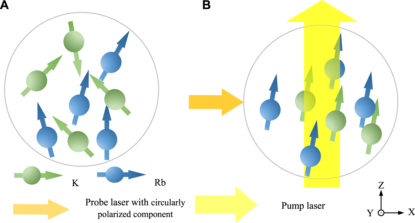
The state of alkali metal atoms (K atoms are represented by green and Rb atoms are represented by blue) in a SERF atomic magnetometer, which are affected by the probe laser pumping effect. (A). The natural state of alkali metal atoms is out of order. (B). Affected by the detection of optical pumping effect, the spin polarization direction is not completely along the pumping direction.
The PLPE will lead the electron spin polarization vector Pe alone the X-axis, which means electrons are pumped along the X-axis. This process can be described using (3) based on the solution of 1 and 2.where is the correlation between the electron spin polarizability vector in X-axis and the magnetic fields along the X and Z-axes, that is Bx and Bz, respectively. Further, is the electron spin polarization vector along the Z-axis and is the total electron relaxation rate. Bc is referred to the compensation point, which is equal to the sum of Be and Bn. In addition, R is a constant in our proposed model, which is used to represent the relaxation correlation.
In this case, is reflected by the collected electrical signal, which is repressed by the S and . In the X-axis, only the transverse light shift Lx exists, which applies a vertical magnetic field. Thus, the magnetic field at the center along X-axis Bx is equal to Lx.
Previous studies have proven that Lx is a comprehensive effect owing to the probe laser and the alkali metal cell [20]. and are defined as the transverse light shift from the laser and cell, respectively. Here, is the classical description of light shift, which is related to the parameters of the laser (such as optical power density and frequency detuning). originates owing to the depolarization of probe laser. Thus, the combined effect of the laser and alkali metal cell Lx is expressed as (5):
Only the is related to the polarization state of the probe laser, which is adjusted in our method. Thus, is shown as (6):where Φ is the photon flux proportional to the probe laser and A is the cross-sectional area of the incident laser. Once the probe laser power is fixed, Φ/A is a constant. Further, re is the radius of classical atoms and f is the oscillator strength of the D1 transition, which are also constants; υ, υ0, and Γ are the frequency of the probe laser, central frequency of alkali metal atoms D1 transition, and frequency at full width at half maximum. Further, sl represents the circularly polarized component; that is, Lx ∝ sl, once the optical power and wavelength are set. To suppress the transverse light shift, Lx, sl must be adjusted to as small as possible. Based on the characteristics of a polarized laser, the DOP is in the region of [0, 1]. When the DOP = 1, the laser is regarded as being linearly polarized, with the best linear polarization performance.
When a triangular wave magnetic field in the Z-axis is added to the cell, the final output signal changes with different magnetic fields. The peak-to-peak value of a triangular wave magnetic field is 2Bz0 and it must be ensured that Bz0 is sufficiently large to make S(Bz0) in a flat area. Thus, Bz = 0 is the extreme point. The maximum difference in the output signal in one cycle can be represented as:where ΔS is the difference between maximum and minimum signals. Thus, the shape of the collected signal is different when the transverse light shift Lx is changed, which can be used to assess whether the circularly polarized component was suppressed. In addition, the most intuitive inhibition target is to render ΔS as the minimum.
3 Experimental settings
In this experiment, an atomic magnetometer in a hybrid atomic ensemble of K-Rb atoms and 21Ne atoms was studied. As shown in Figure 2, a globular cell was installed in a BN ceramic oven as a magnetic field sensitive element. Internal temperature was controlled via a self-made 100 kHz AC electrical heater to 200°C and ultra-low magnetic field was achieved for the special heating membrane structure. Except for the special heating membrane structure, an ultra-low magnetic field was also achieved by magnetic field shielding and magnetic field compensation coils. There were five layers of μ-metal shields and one layer of ferrite shielding. The compensation coils compensate for the residual magnetic field and were used to supply an arbitrary magnetic field with waveform generators.
FIGURE 2
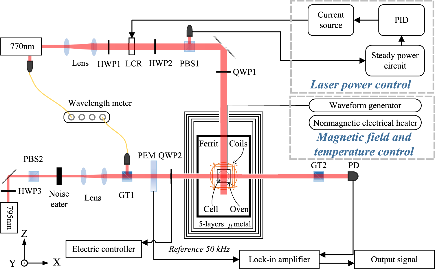
Experimental settings of SERF atomic magnetometer. (LCR is liquid crystal half-wave variable retarders, PBS is polarization beam splitter, PEM is Photoelastic Modulator, PD is photodiode, PID is process identifier, GT is Glan-Taylor prism, WG is waveform generator, HWP is half-wave plate, and QWP is quarter-wave plate).
A pump laser was fabricated from a distributed brag reflector laser (DBR-770, Uniquanta) with a wavelength of 770.108 nm, where the pumping optical power density was 352 mW/cm2 and the diameter was 12 mm. At first, the K atoms were pumped by the pump laser, which is circularly polarized. Subsequently, the Rb atoms were pumped through the spin exchange while the K atoms and Ne atoms were pumped through the spin exchange with Rb atoms. The probe laser was fabricated using a distributed brag reflector laser (DBR-795, Uniquanta) with a wavelength of 795.531 nm, which is very detuned compared to the Rb D1 resonance line. The optical power density of probe laser was 4.81 mW/cm2 and the diameter was 3 mm. The wavelength of the pump and probe lasers were monitored using a wavelength meter (HighFinesse-WS7). Further, the phase of the probe laser was modulated using a photoelastic modulator (PEM-100, Hinds Instruments) into a high frequency, wherein the low frequency noise could be suppressed in the SERF atomic magnetometer.
In our experiments, the circularly polarized component of the probe laser was suppressed before pumping the alkali metal atoms based on the theory in Section 2. A triangular wave magnetic field (with a peak-to-peak value and frequency of the triangular wave magnetic field in Z-axis set to 400 nT and 33.3 mHz, respectively) in the Z-axis were supplied and the rotation angle of QWP2 was adjusted using an electric control mirror frame (AG-UC2 Agilis, Newport). Rotating the QWP2, the output signal protrudes upwards and downwards. When the output signal remains in a line, the probe laser pumping effect is regarded as being suppressed and the QWP2 is in the original position. Based on this position, clockwise rotation and anti-clockwise rotation is signed as + and –, respectively. The angle of QWP2 frame was rotated at every 0.5°, and the DOP was measured by a polarization analyzer (PAX1000IR1/M, Thorlabs). Finally, the light shift in the pumping direction and at the compensation point were measured and analyzed.
4 Measurement results and discussion
According to the analysis in Section 2, the circularly polarized component can be adjusted by a QWP. When a triangular wave magnetic field along the Z-axis is added into the cell, the waveform of the output signal can be used to distinguish whether the circular polarization component of the outgoing laser is completely compensated. The peak-to-peak value and frequency of the triangular wave magnetic field along Z-axis were set to 400 nT and 33.3 mHz, respectively. Based on (3), the response of the output signal was the same in the rising and falling range of the triangular wave magnetic field. Thus, the half a cycle output signal and triangular wave magnetic field in half a cycle were obtained, as shown in Figure 3.
FIGURE 3
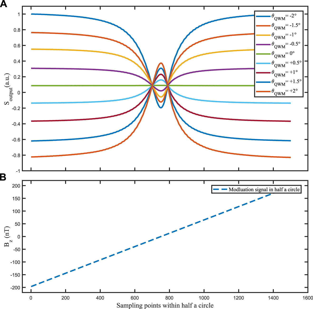
(A) The output signal with a triangular wave magnetic field in the Z-axis is different at different rotated angles of QWP2. The peak and valley of the output signal represents the different compensated states of the circularly polarized component of the probe laser. When the output signal is flat, the circularly polarized component of the probe laser is considered to be totally suppressed and the position of QWP2 is fixed. (B) The modulated triangular wave magnetic field in half a cycle. (The peak-to-peak value 2Bz0 and frequency of the triangular wave magnetic field in the Z-axis are set to 400 nT and 33.3 mHz, respectively).
As shown in Figure 3A, there were three types of shapes observed in the output signal: peaks, valleys, and flat forms. θ is the rotation angle of QWP2 based on the reference position θQWP = 0, which indicated that there was no response in the output signal with the magnetic field. At that time, the circularly polarized component of the probe laser was considered to be totally suppressed. When the QWP2 was rotated in the positive direction, a peak was observed in the output signal. Whereas, when the QWP was rotated in the negative direction, a valley was observed in the output signal. These situations are defined as over- and under-compensated states, respectively. With the increase in the rotation angle, the characteristics of peaks and valleys became increasingly obvious.
Further, the DOP of the probe laser emitted from the QWP was linear with the rotation angle of QWP2, which was measured using a polarization analyzer. As shown in Figures 3A, 4, when the circularly polarized component of the probe laser was considered to be totally suppressed, the rotation angle of QWP2 was equal to zero and the DOP of the probe laser after being suppressed was 0.9886 ± 5.7E-5. In an ideal situation, the DOP of the probe laser after being suppressed should be 1. However, there was a small difference between the ideal and measured values.
FIGURE 4
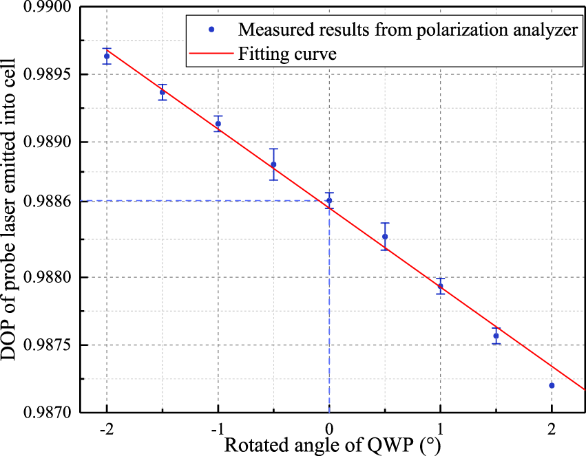
Degree of polarization of probe laser measured by a polarization analyzer at different rotation angles of QWP2. Measured dates are shown in blue and the fitting curve is in red.
Furthermore, Lz and Bc are the significant parameters considered for evaluating the performance of the proposed system. As shown in Figure 5, these parameters were measured and compared at different DOPs of the probe laser when the pumping laser was working [21]. The red and blue points represent the measured results of Lz and Bc, respectively. With an increase in the DOP of the probe laser, the light shift Lz generally fluctuated in the horizontal direction implying that the light shift Lz was not affected by the change in DOP. With the increase in the DOP of the probe laser, a compensation point Bc was observed at the position θQWP = 0.
FIGURE 5
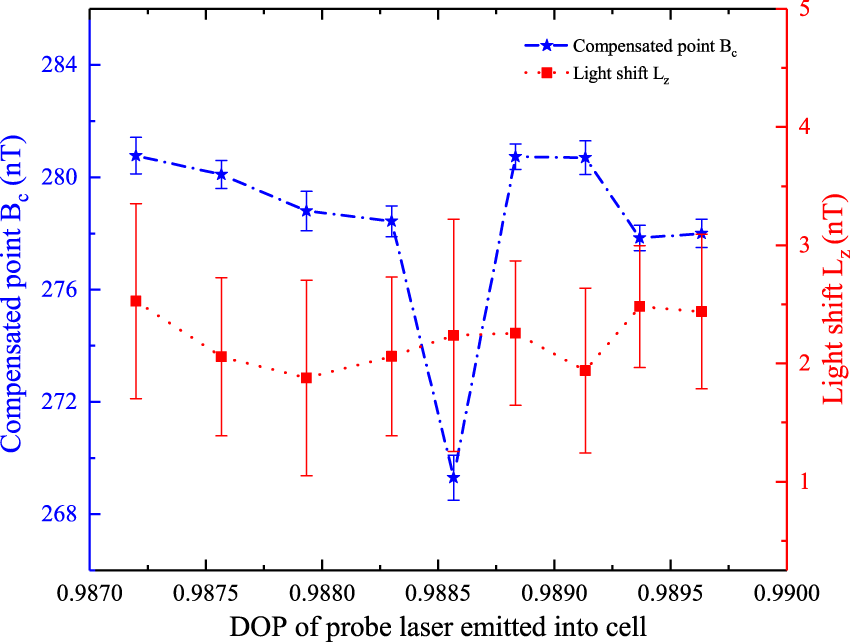
The compensated point Bc and light shift Lz measured in different DOP of the probe laser emitted into the cell. The compensated point Bc is shown in blue and light shift is shown in red.
Based on the fitting equation [16]:where Lx is the value of the light shift along the X-axis. , γe and Bc are the total electron relaxation rate, gyromagnetic ratios of electrons, and compensation point, which have been specifically introduced in our manuscript. Byc is the compensated magnetic field along the Y-axis and By is the residual magnetic field along the Y-axis. By adjusting the power density of the probe laser in different frequencies, By can be fitted through this in-situ calibrated method. The Lx in different positions of QWP2 can be calculated and shown as the next Figure 6.
FIGURE 6
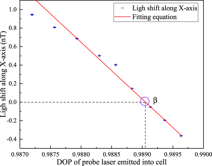
The light shift along the X-axis in different DOPs of the probe laser emitted in to the cell.
As shown in Figure 6, the light shift along the X-axis Lx is decreased with the increasing of DOP, and a zero point exists. The zero point is circled in purple and named β. At the point β, the Lx is equal to zero and the corresponding horizontal coordinate is 0.9891. Finally, the Lx is considered to be compensated completely. At the same time, it is considered that the PLPE is suppressed and the magnetic field in the pumping direction is not influenced by the pumping effect in the probe direction.
5 Conclusion
This study developed the theory for the suppression of PLPE and the related parameters of a SERF atomic magnetometer were analyzed at different DOPs of the probe laser. Changing the angle of QWP2 and adding a triangular modulated magnetic field to the alkali atoms resulted in the suppression point being determined when the response of the output signal remained flat. However, the DOP was not equal to the suppression point. In addition, based on an analysis of Bc, the influence of PLPE on the magnetic field along the pumping direction was found to be the least at the suppression point. In the future research, further study of the relationship between the magnetic compensation point and DOP will be conducted. Finally, we hope to improve the sensitivity of SERF atomic magnetometers through the study of PLPE.
Statements
Data availability statement
The original contributions presented in the study are included in the article/Supplementary Material, further inquiries can be directed to the corresponding author.
Author contributions
Conceptualization, QC and YZ; Methodology, QC; Validation, QC; Formal analysis, BH; Investigation, RL and JL; Data curation, RL and JL; Writing—original draft preparation, QC; Writing—review and editing, QC and BH; Supervision, YZ; Project administration, YZ; Funding acquisition, YZ. All authors contributed to the article and approved the submitted version.
Funding
This work was supported by the National Natural Science Foundation of China (Grant No. 62003020).
Conflict of interest
The authors declare that the research was conducted in the absence of any commercial or financial relationships that could be construed as a potential conflict of interest.
Publisher’s note
All claims expressed in this article are solely those of the authors and do not necessarily represent those of their affiliated organizations, or those of the publisher, the editors and the reviewers. Any product that may be evaluated in this article, or claim that may be made by its manufacturer, is not guaranteed or endorsed by the publisher.
References
1.
Allred JC Lyman RN Kornack TW Romalis MV . High-sensitivity atomic magnetometer unaffected by spin-exchange relaxation. Phy Rev Lett (2002) 89:130801. 10.1103/PhysRevLett.89.130801
2.
Budker D Romalis M . Optical magnetometry. Nat Phy (2007) 3:227–34. 10.1038/nphys566
3.
Jiang M Su H Garcon A Peng X Budker D . Search for axion-like dark matter with spin-based amplifiers. Nat Phy (2021) 17:1402–7. 10.1038/s41567-021-01392-z
4.
Su H Wang Y Jiang M Ji W Fadeev P Hu D et al Search for exotic spin-dependent interactions with a spin-based amplifier. Sci Adv (2021) 7:eabi9535. 10.1126/sciadv.abi9535
5.
Kim YJ Chu PH Savukov I Newman S . Experimental limit on an exotic parity-odd spin- and velocity-dependent interaction using an optically polarized vapor. Nat Commun (2019) 10:2245. 10.1038/s41467-019-10169-1
6.
Zhang J Wang Y Wang C Zhou Z Li W . Excitation circuit with negative feedback for a borehole 4 He optically pumped sensor based on an ELM–hammerstein model. IEEE Sensors J (2023) 23:2021–30. 10.1109/JSEN.2022.3228729
7.
Wang K Zhang K Zhou B Lu F Zhang S Yan Y et al Triaxial closed-loop measurement based on a single-beam zero-field optically pumped magnetometer. Front Phy (2022) 10:1059487. 10.3389/fphy.2022.1059487
8.
Sheng J Wan S Sun Y Dou R Guo Y Wei K et al Magnetoencephalography with a Cs-based high-sensitivity compact atomic magnetometer. Rev Sci Instrum (2017) 88:094304. 10.1063/1.5001730
9.
Xing B Sun C Liu Z Zhao J Lu J Han B et al Probe noise characteristics of the spin-exchange relaxation-free (SERF) magnetometer. Opt Exp (2021) 29:5055. 10.1364/OE.416797
10.
Xing B Lu J Sun C Yu T Wu Y Gao Y et al Suppression of the magnetic noise response caused by elliptically polarized light in an optical rotation detection system. Opt Exp (2022) 30:3854. 10.1364/OE.449951
11.
Happer W Mathur BS . Off-resonant light as a probe of optically pumped alkali vapors. Phy Rev Lett (1967) 18:577–80. 10.1103/PhysRevLett.18.577
12.
Appelt S Baranga ABA Erickson CJ Romalis MV Young AR Happer W . Theory of spin-exchange optical pumping of 3 He and 129 Xe. Phy Rev A (1998) 58:1412–39. 10.1103/PhysRevA.58.1412
13.
Bao G Kanta D Antypas D Rochester S Jensen K Zhang W et al All-optical spin locking in alkali-metal-vapor magnetometers. Phy Rev A (2022) 105:043109. 10.1103/PhysRevA.105.043109
14.
Chen Y Quan W Duan L Lu Y Jiang L Fang J . Spin-exchange collision mixing of the K and Rb ac Stark shifts. Phy Rev A (2016) 94:052705. 10.1103/PhysRevA.94.052705
15.
Fu Y Fan W Ruan J Liu Y Lu Z Quan W . Effects of probe laser intensity on co-magnetometer operated in spin-exchange relaxation-free regime. IEEE Tran Instrum Meas (2022) 71:1–7. 10.1109/TIM.2022.3144738
16.
Xing L Quan W Song T Cai Q Ye W . A measurement method of transverse light-shift in atomic spin co-magnetometer. App Phy B (2022) 128:69. 10.1007/s00340-022-07791-1
17.
Driehuys B Cates GD Miron E Sauer K Walter DK Happer W . High-volume production of laser-polarized 129Xe. App Phy Lett (1996) 69:1668–70. 10.1063/1.117022
18.
Heng X Wei K Zhao T Xu Z Cao Q Huang X et al Ultrasensitive optical rotation detection with closed-loop suppression of spin polarization error. IEEE Tran Instrum Meas (2023) 72:1–12. 10.1109/TIM.2023.3237208
19.
Wei Y Zhai Y Li R Liu S Fan W Quan W . Measurement and suppression of transverse optical pumping in a spin-exchange relaxation-free Co-magnetometer. IEEE Tran Instrum Meas (2022) 72:1. 10.1109/TIM.2022.3224540
20.
Liu S Wang R Yuan L Wu J Yuan Q Zhu J et al Transverse light-shift in a spin-exchange relaxation-free co-magnetometer: Measurement, decoupling, and suppression. Opt Exp (2022) 30:15310. 10.1364/OE.456937
21.
Wei K Zhao T Fang X Xu Z Zhai Y Quan W et al Broadening of magnetic linewidth by spin-exchange interaction in the K-Rb- 21 Ne comagnetometer. Opt Exp (2020) 28:32601. 10.1364/OE.404259
22.
Kornack TW Ghosh RK Romalis MV . Nuclear spin gyroscope based on an atomic comagnetometer. Phy Rev Lett (2005) 95:230801. 10.1103/PhysRevLett.95.230801
Summary
Keywords
spin exchange relaxation free atomic magnetometer, pumping effect, probe laser system, degree of polarization, quarter wave plate
Citation
Cao Q, Zhai Y, Huang B, Li R and Li J (2023) The suppression of the probe laser pumping effect in SERF atomic magnetometer. Front. Phys. 11:1181399. doi: 10.3389/fphy.2023.1181399
Received
07 March 2023
Accepted
22 May 2023
Published
01 June 2023
Volume
11 - 2023
Edited by
Huan Yang, Shandong University, China
Reviewed by
Ben Edward Sauer, Imperial College London, United Kingdom
Lingxiang He, Innovation Academy for Precision Measurement Science and Technology (CAS), China
Updates
Copyright
© 2023 Cao, Zhai, Huang, Li and Li.
This is an open-access article distributed under the terms of the Creative Commons Attribution License (CC BY). The use, distribution or reproduction in other forums is permitted, provided the original author(s) and the copyright owner(s) are credited and that the original publication in this journal is cited, in accordance with accepted academic practice. No use, distribution or reproduction is permitted which does not comply with these terms.
*Correspondence: Yueyang Zhai, yueyangzhai@buaa.edu.cn
Disclaimer
All claims expressed in this article are solely those of the authors and do not necessarily represent those of their affiliated organizations, or those of the publisher, the editors and the reviewers. Any product that may be evaluated in this article or claim that may be made by its manufacturer is not guaranteed or endorsed by the publisher.