Abstract
In this paper a novel THz fiber polarization splitter based on anti-resonant hollow-core fiber with asymmetric dual-suspended cores has been proposed. For the proposed polarization splitter, the ultra-low confinement loss and great polarization splitting performance in the THz band can be achieved, which benefits from the good combination of anti-resonance mechanism with refractive index guidance mechanism. In order to confine the THz wave well in the central large air hole, 8 sets of anti-resonance rings are introduced into the cladding of the fiber. Moreover, the asymmetric dual-suspended cores are used to control the polarization state of the guiding light for enhancing the polarization splitting effect, which exists in the central large air hole of anti-resonant hollow-core fiber. One of the dual cores is designed with a symmetrical structure to reduce the birefringence effect. The other core is designed with an asymmetric structure to increase that in the THz band. The numerical simulations results show that the THz polarization splitter with a length of 0.37 cm is realized in the operating band around 1 THz by optimizing the geometric structure of the dual-suspended-core fiber, and the confinement losses of both x and y polarization modes are lower than 6 × 10⁻³ dB/cm. Furthermore, the working bandwidth at the center frequency of 1 THz can reach ∼0.06 THz, and the extinction ratio is better than 20 dB. The proposed THz polarization splitter has the characteristics of special short length, low loss and broad bandwidth. In conclusion, it has some potential applications of polarization devices in the field of optical fiber sensing and optical fiber communications.
1 Introduction
Terahertz (THz) is an electromagnetic wave with a frequency within 0.1–10 THz or a wavelength within 3 mm–30 µm [1, 2]. THz band is between microwave and infrared light. This band belongs to the transition area from electronics technology to photonics technology, therefore, it has the advantages of both optical and microwave communication [3, 4]. THz transmission in free space causes a variety of adverse losses and significantly reduced transmission efficiency due to coupling with atmospheric components. To solve this problem, several waveguides have been proposed, including metallic wires, hollow metals, parallel metal plates, solid-core fibers, porous-core fibers, hollow fibers, etc [5–13]. However, the most likely future devices to guide terahertz are terahertz fibers, especially hollow anti-resonant fibers. Hollow core anti-resonant fibers (HC-ARF) has received a lot of attention in recent years due to their unique and excellent transmission properties such as extremely low transmission loss, low bending loss, low dispersion and high design flexibility [14–16].
The development of THz technology requires not only high-performance THz waveguide technology for efficient transmission of THz waves, but also essential optical devices such as optical switches, modulators and couplers for THz wavelengths. In recent years, THz single polarization fibers and highly birefringent fibers have been extensively studied, however, research on THz wave directional coupling based on HC-ARF is still scarce.
In 2009, Argyros et al [17]. First proposed a dual hollow-core anti-resonant fiber (DHC-ARF). The fiber cladding structure was found to suppress coupling, and in high loss bands, light was able to couple between the cores by coupling to the cladding structure. In 2016, Wheeler, N.V et al. successfully fabricated the first dual hollow anti-resonant fiber with a minimum loss value of 0.5 dB/m and found that a dual-core fiber with high symmetry has the highest coupling level between the two hollow cores and that the anti-resonant guidance mechanism does not prevent the achievement of strong coupling between the two hollow cores [18]. In 2017, X. Huang et al. proposed the first hollow-core air-gap anti-resonant fiber coupler and is expected to be applied to the mid-infrared and ultraviolet regions which are currently limited by the coupling technology, but the coupling length is larger than 20 cm [19]. In 2019, H. I. Stawska et al [20]. An optimized DHC-ARF design with an asymmetric core was proposed. The optical loss is less than 0.3 dB/cm in the transmission band of 1,500–1700 nm, and the coupling length is less than 1 cm. The guidance mechanism of HC-ARF makes it difficult to achieve short-range polarization coupling in the unique band of THz, but it is possible in suspended core fibers. In 2018, Zhu Y F et al. proposed a low-loss terahertz polarization splitter based on an asymmetric dual-suspended-core fiber. The results of a terahertz polarization splitter of 1.27 cm length have been obtained where transmission losses of 0.53 and 0.67 dB are achieved for X and Y polarization modes [21].
In this paper, we propose a novel THz fiber polarization splitter based on anti-resonant hollow-core fiber with asymmetric dual-suspended cores. There are two suspended cores in the cross-section of the fiber, which are slightly different. One of which is an asymmetric structure composed of two hollow cores, and the other core is a symmetrical structure. We introduced the anti-resonant structure into the polarization splitter, and calculate the confinement loss of x-polarized light and y-polarized light in the device with or without the anti-resonant structure, then combined with the absorption loss of the fiber at this time to calculate the overall transmission loss of this device. Next, the length of the polarization splitter is optimized by adjusting the internal structure of the fiber, including the support beam width, core diameter and core spacing, so that the size of the proposed fiber polarization splitter reaches the minimum value. Finally, we also analyzed the extinction ratio and operating bandwidth of the proposed fiber polarization splitter.
2 Structure and parameters
Figure 1 shows the structure of asymmetric dual-core THz polarization splitter. The proposed structure is based on a high air-filling ratio microstructure fiber with a dual subwavelength core suspended via the thin struts in the x and y directions. The width of the thin struts in x direction is d1, and the thickness of the thin struts in the y direction is d2. To ensure the better polarization splitting effect, we set the value of d1 to be less than d2. In the core region, two identical polymer tubes are adhered to each other to create an asymmetry core defined as coreA, the other fiber core does not possess this tubular structure, so a single round solid fiber and two struts to form a symmetrical core defined as core B. The enlarged view of the fiber core as shown in Figure 1B, the outer diameter of core tube is dL, while the inner diameter is denoted as di. In the following, we also discuss the ratio (di/dL) of these two variables. This ratio will affect the birefringence and effective material loss (EML). After setting the structure size of the left core, we set the diameter of the right core to be dR in order to make the two cores achieve phase matching at 1 THz. Next, the outer tubular dielectric tube with diameter of 2 mm can not only prevent the interference of the external environment to the fiber polarization splitter, but also play a role in stabilizing the device structure. The distance between the core A and core B is D1, and the inner diameter of round tube D.
FIGURE 1

(A) Cross section of the proposed dual-core splitter. (B) Enlarged view of the suspended core.
In our study, the value of D is selected as 2 mm for the operating frequency of 1 THz, and the tube thickness is 0.15 mm. Non-polarized cyclic olefin copolymer TOPAS is selected as the background material for this structure, as the grey areas shown in Figure 1. The white areas indicate the dry air, and the refractive index of the air n = 1. The selection of this material depends on some excellent properties for THz waveguides, which include low bulk material loss of 0.2 cm−1 [22], compared with Polymethylmethacrylate (PMMA) material, its material loss can be reduced by about 100 times. Furthermore, in the frequency range of 0.2–1.5 THz, the refractive index of TOPAS is almost a constant, n = 1.5258, which means that TOPAS has low material dispersion in THz band. Last, it has low moisture absorption, good chemical resistance and high transparency, and it is widely used in optical devices [23]. The effects of polarization splitting on the above-mentioned optical fiber device are calculated by using COMSOL Multiphysics 6.1 software based on full-vector finite element method (FEM). In order to absorb the dispersed radiation, improve the calculation accuracy and avoid the influence of external environment, the perfect matching layer (PML) with a diameter of dPML = 0.3 mm is set at the outermost layer of the optical fiber. The free triangular mesh is used to divide the whole calculation area, in the core area, the maximum triangular mesh size is 20 μm, and the number of mesh layers in the perfect matching layer is 6.
3 Simulation results and discussion
The hollow anti-resonant fiber used in this paper can greatly reduce the leakage of light transmitted in the fiber core to the outside of the fiber, so as to reduce the confinement loss of the fiber. The confinement loss can be calculated by finite element method. It can be expressed as [24],
The light guiding mechanism of hollow anti-resonant fiber is similar to the transmission of light in F-P cavity, the guiding light will be reflected and confined within the hollow fiber core as the guided modes. The light meeting a certain resonance frequency will leak out from the fiber core, and the resonance wavelength can be expressed as [25],
Where, t represents the wall thickness of the anti-resonant ring, n2 is the refractive index of quartz capillaries, n2 = 1.5258. M indicating the resonance order, the value is a positive integer greater than 0. When m = 1, the corresponding wavelength is the first-order resonance wavelength. In order to increase the transmission band, the wall thickness t should be as small as possible. In our proposed fiber, the wall thickness t is set to be 16 μm.
We compare the variation of confinement loss with and without anti-resonant ring. Figure 2A shows the variation of the confinement loss of x-polarized light with the thickness of struts. It can be seen from Figure 2A that with the increase of the thickness of struts, the confinement loss of x-polarized light is in a downward trend, regardless of the presence or absence of anti-resonant ring structures. However, when there exists the anti-resonant ring structure, the maximum confinement loss is reduced by 5 times compared to the structure without the anti-resonant ring. Besides, the confinement loss of x-polarized light shows a gradually increasing trend when the strut thickness is greater than 70 μm. By observing the influence of the anti-resonant structure on the confinement loss of y-polarized light, it can be clearly seen from Figure 2B that when the anti-resonant structure is absent, the confinement loss of y-polarized light increases with the increase of strut thickness, while the opposite is true that when the anti-resonant structure is present, with the maximum confinement loss being reduced by a factor of 150 compared to before. The numerical simulation results show that the application of anti-resonant structures in the polarization splitter can greatly reduce the device’s confinement loss, highlighting the great advantage of anti-resonant structures in reducing the overall loss of this optical device.
FIGURE 2
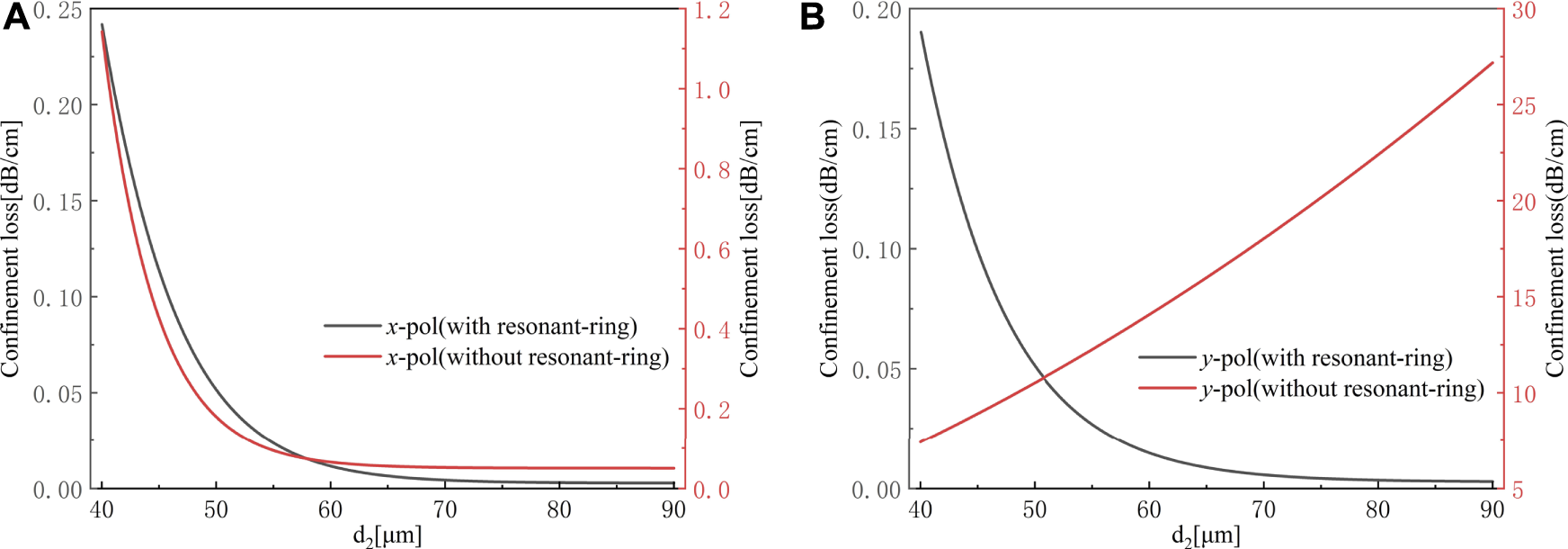
(A) Confinement loss of x-polarized light. (B)y-polarized light.
Next, we use the FEM method to calculate fundamental mode field distributions of the single core fiber, Figure 3A shows the distribution of fundamental mode field of x polarization, Figure 3B shows the field of y polarization. It can be seen from Figure 3 that the fundamental mode is well confined within the fiber core, but the confinement effect of the fiber core on the y-polarization mode seems to be stronger, which can also be demonstrated by the confinement loss value calculated in Figure 6.
FIGURE 3
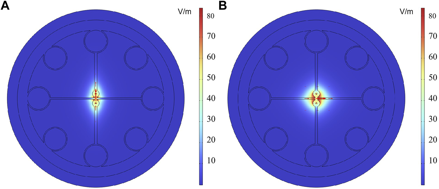
(A) The distribution of fundamental mode field of y polarization. (B) x polarization.
This is because there are sub wavelength air holes in the y direction of the two bonded tubular cores, which leads to the electric field enhancement effect of the y polarization mode at the air hole, resulting in the better confinement of the guided light in the fiber core.
We have studied the influence of different structural parameters on the birefringence of single-core optical fiber. As shown in Figure 4A, where the different colored curves represent different values of the width of the two thin struts in the y-direction. When we observe one of the colored curves separately, the birefringence of single-core fiber gradually decreases as the diameter dL of the tubular core gradually increases. For fiber polarization splitter, the magnitude of the birefringence of the single-core fiber has a significant impact on the polarization splitting performance of this device, and a larger birefringence value means better polarization splitting performance. Therefore, we can find that the smaller the diameter of the tubular core, for the same struts width, the smaller the diameter of the cylindrical core, the larger the birefringence value of the single-core fiber. At the same time, we can also analyze from Figure 4A that when the diameter of the tubular core is fixed, the larger the width of the strut, the greater the birefringence value of the single-core fiber. As shown in Figure 4B, the diameter of tubular core fixed as dL = 100 μm, and gradually increased the width d2 of the strut in the y-direction from the minimum value of 40–90 μm, the birefringence value of single-core fiber also increases gradually, when d2 = 90 μm, the birefringence value reaches its maximum, and at this point, the maximum birefringence valu Bmax = ∼0.09.
FIGURE 4
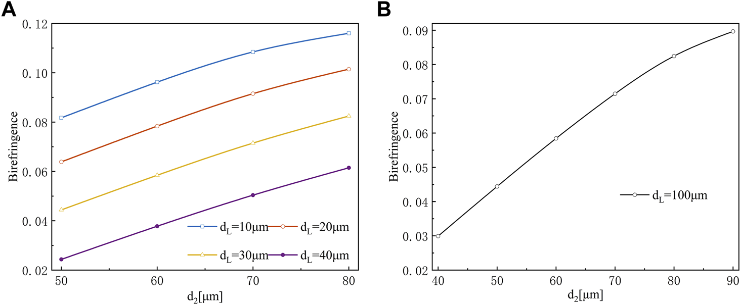
(A) The birefringence with different diameters. (B) When outer diameter of core tube dL is fixed at 100 μm.
Besides, another important parameter for the fiber core structure is the core-cladding ratio q of the fiber core, which represents the ratio between di and do (dL/do). The variation of birefringence with core-cladding ratio q for single-core fibers is shown in Figure 5. It can be seen that the birefringence decreases with the increase of q. The maximum birefringence occurs when q = 0.1, with do = 100 μm, dL = 10 μm, the maximum value of birefringence Bmax = 0.117.
FIGURE 5
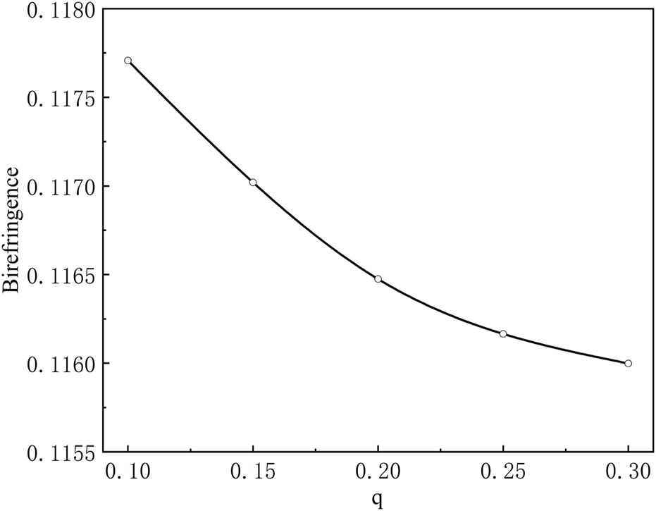
The birefringence with different ratio q (dL/do).
Figure 6 shows the change of confinement loss and effective material absorption loss (EML) of single-core optical fiber with the change of support arm width d2 in the y direction. EML represents the absorption of incident light energy by the material, and a larger EML indicates higher loss in the fiber. The effective material absorption loss can be expressed as [26]:
FIGURE 6
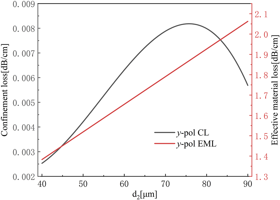
The confinement loss and effective material loss with different diameters.
Where, represents the value of effective material absorption loss (EML), the unit is . and are the dielectric constant and magnetic permeability in vacuum, represents the refractive index of the optical fiber composition material. Indicates the material absorption coefficient, which varies for different materials and directly affects the overall absorption loss of the fiber. Many solid materials exhibit relatively large absorption coefficients in the terahertz band, typically on the order of cm-1 [27–29], while the absorption of dry air to the terahertz wave can be negligible. The material absorption coefficient of TOPAS is about 0.2 cm-1 at 1 THz. He symbol represents the Poynting vector in the z direction, represents the area of the base material part of the cross section of the optical fiber, and represents the overall area inside the optical fiber. As shown in Figure 6, as the width of the supporting arm in the y direction d2 changes, both the confinement loss and the effective material absorption loss (EML) of the single-core fiber vary, the effective material absorption loss refers to the absorption of incident light energy by the material, and a larger EML indicates greater loss of the fiber. With increasing d2, the confinement loss of the fiber gradually increases and reaches a maximum of 0.008 dB/cm when d2 = 70 μm. After reaching the maximum value, the limiting loss gradually decreases with increasing d2. However, the effective material absorption loss of the fiber continues to increase as d2 increases, and reaches its maximum when d2 = 90 μm.
Note that in the numerical simulation results above, the width of the support arm in the x direction, d1, remains unchanged. Let’s fix the value of d1 to 30 μm. On this basis, we observe the results shown in Figure 4 above again, we find that when the width d2 of the support arm in the y direction increases continuously, it indicates that the difference of these struts width in two directions gradually increases. This difference represents the degree of structural asymmetry of the single-core fiber. The larger the difference , the greater the degree of asymmetry in the structure, and it can be expected that the birefringence value will be larger. Following this idea, we considered the effect of the difference in the width of the support arm in the x and y directions on the birefringence of single-core fiber. As shown in Figure 7, the curves with different colors represent different values of the support arm width in the x direction. When the value of d1 is determined, the birefringence value will increase with the increase of d2. The maximum value of birefringence occurs at d1 = 10 μm, d2 = 80 μm. Meanwhile, we can determine the maximum birefringence value Bmax = ∼0.12.
FIGURE 7
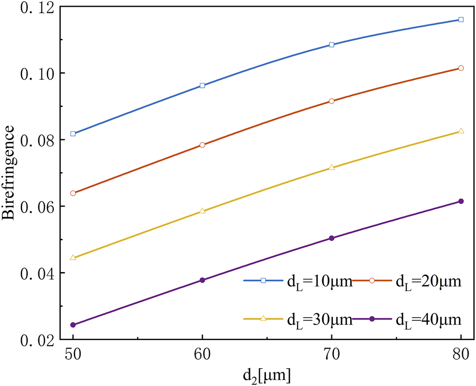
Birefringence of the proposed basic single core fiber at the diameters dL = 10, 20, 30, 40 μm, respectively.
Figure 8 shows the influence of the diameter of the optical fiber core dielectric tube on the confinement loss. It can be seen that larger polymer tube diameter corresponds to smaller confinement loss. When the core diameter dL increases gradually from 100 μm to 150 μm, the confinement loss value CL of y-polarized light decreases from the maximum of ∼2.5 × 10⁻³ dB/cm to ∼2.7 × 10⁻⁵ dB/cm, which reduces by about two orders of magnitude. At the same time, the confinement loss also reflects the binding ability of the fiber core to the light guide. It can be observed that when the core diameter dL of the fiber core dielectric tube changes continuously, the confinement loss value of the y-polarized light is always smaller than that of x-polarized light, which also proves that the fiber core has a stronger confinement effect on the y-polarized mode.
FIGURE 8
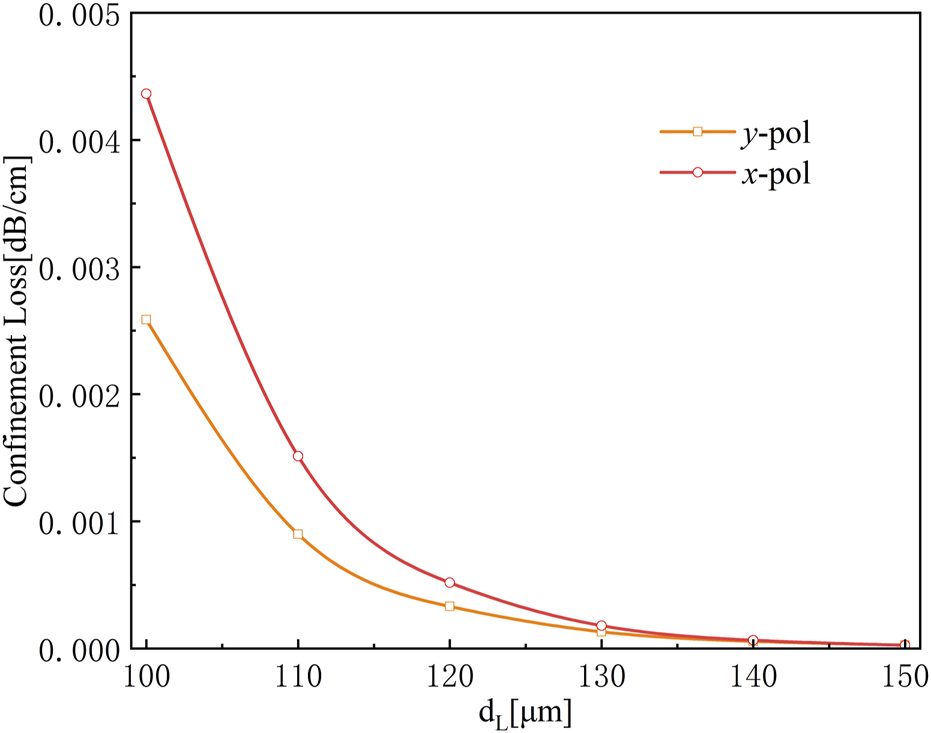
The influence of the diameters dL on the confinement loss for x and y polarization modes.
At the same time, we also studied the influence of the diameter of the optical fiber dielectric tube on the effective material absorption loss. As shown in Figure 9, with the increase of the diameter of the optical fiber dielectric tube, the effective material absorption loss value of the optical fiber gradually increases. When the diameter dL of optical fiber dielectric tube increases from 100 to 150 μm, the effective material absorption loss EML of y-polarized light increases from the minimum 1.38 to 1.63 dB/cm. This change can be obtained from Eq. 3, where a larger the diameter dL of the fiber dielectric tube, represents a larger overlap area between the fiber core material and the guided light resulting in a larger absorption loss of the fiber. Since the fiber core dielectric tubes are arranged along the y-axis and the area in the x direction is smaller, so the effective material absorption loss value of x-polarized light is always smaller than the effective material absorption loss value of y-polarized light.
FIGURE 9
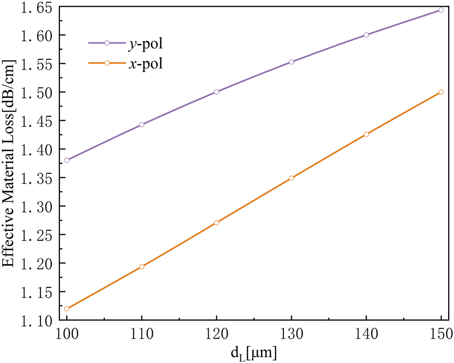
Effective material loss (EML) as a function of the diameters dL for x and y polarization modes.
4 Characteristic analysis of beam splitter
In the previous section, we discussed the variation of the birefringence of single-core fibers under different structural parameters. By adjusting the structural parameters, the birefringence value of single-core fiber can be maximized. To complete the polarizing beam splitter, we add another core on the basis of single-core fiber, which is defined as core B. Core B has a symmetric structure and therefore hardly produce the birefringence. In order to achieve the phase matching between the two core modes, we carefully adjusted the structural parameters of coreB.
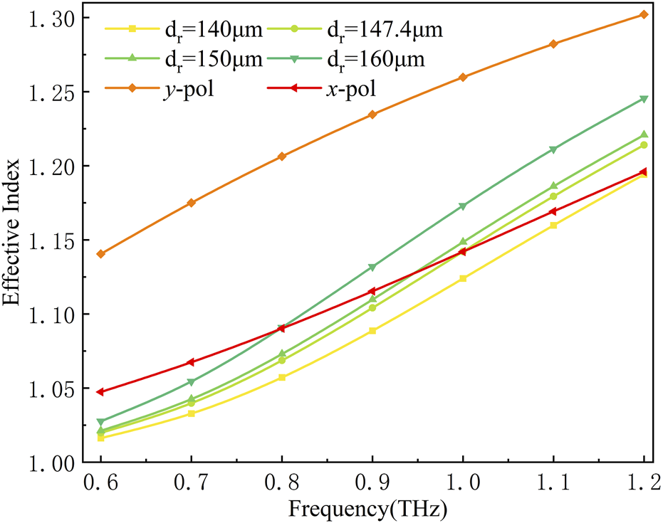
Firstly, in order to minimize the birefringence of core B, we set the thickness of the two support arms in the x and y directions at core B to be the same, both are 30 μm. When we adjust the diameter of core B, the variation of the effective refractive indices of the two cores with the incident light frequency is shown in Figure 10. When the effective refractive index curve of core A intersects with that of core B, the phase matching of the two core modes is achieved. The calculated values of the effective refractive index of the y-polarized light in core A shown in Figure 10 at different frequencies are far greater than the effective refractive index values in all other cases and there is no intersection with other curves, which indicates that y-polarized light in core A does not couple with the guiding mode in core B. However, the effective refractive index curve of x-polarized light in core A intersects with that of core B, as shown in Figure 9. When the diameter of the symmetric core B is dr=140 μm, the focal point of the effective refractive index curve of x-polarized light in core A intersects with that of core B at 1.19 THz, so the resonant frequency of the two cores when fc = 1.19 THz. When dr=147.4 μm, the resonant frequency of the two cores is fc = 1 THz. In addition, when dr=150 μm, the resonant frequency of the two cores is fc = 0.8 THz. It can be seen that with the incident light frequency decreases, the resonant frequency also decreases and the phase matching point moves to the low-frequency region. By adjusting the diameter of core B, the phase matching point of the two cores is moved to 1 THz.
FIGURE 10
Phase matching of x and y polarization in dual-core optical fiber.
The mode field distribution of the four supermodes of the dual-core fiber is shown in Figure 11. It can be seen from the figure that when phase matching occurs, the x-polarized light has a strong coupling effect in the two fiber cores. However, due to the large difference in refractive index between the y-polarized light in the two cores, the y-polarized light is independently transmitted in each core. This indicates that the polarization splitter can be achieved a good polarization splitting effect at this point.
FIGURE 11
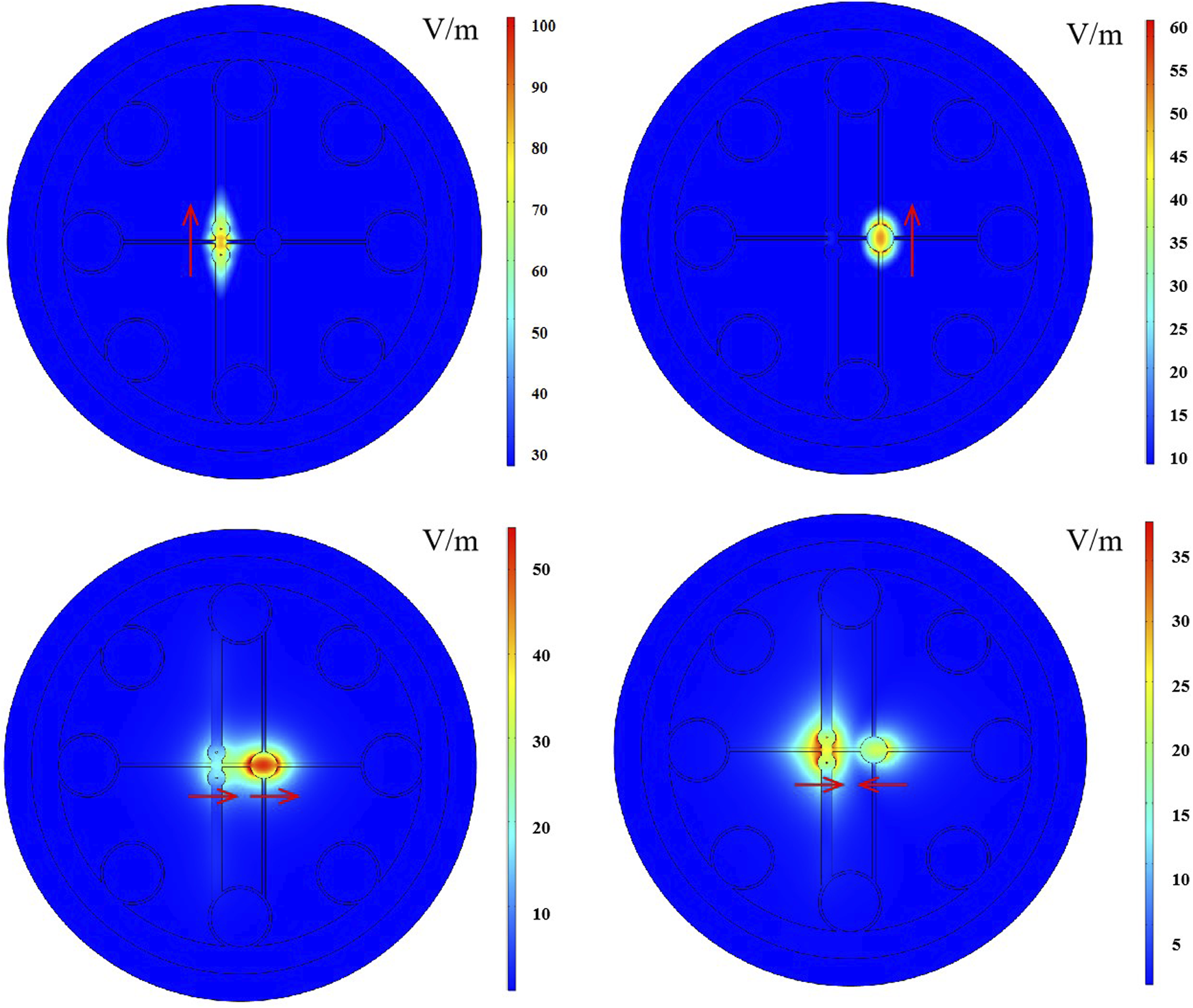
Field distributions of the four modes.
According to the mode coupling theory, the maximum coupling efficiency of the two polarization states of the guiding light in the dual-core fiber can be calculated by using Eq. 4:
The equation above represents the maximum coupling efficiency, is the maximum coupling efficiency value, is the coupling coefficient, and is the phase mismatch constant of the polarization mode i. And and are the effective refractive indexes of the even mode and the odd mode of i polarization, and are the effective refractive indexes of the core A and core B in the state of i polarization, respectively. Figure 12 shows the variation of maximum coupling efficiency for the y-polarization mode of the two cores at 1 THz with respect to the distance between the cores D. As the distance D between the two cores increases, the maximum coupling efficiency of the y polarization mode decreases gradually from the maximum normalized coupling efficiency of 0.22 to the minimum of 5.72 × 10⁻⁵, it can be observed that when D = 240 μm, the maximum coupling efficiency of y polarization mode is only 1 × 10⁻³ (0.1%). The lower maximum coupling efficiency for the y-polarization mode indicates that it is difficult for this mode to couple between the two cores, and a polarization splitter with high extinction ratio can be obtained at this point.
FIGURE 12
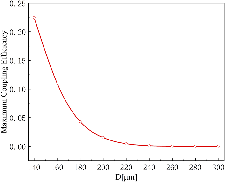
The maximum y-Polarization coupling efficiency with distance D1 between the two cores.
In addition, the coupling length is defined as the length of the device required for the phase difference between the even mode and odd mode of a certain polarization light to reach π, and its calculation formula is:
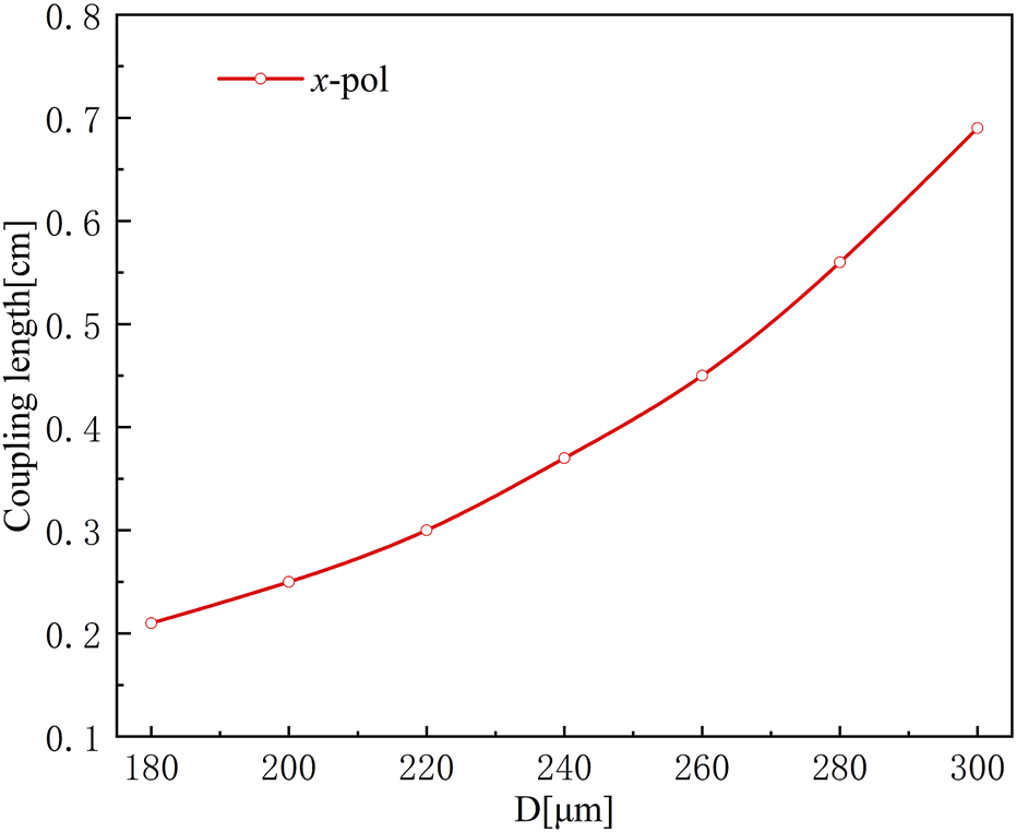
In the above formula, is the wavelength of the incident light. When the incident light wavelength is 0.3 mm (a frequency of 1 THz), the coupling length of the x-polarization mode varies with the distance D between the two fiber cores, as shown in Figure 13. With the distance D increases, the coupling length of the x-polarization mode also gradually increases. When D = 240 μm, the coupling length between the two fiber cores is 0.37 cm. This indicates that the light in the two polarization directions can be effectively separated after passing through the 0.37 cm long polarization splitter.
FIGURE 13
The coupling length as a function of the distance D1.
Transmission loss is also the key parameter of THz polarization splitting performance, which can be calculated by the following formula:
Where, refers to the total loss of the optical fiber in the direction of polarization i, including both effective material absorption loss and confinement loss. Since the confinement loss can be ignored when the absorption loss of the effective material is relatively large, the transmission loss of the polarization splitter is only 0.577 dB at the length of 0.37 cm.
When the fundamental mode power transmitted to core A is Pin, the output power of core A and core B is shown as follows [30]:
Figures 14A, B show that when the frequency of light emitted into core A is 1 THz, the normalized power transfer along propagation length in the core A and B. As the transmission distance increases, the power of the y-polarization mode in fiber core A gradually decreases. This is due to the inherent absorption loss of the fiber core, which causes optical loss. On the other hand, the x-polarization mode in fiber core A will undergo periodic transmission between the two fiber cores. When the coupling length of the x-polarization mode is 0.37 cm, the two polarization modes are effectively separated.
FIGURE 14
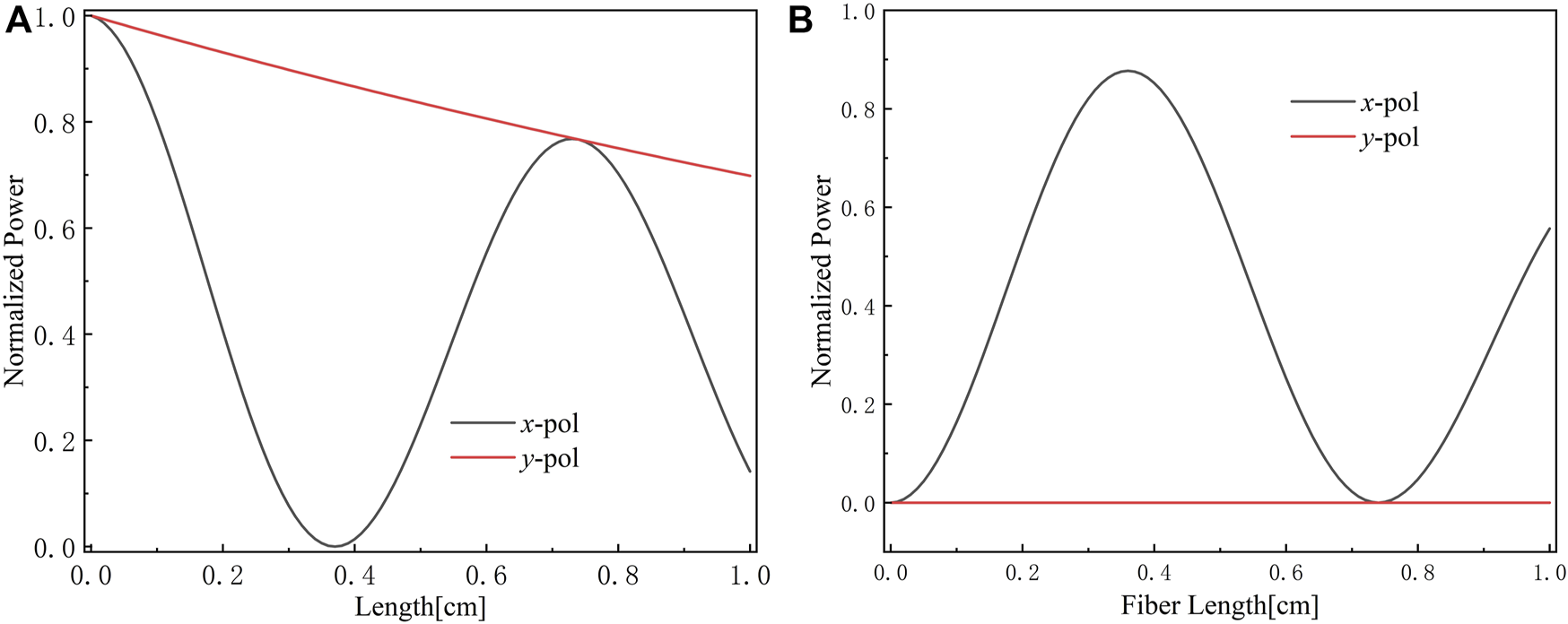
Normalized power transfers in the core A (A) and the core B. (B) as a function of fiber length.
In addition, the Extinction Ratio (ER) of the proposed polarization splitter is also considered. ER is defined as the power ratio between the undesired and expected polarization modes in each output fiber core, the ERs of core A and core B can be calculated by the following equations respectively [31]:
As shown in Figure 15A, for the y-polarization mode in core A at the center frequency of 1THz, ERy = −151.43 dB, and Figure 15B for the x-polarization mode in core B at the center frequency of 1THz, ERx = −30.00 dB. When the frequency is within the range of 0.98–1.04, the extinction ratio of both x-pol and y-pol are better than −20 dB, and the bandwidth of the x and y polarization modes are approximately ∼0.06 THz.
FIGURE 15
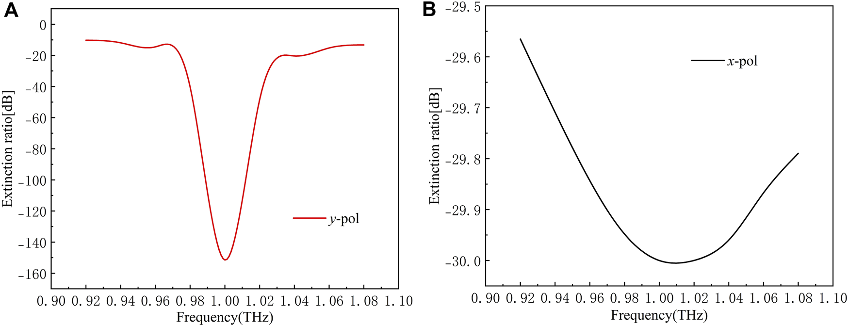
ERs of x-pol (A) and y-pol (B)versus frequency of 0.37-cm-long polarization splitter.
For the above polarization splitter, Suspended-core THz fibers of similar structure have been successfully drawn, and the same drilling technique can be used to obtain the cladding structure of our design [32]. The reported extrusion technique can be used to fabricate almost any structure and designed for larger fiber sizes [33], and the 3D printing technique can also be done precisely for the preparation of fiber [34].
5 Conclusion
In conclusion, in this paper we proposed a novel THz fiber polarization splitter based on anti-resonant hollow-core fiber with asymmetric dual-suspended cores. We innovatively combine the anti-resonant structure with the traditional fiber polarization splitter, effectively reducing the confinement loss of this device. By adjusting the core diameter, a minimum y-polarization confinement loss of ∼2.7 × 10⁻⁵ dB/cm can be achieved. Furthermore, our results confirm that the birefringence of the asymmetric single-core fiber can reach ∼0.09 at 1 THz. The coupling length of the proposed asymmetric dual-core THz polarizer at 1 THz is 0.37 cm, with the ER values of ERx = −30.00 dB and ERy = −151.43 dB for the x- and y-polarization modes, respectively. And the frequency band with the ERs better than −20 dB can reach ∼0.06 THz. Therefore, our proposed THz fiber polarization splitter has the potential applications in the fields of fiber communications and fiber sensing.
Statements
Data availability statement
The raw data supporting the conclusion of this article will be made available by the authors, without undue reservation.
Author contributions
YL and ZH contribute equally to this article. All authors contribution to the article and approved the submitted version.
Funding
This work was partially supported by the Fundamental Research Funds for the Central Universities to the Harbin Engineering University (3072022TS2510), Natural Science Foundation of Heilongjiang Province (LH2019F014), 111 Project to the Harbin Engineering University (B13015).
Conflict of interest
The authors declare that the research was conducted in the absence of any commercial or financial relationships that could be construed as a potential conflict of interest.
Publisher’s note
All claims expressed in this article are solely those of the authors and do not necessarily represent those of their affiliated organizations, or those of the publisher, the editors and the reviewers. Any product that may be evaluated in this article, or claim that may be made by its manufacturer, is not guaranteed or endorsed by the publisher.
References
1.
TonouchiM, Cutting-edge terahertz technology. Nat Photon (2007) 1(2):97–105. 10.1038/nphoton.2007.3
2.
IslamMSCordeiroCFrancoMSultanaJCruzALSAbbottD. Terahertz optical fibers [Invited]. Opt Express (2020) 28(10):16089–117. 10.1364/oe.389999
3.
BründermannEHübersHWKimmittMF, Terahertz techniques [M]. Springer Berlin Heidelberg (2012).
4.
AkyildizIFJornetJMChongH. Terahertz band: Next frontier for wireless communications. Phys Commun (2014) 12(4):16–32. 10.1016/j.phycom.2014.01.006
5.
WangKMittlemanDM. Metal wires for terahertz wave guiding. Nature (2004) 432(7015):376–9. 10.1038/nature03040
6.
McGowanRWGallotGGrischkowskyD. Propagation of ultrawideband short pulses of terahertz radiation through submillimeter-diameter circular waveguides. Opt Lett (1999) 24(20):1431–3. 10.1364/ol.24.001431
7.
MendisRGrischkowskyD. Undistorted guided-wave propagation of subpicosecond terahertz pulses. Opt Lett (2001) 26(11):846–8. 10.1364/ol.26.000846
8.
JamisonSPMcgowanRWGrischkowskyD. Single-mode waveguide propagation and reshaping of sub-ps terahertz pulses in sapphire fibers. Appl Phys Lett (2000) 76(15):1987–9. 10.1063/1.126231
9.
AnthonyJLeonhardtRArgyrosALargeMCJ. Characterization of a microstructured Zeonex terahertz fiber. J Opt Soc America B (2011) 28(5):1013–8. 10.1364/josab.28.001013
10.
LaiCHHsuehYCChenHWHuangYJChangHCSunCK. Low-index terahertz pipe waveguides. Opt Lett (2009) 34(21):3457–9. 10.1364/ol.34.003457
11.
LuJYYuCPChangHCChenHWLiYTPanCLet alTerahertz air-core microstructure fiber. Appl Phys Lett (2008) 92(6):064105. 10.1063/1.2839576
12.
DupuisAStoefflerKUngBDuboisCSkorobogatiyM. Transmission measurements of hollow-core THz Bragg fibers. J Opt Soc America B (2011) 28(4):896–907. 10.1364/josab.28.000896
13.
AtakaramiansSShahraamAVFischerBMAbbottDMonroTM. Porous fibers: A novel approach to low loss THz waveguides. Opt Express (2008) 16(12):8845–54. 10.1364/oe.16.008845
14.
PolettiF, Nested antiresonant nodeless hollow core fiber. Opt Express (2014) 22(20):23807–28. 10.1364/oe.22.023807
15.
LuWLouSArgyrosA, Investigation of flexible low-loss hollow-core fibres with tube-lattice cladding for terahertz radiation. IEEE J Sel Top Quan Electron. (2016) 22(2):214–20. 10.1109/jstqe.2015.2493964
16.
SettiVVincettiLArgyrosA, Flexible tube lattice fibers for terahertz applications. Opt Express (2013) 21(3):3388–99. 10.1364/oe.21.003388
17.
ArgyrosLeon-Savalvan EijkelenborgASGMAvan EijkelenborgMA. Twin-hollow-core optical fibres. Opt Commun (2009) 282:1785–8. 10.1016/j.optcom.2009.02.002
18.
WheelerNVBradleyTDHayesJRJasionGTChenYSSandoghchiRet alDual hollow-core anti-resonant fibres, In Proceedings Volume 9886, Micro-Structured and Specialty Optical Fibres IV, Bellingham, WA, USA, 9886. Brussels, Belgium: SPIE (2016).
19.
HuangXMaJTangDYooS, Hollow-core air-gap anti-resonant fiber couplers. Opt Express (2017) 25(23):29296–306. 10.1364/oe.25.029296
20.
StawskaHIPopendaMA. A dual hollow core antiresonant optical fiber coupler based on a highly birefringent structure-numerical design and analysis. Fibers (2019) 7:109. 10.3390/fib7120109
21.
ZhuYFLinXRaoCFZhongHLuoHMChenYHet alLow-loss terahertz polarization splitter based on an asymmetric dual-suspended-core fiber[J]. Opt Eng (2018) 57(08):086112.
22.
BaoHLNielsenKRasmussenHKJepsenPUBangO, Fabrication and characterization of porous-core honeycomb bandgap THz fibers. Opt Express (2012) 20(28):29507–17. 10.1364/oe.20.029507
23.
HasanMRIslamMAAnowerMSRazzakSM, Low-loss and bend-insensitive terahertz fiber using a rhombic-shaped core. Appl Opt (2016) 55(30):8441–7. 10.1364/ao.55.008441
24.
YuHChongYZhangPMaJ. A D-shaped fiber SPR sensor with a composite nanostructure of MoS2-graphene for glucose detection. Talanta (2020) 219:121324. 10.1016/j.talanta.2020.121324
25.
LiQFengYJSunYHChangZWangYSPengWJet al “Simulation of the structural parameters of anti-resonant hollow-core photonic crystal fibers.” Curr Opt Photon6.2 (2022): 143–50.
26.
LuoJFChenSSQuHKSuZLLiLTianFJ. Highly birefringent single-mode suspended-core fiber in terahertz regime. J Lightwave Technol (2018) 36(16):3242–8. 10.1109/jlt.2018.2834458
27.
FischerBMHoffmannM. Broadband THz time-domain spectroscopy of biomolecules [J]. Math Phys (2005) 246.
28.
JinYSKimGJJeonSG. Terahertz dielectric properties of polymers [J]. J Korean Phys Soc (2006) 49(2):513–7.
29.
CunninghamPDValdesNNVallejoFAHaydenLMPolishakBZhouXHet alBroadband terahertz characterization of the refractive index and absorption of some important polymeric and organic electro-optic materials. J Appl Phys (2011) 109(4):043505–0435055. 10.1063/1.3549120
30.
ChenHZYanGFForsbergEHeSL. Terahertz polarization splitter based on a dual-elliptical-core polymer fiber. Appl Opt (2016) 55(23):6236–42. 10.1364/ao.55.006236
31.
SaitohKSatoYKoshibaM. Polarization splitter in three-core photonic crystal fibers. Opt Express (2004) 12(17):3940–6. 10.1364/opex.12.003940
32.
MazhorovaAMarkovANgAChinnappanRSkorobogataOZourobMet alLabel-free bacteria detection using evanescent mode of a suspended core terahertz fiber. Opt Express (2012) 20(5):5344–55. 10.1364/oe.20.005344
33.
LianZHorakPFengXXiaoLFramptonKWhiteNet alNanomechanical optical fiber. Opt Express (2012) 20(28):29386–94. 10.1364/oe.20.029386
34.
YangSShengXZhaoGLouSGuoJ. 3D printed effective single-mode terahertz antiresonant hollow core fiber. IEEE Access IEEE Access (2021) 2021(9):29599–608. 10.1109/access.2021.3059782
Summary
Keywords
THz optical fiber, anti-resonant fiber, suspension core fiber, confinement loss (CL), polarization beam spillter, extinction ratio
Citation
Lu Y, Han Z, Tian F, Zeng Z, Chen Y, Xiu Z, Liu S, liu C, Yang X and Zhang J (2023) A THz fiber polarization splitter based on anti-resonant hollow-core fiber with the asymmetric dual-suspended cores. Front. Phys. 11:1189506. doi: 10.3389/fphy.2023.1189506
Received
19 March 2023
Accepted
26 April 2023
Published
12 May 2023
Volume
11 - 2023
Edited by
Xianzhong Chen, Heriot-Watt University, United Kingdom
Reviewed by
Maksim Melnik, ITMO University, Russia
Kumary Sumi Rani Shaha, Pabna University of Science and Technology, Bangladesh
Updates
Copyright
© 2023 Lu, Han, Tian, Zeng, Chen, Xiu, Liu, liu, Yang and Zhang.
This is an open-access article distributed under the terms of the Creative Commons Attribution License (CC BY). The use, distribution or reproduction in other forums is permitted, provided the original author(s) and the copyright owner(s) are credited and that the original publication in this journal is cited, in accordance with accepted academic practice. No use, distribution or reproduction is permitted which does not comply with these terms.
*Correspondence: Fengjun Tian, fengjuntian@hrbeu.edu.cn
†These authors have contributed equally to this work
Disclaimer
All claims expressed in this article are solely those of the authors and do not necessarily represent those of their affiliated organizations, or those of the publisher, the editors and the reviewers. Any product that may be evaluated in this article or claim that may be made by its manufacturer is not guaranteed or endorsed by the publisher.