 Jianning Han
 Rui Wang*
- School of Information and Communication Engineering, North University of China, Taiyuan, Shanxi, China
Projection display is of relevance for various applications, for example, information communication, encryption and storage. Although numerous optical projection devices have been reported in past years, the realization of switchable acoustic projection display without built-in circuits is a challenge. In this work, we propose a coding composite structure composed of a perforated plate and a coiling-up cavity with six interdigital rigid walls to achieve switchable acoustic projection displays. The configuration can be served as bits ‘0’ and ‘1’ by using forward and backward placements, respectively. The required projection can be displayed as long as the expected image regions are filled with bit ‘1’ and other regions are filled with bit ‘0’. By switching control wave Pc, the projected image is able to be switched from ‘Off state’ to ‘On state’ accordingly. The underlying physical mechanism is the different scattering responses between two coding bits induced by coherent superposition. Our design provides an effective solution for the construction of acoustic projection displays with switchable feature, which may have potential applications in information encryption and storage.
1 Introduction
As an effective approach to display required images or information, projection device plays important roles in many applications including light-emitting diode screens, electronic billboard signage and traffic light. Despite numerous achievements in optical projection displays [1–10], the similar devices in acoustic category have not been widely reported so far, especially for switchable fashion without built-in circuits. The realization of acoustic projection display is of great significant in information storage and communication. Given the advantages of subwavelength scale, flexibility and planer feature, the development of acoustic metasurface provides a possible solution for the design of acoustic projection device.
In past several years, acoustic metasurface (a composite structure with planer configuration) has been demonstrated to be good candidates to achieve various fascinating phenomena, such as beam deflection [11–13], beam focusing [14–19], vortex beam [20], splitting beam [21] and Airy beam [22] by utilizing Helmholtz resonators [23, 24], coiling-up cavities [25], or spiral particles [26]. Owing to the shifts of equivalent refractive index induced by resonance effect, arbitrary phase or amplitude response can be obtained by adopting ultrathin structural design, making it is suitable to be integrated in acoustic devices. To accurately fit the phase or amplitude profile, however, multiple discrete orders are required for designed units, which increases the complexity of the structure. In addition, some harsh parameters may be involved in discrete process, which are hardly to be fabricated by 3D printing technology, and the thermal viscosity loss is non-negligible. Recently, the emergence of coding metasurface offers a simplified method for the realization of wavefront modulation [27–30]. Only two kinds of units with opposite phase responses (0 and π) are needed to serve as coding bit ‘0’ and ‘1’, and numerous beam-shaping behaviors can be achieved as well without complicated design philosophy. Hence, the combination between coding metasurface and acoustic projection displays is expected to be a valuable tool for advanced acoustic devices.
In this work, a composite structure composed of a phase regulator (PR) and an amplitude regulator (AR) is proposed to build switchable acoustic projection devices, through which arbitrary image can be projected by adopting corresponding coding sequences, and the ‘On/Off states’ are capable of switching by additional control wave Pc. To achieve desirable scattering responses for AR and PR, a perforated plate and a coiling-up cavity with six interdigital rigid walls are constructed to modulate the amplitudes and phases of scattering waves continuously. The composite structure can play the roles of bits ‘0’ and ‘1’ by using forward and backward placements, respectively, due to their extremely asymmetric scattering responses induced by coherent superposition, greatly simplifying the design philosophy by using coding acoustic metasurface. The acoustic projection display illustrated in our work may have profound impact on exploring various acoustic information related devices.
2 Theory
To achieve switchable acoustic projection displays, we propose two kinds of unit and encode them as bits ‘0’ and ‘1’. The transmission and reflection coefficients of bit ‘0’ are assumed to be
where Pi and Pc represent input wave and control wave, respectively. Following Eq. 1, it can be deduced that the normalized amplitude of S0 and S1 are 0.5 in the case of only Pi incidence owing to the identical transmission response for bits ‘0’ and ‘1’. When input wave and control wave are incident on them simultaneously, however, the normalized amplitude of S0 and S1 are 0 and 1 owing to the existence of destructive interference in bit ‘0’ and constructive interference in bit ‘1’. Therefore, switchable acoustic projection displays are expected to be obtained by utilizing coherent incident waves with opposite propagating directions.
Here, we intend to construct a model with an asymmetric configuration to act as bits ‘0’ and ‘1’ by using forward and backward placements, respectively, which needs the scattered pressures on both sides of the model agree with those on right side of bits ‘0’ and ‘1’. To achieve this goal, as shown in Figure 1A, we consider a composite structure composed of an AR and a PR. AR is placed on left and right sides of the PR for bits ‘0’ and ‘1’, respectively. Note that the phase (amplitude) response for AR (PR) is fixed when modulating the amplitude (phase) response continuously. For bit ‘0’, the input wave Pi becomes Pi*tA*tP after passing through AR and PR, and the control wave Pc becomes Pc*tP*rA*tP because it first passes through PR, then is reflected by AR, and finally passes through PR again. tP and tA represent the transmittance of PR and AR, and rA represent the reflection of AR. Therefore, the transmission and reflection coefficients of bits ‘0’ and ‘1’ can be expressed as follows:
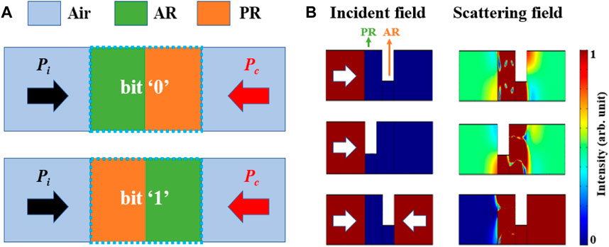
FIGURE 1. (A) Schematic diagrams of bits ‘0’ and ‘1’, where light blue region, green region and orange region are air background, AR and PR, respectively. The black and red arrows present the input wave Pi and control wave Pc. (B) The normalized incident and scattering fields of bits ‘0’ and ‘1’ for one side incidence and both sides incidence. The white arrows indicate the incident directions, and the operating frequency is 3,430 Hz.
From Eq. 2 it can be deduced that the phase difference between R0 and R1 is related to tP, so the asymmetric phase response can be controlled by PR, and the exact values of scattering coefficients (T0, T1, R0, R1) are capable of modulating by AR accordingly. When input wave and control wave are incident on composite structure simultaneously, the scattered pressures on left side of the bits ‘0’ and ‘1’ can be expressed as:
According to Eq. 1, Eq. 3, the relation of S00 = S0 and S11 = S1 can be obtained when the requirements of
To verify above deductions, as shown in Figure 1B, an equivalent medium meeting the conditions of
3 Structural design
To construct desirable composite structure, a practical configuration with phase and amplitude modulation capability is required. Note that the phase (amplitude) response needs to be fixed when the amplitude (phase) response is modulated continuously by AR (PR), and the transmittance of PR should be as high as possible to guarantee the projection quality. As shown in Figures 2A,C, we propose a perforated plate and a coiling-up cavity with six interdigital rigid walls to serve as AR and PR, respectively. The length and width of AR and PR are L = 25 mm and W = 28 mm, which are much smaller than the operating wavelength λ0 (L = 0.25λ0, W = 0.28λ0), and have the advantage of subwavelength scale. To obtain amplitude modulation, the opening size of the perforated plate is a variable from w = 5 mm to w = 25 mm. With the reduction of w, as shown in Figure 2B, the transmitted (reflected) amplitude decreases (increases) gradually owing to the impedance mismatch induced by small opening size, while the transmitted and reflected phase responses are nearly fixed, exhibiting an excellent ability for amplitude modulation independently. As a special case, when w = 10.8 mm the transmitted amplitude is the same as reflected amplitude (
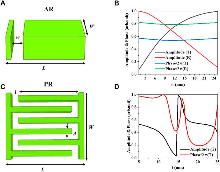
FIGURE 2. Schematic diagrams of (A) AR and (C) PR. AR is a perforated plate and PR is a coiling-up cavity with six interdigital rigid walls. The amplitude and phase responses of (B) AR and (D) PR with the change of w and l. The operating frequency is f = 3,430 Hz. The characters of ‘T’ and ‘R’ in legends of (B) and (D) present the transmission wave and reflection wave, respectively.
On the other hand, to achieve phase modulation by PR, the length of interdigital rigid wall in a coiling-up cavity is set to a variable from l = 5 mm to l = 25 mm. The thickness of interdigital rigid wall is a constant of d = 2 mm. It can be seen from Figure 2D that the transmitted phase shifts cover a wide range of 0-2π with the change of parameter l, and the transmitted amplitude of PR is over 0.9 when l < 12 mm. The desirable phase delay is attributed to the length change of propagation path in PR induced by labyrinth configuration, and the high amplitude is owing to the impedance matching induced by resonance effect in PR. Note that the transmitted phase and amplitude is π/2 and 0.95, respectively, in the case of l = 8.6 mm, satisfying the requirement of scattering coefficients for PR.
Next, we splice the AR and PR to integrate an asymmetric composite structure. As shown in Figure 3A, the configuration can be served as bits ‘0’ and ‘1’ by using forward and backward placements, respectively. To obtain expected scattering feature, the parameters of w and l are selected as w = 10.8 mm and l = 8.6 mm. Figure 3B illustrates the incident fields and corresponding scattering fields for left side of bits ‘0’ incidence, left side of bits ‘1’ incidence, and both sides of bits ‘0’ and ‘1’ incidence. Compared with Figure 1B, Figure 3B, the results of intensity field (the square of acoustic pressure) for composite structure designed by a practical configuration are identical with those for composite structure designed by equivalent medium. For input acoustic wave Pi incidence, the transmitted amplitudes of bits ‘0’ and ‘1’ are 0.5, while those are 0 and 1, respectively, for input wave Pi and control wave Pc incidence simultaneously, fully confirming the feasibility of our approach to achieve switchable control of scattering field via two coherent incident acoustic waves.
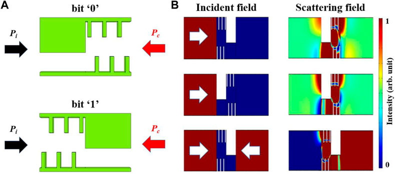
FIGURE 3. (A) Schematic diagram of the composite structure, which can be acted as bits ‘0’ and ‘1’ by using forward and backward placements, respectively. The black and red arrows present the input wave Pi and control wave Pc. (B) The incident and scattering fields of bits ‘0’ and ‘1’ for one side incidence and both sides incidence. The white arrows indicate the incident directions, and the operating frequency is 3,430 Hz.
4 Switchable projection displays
Given the scattering feature of the composite structure, as shown in Figure 4A, we construct three acoustic projection devices with different coding sequences. The metasurface is composed of 24 × 32 coding bits, where the expected image regions are filled with bit ‘1’ and other regions are filled with bit ‘0’. To avoid the coupling actions between two coding bits, the distance between two adjacent coding bits is set as 2W. In addition, to observe the scattering fields conveniently, background pressure field is adopted in the incident field, and the plane acoustic waves are generated with a working frequency of 3,430 Hz. We define input wave Pi incidence as ‘Off state’ and input wave Pi and control wave Pc incidence simultaneously as ‘On state’. For ‘On state’, as illustrated in Figure 4B, three different characters (‘N’, ‘U’, ‘C’) are projected clearly in the scattering fields of three proposed devices owing to the extremely asymmetric intensity responses between bits ‘0’ and ‘1’ in this case. For ‘Off state’, as shown in Figure 4C, the scattering field is a uniform field, and no obvious projection images are able to be observed in this case due to the identical intensity responses between bits ‘0’ and ‘1’. Therefore, arbitrary image can be projected by adopting corresponding coding sequences, and the ‘On/Off states’ are capable of switching by control wave Pc.
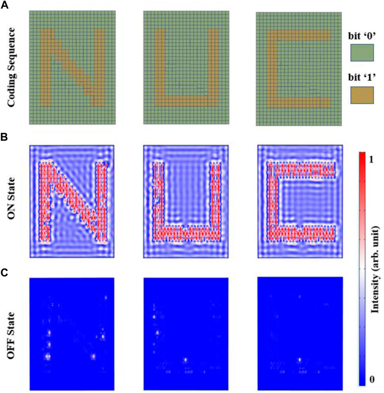
FIGURE 4. (A) Schematic diagrams of coding sequences adopted in projection acoustic devices for ‘N’, ‘U’, ‘C’. The dark green region and dark yellow region represent bit ‘0’ and bit ‘1’, respectively. Acoustic scattering intensity fields of the projection devices with (B) input wave Pi incidence and (C) input wave Pi and control wave Pc incidence simultaneously.
5 Conclusion
An approach is exhibited in this work for switchable acoustic projection displays by using two identical coding units (bits ‘0’ and ‘1’) with different placements. To obtain desirable scattering coefficients for acoustic waves, an AR (a perforated plate) and a PR (a coiling-up cavity with six interdigital rigid walls) are constructed to decouple the phase and amplitude modulations. The composite structure composed of AR and PR shows an extremely asymmetric scattering feature when two coherent acoustic waves incident simultaneously. The required projection can be displayed as long as the expected image regions are filled with bit ‘1’ and other regions are filled with bit ‘0’ due to the coherent superposition. As examples, three distinct characters (‘N’, ‘U’, ‘C’) are projected clearly by adopting three different coding sequences, and the projected images are able to be switched from ‘Off state’ to ‘On state’ accordingly by switching control wave Pc, confirming the feasibility of our approach. Given the advantages of simplified and passive design, the acoustic projection device proposed in our work may have numerous acoustic related engineering applications.
Data availability statement
The original contributions presented in the study are included in the article/Supplementary Material, further inquiries can be directed to the corresponding author.
Author contributions
JH conceived the presented idea. RW performed the calculations and simulations and drafted the manuscript. All authors discussed the results and contributed to the final manuscript.
Funding
This work was supported by the Natural Science Foundation of Shanxi Province under Grant 202103021224201.
Conflict of interest
The authors declare that the research was conducted in the absence of any commercial or financial relationships that could be construed as a potential conflict of interest.
Publisher’s note
All claims expressed in this article are solely those of the authors and do not necessarily represent those of their affiliated organizations, or those of the publisher, the editors and the reviewers. Any product that may be evaluated in this article, or claim that may be made by its manufacturer, is not guaranteed or endorsed by the publisher.
References
1. Walter F, Li G, Meier C, Zhang S, Zentgraf T. Ultrathin nonlinear metasurface for optical image encoding. Nano Lett (2017) 17:3171–5. doi:10.1021/acs.nanolett.7b00676
2. Wintz D, Genevet P, Ambrosio A, Woolf A, Capasso F. Holographic metalens for switchable focusing of surface plasmons. Nano Lett (2015) 15:3585–9. doi:10.1021/acs.nanolett.5b01076
3. Wang Q, Zhang X, Plum E, Xu Q, Wei M, Xu Y, et al. Polarization and frequency multiplexed terahertz meta-holography. Adv Opt Mater (2017) 5:1700277. doi:10.1002/adom.201700277
4. Huang YW, Chen WT, Tsai WY, Wu PC, Wang CM, Sun G, et al. Aluminum plasmonic multicolor meta-hologram. Nano Lett (2015) 15:3122–7. doi:10.1021/acs.nanolett.5b00184
5. Ye WM, Zeuner F, Li X, Reineke B, He S, Qiu CW, et al. Spin and wavelength multiplexed nonlinear metasurface holography. Nat Commun (2016) 7:11930. doi:10.1038/ncomms11930
6. Zhang CM, Yue FY, Wen DD, Chen M, Zhang ZR, Wang W, et al. Multichannel metasurface for simultaneous control of holograms and twisted light beams. ACS Photon (2017) 4:1906–12. doi:10.1021/acsphotonics.7b00587
7. Li JX, Kamin S, Zheng GX, Neubrech F, Zhang S, Liu N. Addressable metasurfaces for dynamic holography and optical information encryption. Sci Adv (2018) 4:eaar6768. doi:10.1126/sciadv.aar6768
8. Li LL, Cui TJ, Ji W, Liu S, Ding J, Wan X, et al. Electromagnetic reprogrammable coding-metasurface holograms. Nat Commun (2017) 8:197. doi:10.1038/s41467-017-00164-9
9. Zang XF, Dong F, Yue F, Zhang C, Xu L, Song Z, et al. Polarization encoded color image embedded in a dielectric metasurface. Adv Mater (2018) 30:1707499. doi:10.1002/adma.201707499
10. Zhang XH, Pu MB, Li X, Gao P, Ma XL, Wang CT, et al. Helicity multiplexed spin-orbit interaction in metasurface for colorized and encrypted holographic display. Ann Phys (2017) 529:1700248. doi:10.1002/andp.201700248
11. Song GY, Cheng Q, Cui TJ, Jing Y. Acoustic planar surface retroreflector. Phys Rev Mater (2018) 2:065201. doi:10.1103/physrevmaterials.2.065201
12. Tang S, Wu J-L, Lü C, Song J, Jiang Y. Functional acoustic metamaterial using shortcut to adiabatic passage in acoustic waveguide couplers. Phys Rev Appl (2022) 18:014038. doi:10.1103/physrevapplied.18.014038
13. Xie Y, Wang W, Chen H, Konneker A, Popa B-I, Cummer SA. Wavefront modulation and subwavelength diffractive acoustics with an acoustic metasurface. Nat Commun (2014) 5:5553. doi:10.1038/ncomms6553
14. Tang S, Ren B, Feng Y, Song J, Jiang Y. Asymmetric acoustic beam shaping based on monolayer binary metasurfaces. Appl Phys Express (2021) 14:085504. doi:10.35848/1882-0786/ac15bf
15. Ge Y, S un HX, Liu C, Qian J, Yuan SQ, Xia JP, et al. Acoustic focusing by an array of heat sources in air. Appl Phys Express (2016) 9:066701. doi:10.7567/apex.9.066701
16. Liu C, Xia JP, Sun HX, Yuan SQ. Thermoacoustic focusing lens by symmetric Airy beams with phase manipulations. J Phys D: Appl Phys (2017) 50:505101. doi:10.1088/1361-6463/aa964a
17. Tang S, Wu J-L, Lü C, Wang X, Song J, Jiang Y. Acoustic wavelength-selected metamaterials designed by reversed fractional stimulated Raman adiabatic passage. Phys Rev B (2022) 105:104107. doi:10.1103/physrevb.105.104107
18. Wang WQ, Xie YB, Konneker A, Popa B-I, Cummer SA. Design and demonstration of broadband thin planar diffractive acoustic lenses. Appl Phys Lett (2014) 105:101904. doi:10.1063/1.4895619
19. Tang S, Lü C, Wu J-L, Song J, Jiang Y. Wavelength-selected bifunctional beam shaping for transmitted acoustic waves via coding metasurface. Appl Acoust (2022) 194:108786. doi:10.1016/j.apacoust.2022.108786
20. Jiang X, Li Y, Liang B, Cheng J-c., Zhang L. Convert acoustic resonances to orbital angular momentum. Phys Rev Lett (2016) 117:034301. doi:10.1103/physrevlett.117.034301
21. Tang S, Wu J-L, Lü C, Yao J, Wang X, Song J, et al. One-way acoustic beam splitting in spatial four-waveguide couplers designed by adiabatic passage. New J Phys (2023) 25:033032. doi:10.1088/1367-2630/acc609
22. Tang S, Ren B, Feng Y, Song J, Jiang Y. The generation of acoustic Airy beam with selective band based on binary metasurfaces: Customized on demand. Appl Phys Lett (2021) 119:071907. doi:10.1063/5.0060032
23. Zhang Y, Xie B, Liu W, Cheng H, Chen S, Tian J. Anomalous reflection and vortex beam generation by multibit coding acoustic metasurfaces. Appl Phys Lett (2019) 114:091905. doi:10.1063/1.5087636
24. Xie B, Cheng H, Tang K, Liu Z, Chen S, Tian J. Multiband asymmetric transmission of airborne sound by coded metasurfaces. Phy Rev Appl (2017) 7:024010. doi:10.1103/physrevapplied.7.024010
25. Ghaffarivardavagh R, Nikolajczyk J, Glynn Holt R, Anderson S, Zhang X. Horn-like space-coiling metamaterials toward simultaneous phase and amplitude modulation. Nat Commun (2018) 9:1349. doi:10.1038/s41467-018-03839-z
26. Zhu X, Li K, Zhang P, Zhu J, Zhang J, Tian C, et al. Implementation of dispersion-free slow acoustic wave propagation and phase engineering with helical-structured metamaterials. Nat Commun (2016) 7:11731. doi:10.1038/ncomms11731
27. Xie B, Tang K, Cheng H, Liu Z, Chen S, Tian J. Coding acoustic metasurfaces. Adv Mater (2017) 29:1603507. doi:10.1002/adma.201603507
28. Li K, Liang B, Yang J, Yang J, Cheng JC. Broadband transmission-type coding metamaterial for wavefront manipulation for airborne sound. Appl Phys Express (2018) 11:077301. doi:10.7567/apex.11.077301
29. Chen DC, Zhu X-F, Wu D-J, Liu X-J. Broadband Airy-like beams by coded acoustic metasurfaces. Appl Phys Lett (2019) 114:053504. doi:10.1063/1.5080202
Keywords: composite structure, coiling-up cavity, switchable projection, coherent superposition, artificial structure
Citation: Han J and Wang R (2023) Switchable acoustic projection displays based on coding composite structures. Front. Phys. 11:1191108. doi: 10.3389/fphy.2023.1191108
Received: 21 March 2023; Accepted: 13 April 2023;
Published: 26 April 2023.
Edited by:
Feng Zhou, Toyota Research Institute of North America, United StatesReviewed by:
Yabin Jin, Tongji University, ChinaYongyuan Jiang, Harbin Institute of Technology, China
Copyright © 2023 Han and Wang. This is an open-access article distributed under the terms of the Creative Commons Attribution License (CC BY). The use, distribution or reproduction in other forums is permitted, provided the original author(s) and the copyright owner(s) are credited and that the original publication in this journal is cited, in accordance with accepted academic practice. No use, distribution or reproduction is permitted which does not comply with these terms.
*Correspondence: Rui Wang, d2FuZ3J1aW51Y0AxNjMuY29t