- 1College of Electrical and Information Engineering, Hunan Institute of Engineering, Xiangtan, China
- 2School of Computer and Communication Engineering, Changsha University of Science and Technology, Changsha, China
Compared to voltage mode circuits, current mode circuits have advantages such as large dynamic range, fast speed, wide frequency band, and good linearity. In recent years, the development of call flow modeling technology has been rapid and has become an important foundation for analog integrated circuits. In this paper, a current mode chaotic oscillation circuit based on current differential transconductance amplifier (CDTA) is proposed. This proposed circuit fully utilizes the advantages of current differential transconductance amplifier: a current input and output device with a large dynamic range, virtual ground at the input, extremely low input impedance, and high output impedance. The linear and non-linear parts of the proposed circuit operate in current mode, enabling a true current mode multi scroll chaotic circuit. Pspice simulation results show that the current mode chaotic circuit proposed can generate multi scroll chaotic attractors.
1 Introduction
In the past 40 years, due to the unique advantages of chaotic systems such as extreme sensitivity to initial values and parameters, ergodicity, and pseudorandomness, chaos has paid more attention to the combination of theory and practical applications, and has been widely used in fields such as secure communication [1–3], image encryption [4–8], random number generators [9–11], memristors [12–17], neural networks [18–25], and chaotic synchronization control [26–30].
The chaotic signal generated by chaotic oscillation circuits or chaotic systems is the core part of the entire chaotic communication system and has always been a research hotspot in the field of chaos [31–38]. How to generate multi scroll chaotic attractors with more complex topological structures has been widely concerned [39–41]. At present, most of the multi scroll chaotic oscillators are implemented by operational amplifiers [42–44], transconductance operational amplifiers (OTA) [45], current feedback operational amplifiers (CFOA) [46, 47] and second-generation current conveyers (CCII) [48–50]. The principles and methods for designing multi scroll chaotic oscillators based on operational amplifiers, CFOAs, and OTAs are summarized in [45]. In [46], a multi scroll chaotic oscillator was implemented using CFOA, and 3–10 scrolls from 1 kHz to 100 kHz were generated in experiments. In [49], the authors proposed a simple multi scroll chaotic oscillator implemented using a positive CCII and a negative CCII-. Circuit simulation shows that the chaotic electronic oscillator can generate more scroll chaotic attractors with higher frequencies. Because the operational amplifier belongs to the traditional voltage mode (voltage input, voltage output) circuit, the chaotic oscillator based on the operational amplifier has the problem of narrow bandwidth; OTA, CFOA and CCII belong to the voltage and current mixed mode devices, The following problems exist in the chaotic oscillator based on OTA, CFOA and CCII:
1) Since the chaotic oscillator composed of OTA, CFOA and CCII still works in voltage mode, the output impedance is very high and changes with frequency.
2) Due to the large parasitic parameters at the input terminals of OTA, CFOA and CCII, the frequency bandwidth of the chaotic oscillator based on OTA, CFOA and CCII is not large.
Currently, analog integrated circuit designs mostly use voltage mode circuit designs [51–53]. With the development and breakthrough of various new technologies represented by the PCB process, traditional voltage mode circuits are no longer suitable for low power supply voltage design requirements due to their high impedance, high voltage gain, and high signal swing characteristics, while current mode circuits have attracted widespread interest due to their low impedance, zero or even negative voltage gain, and broadband characteristics [54–59]. Current differential transconductance amplifier (CDTA) is a current input and output device, characterized by extremely low input impedance, high output impedance, and large dynamic range. Compared to OTA, CFOA, and CCII, it is a true current mode device [60–63]. Two new implementations of current mode quadrature oscillators using CDTA as active components are proposed in [64]. The proposed circuit uses two grounded capacitors to achieve current controllability of the oscillation frequency. In [65], a floating decreasing and increasing memristor simulator using OTA, CDTA, and two grounded capacitors is used. Then, the proposed memristor simulator is used in the design of chaotic oscillators and adaptive learning circuits. Simulation results of a chaotic oscillator and an adaptive learning circuit verify the effectiveness of the proposed design. When it is used to form a current mode chaotic circuit, the input and output impedances have nothing to do with frequency, which can generate a larger number of chaotic attractors at high frequencies. In addition, since the input end of the CDTA is a virtual ground, the frequency parasitic parameters are small and the bandwidth is large.
In this paper, a current mode chaotic circuit based on CDTA is proposed, which can generate multi scroll chaotic attractor current signals, promote the practical application of chaos communication, chaotic neural network and other fields.
This paper is organized as follows. In Section 2, the CDTA is studied by theoretical analyses and Pspice simulation. In Section 3, the proposed current mode basic operation modules of chaotic circuit based on CDTA is studied by theoretical analyses and Pspice simulation. In Section 4, we draw our conclusions.
2 The CDTA
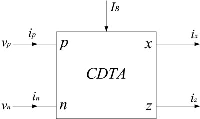
The CDTA is a current-input, current-output current mode device with a large dynamic range. When forming a current mode circuit, it has both low input impedance and high output impedance characteristics. Figure 1 is the circuit symbol of CDTA.
Among them, p and n are the differential current input terminals, z is the auxiliary terminal, the current at the z terminal is the difference between the input currents of p and n, the x terminal is the current output terminal, and IB is the external bias current. The port characteristics of CDTA are as follows:
where
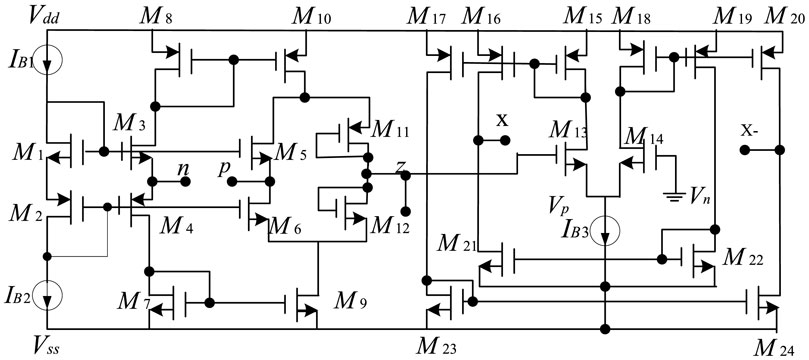
A CMOS CDTA circuit is designed, and the circuit schematic diagram is shown in Figure 2. Multiple x+ and x-ports can be expanded as needed. The transistor constitutes the current differential part, so that the z current of the auxiliary terminal is equal to the current difference between the p and n terminals. After an impedance is connected to the auxiliary terminal, the voltage vz of the z terminal is obtained to realize the transconductance. The amplifying unit converts vz into the current output of the x terminal.
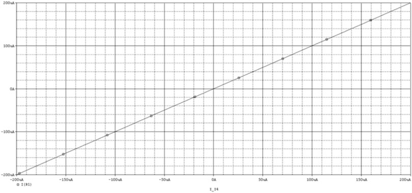
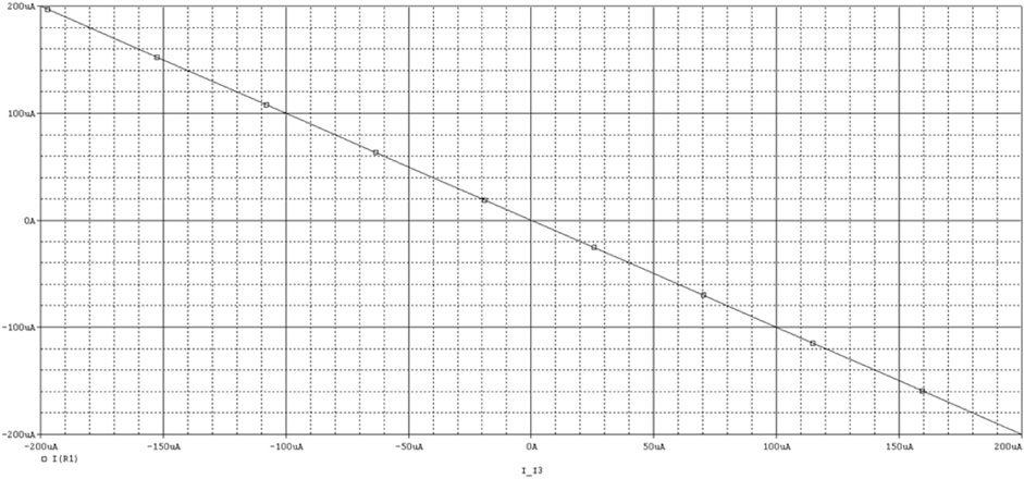
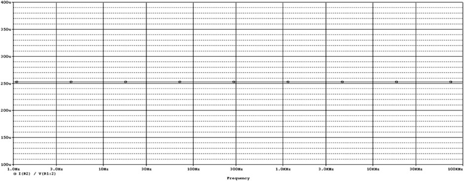
The Pspice simulation results of CDTA are as follows: Power supply voltage VDD = 2.5V, VSS = −2.5 V, external control current Ib = 200 uA. If only Ip is scanned when In = 0A is given, the relationship curve between Iz and Ip can be obtained as shown in Figure 3; If only In is scanned when Ip = 0A is given, the relationship curve between Iz and In can be obtained as shown in Figure 4. According to these two curves, it is not difficult to see that Iz is a difference relationship with Ip and In. When Ip = 1A, In = −1A, Ib = 200 uA, the transconductance gain of CDTA gm = Ix/Vz = Ix/(Ip-In) can be obtained, and the simulation results are shown in Figure 5.
3 The proposed current mode basic operation modules of chaotic circuit based on CDTA
The basic operation modules of the chaotic system (such as addition and subtraction, integration, etc.) and non-linear function generating circuits (such as step function, saturation function, etc.) can be easily realized by CDTA.
3.1 Integrator module
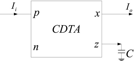
It can be seen from Equation 1 and Figure 1 that the input voltage of CDTA is zero and the input impedance is zero (the input impedance of the actual circuit is very small). In addition, the output impedance is also very high. When CDTA is used to form a current mode integrator, the input and output impedance characteristics are not destroyed. Figure 6 shows the current mode integrator composed of CDTA and capacitor, the output current expression is:
Since the capacitor is not connected to the input and output terminals of CDTA, but is connected to the auxiliary terminal z of CDTA, the CDTA-C current mode integrator has very low input impedance and high output impedance, and has nothing to do with frequency, The input impedance of the CDTA-C current mode integrator is ideally 0, and the output impedance is the output impedance of CDTA (usually MΩ level). When implementing a chaotic circuit, the system parameters are independent of frequency, so that it can output chaos signal with a large bandwidth.
3.2 Adder module
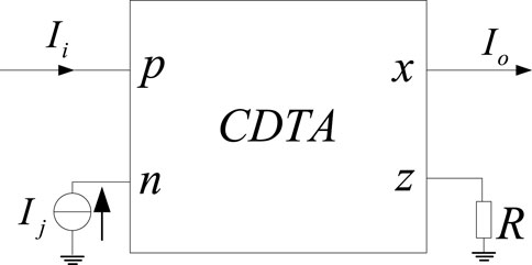
Figure 7 shows the current mode addition and subtraction operation module composed of CDTA. Since CDTA has p and n as differential current input terminals, current mode addition and subtraction can be easily realized. The output current expression is:
3.3 Step function module
The step function can be approximated as a saturation function with a sufficiently large slope. The basic unit circuit of the step function using CDTA is shown in Figure 8. The saturation current that the CDTA can achieve for a given supply voltage is denoted by
It can be seen from the above that the non-linear function generation circuit composed of CDTA compares the state variable current with the comparison current, and outputs the current saturation function. It can be seen that when CDTA is used to form a chaotic circuit, whether it is a linear circuit part or a non-linear circuit, all of them work in the current mode, which can realize the real current mode chaotic circuit.
In addition, due to the grounding of the input terminal (generally virtual grounding when the circuit is implemented), the parasitic parameters are small, the frequency characteristics are good, and the operating frequency bandwidth is wide.
Therefore, compared with operational amplifiers, OTA, CFOA and CCII, CDTA is more suitable for implementing current mode chaotic oscillator circuits. However, so far, there is no report on the use of CDTA to form a chaotic oscillator circuit.
3.4 The proposed CDTA-based current mode multi scroll Jerk chaotic oscillator circuit
Due to the simplicity and good recursion characteristics of the Jerk system, it has become a typical example for the study of multi scroll chaotic systems. This design adopts the classic Jerk system, and its dimensionless state equation is:
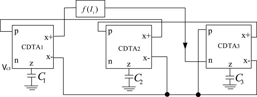
The proposed CDTA-based current mode multi scroll Jerk chaotic oscillator circuit is shown in Figure 9.
The main circuit of the chaotic oscillation circuit is composed of three CDTAs and three programmable equivalent capacitances CEQ, and the circuit structure is very simple. Its non-linear function adopts a step function, and the step function generating circuit is shown in Figure 8. By connecting several basic units in parallel, the step function sequence can be obtained.
It can be seen from Figures 8, 9 that the non-linear function generating circuit and the main circuit of the chaotic circuit are both current mode circuits implemented by CDTA, with good high frequency characteristics and large dynamic range, and can be designed to generate more scrolls chaotic system. And because the capacitor is connected to the auxiliary z terminal, the input and output impedances are independent of the frequency, so the chaotic system equation will not change with the frequency.
Derive the dynamic equation of the multi scroll chaotic oscillator circuit corresponding to the circuit diagram shown in Figure 9.
This is a set of third-order non-linear autonomous ordinary differential equations with the currents at the x + ports of the output terminals of CDTA1, CDTA2, and CDTA3 respectively, and as the three state variables, and the non-linear functions
3.5 Design of even-numbered scroll Jerk system
The non-linear function adopts step function:
Where, N, M = 1,2,3,4, etc. Especially when N = M, there is
Where A = A1 is the saturation value of the saturation function, and the number of scrolls can be generated is 2 *N+2. When N = 0,
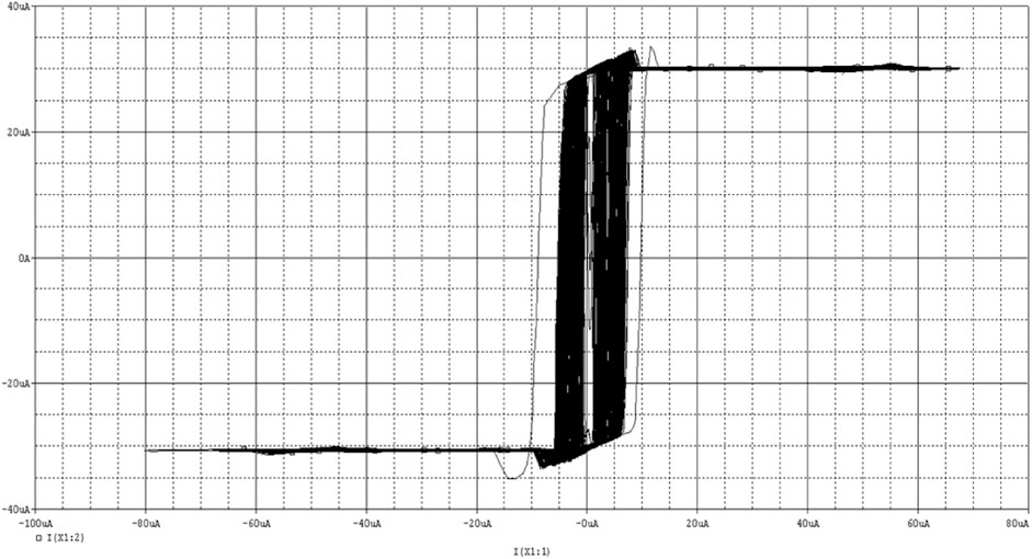
From the above figures, we can get A = A1 = 30uA, take N = 1, then we can get 4-step waves, and the simulation is shown in Figure 11. It can be seen that the 4-step function can be achieved, which can generate four saddle focal equilibrium points with two indicators, and can achieve four scrolls.
3.6 Design of odd-numbered scroll Jerk system
Using Eq. (4), an odd number of scrolls can be generated, and the number of scrolls is N + M+2. Now take the generation of three scroll numbers as an example. Let N = 1, M = 0, and the scroll number be N + M+2 = 1 + 0+2 = 3. Then Eq. (4) becomes Eq. (6)
From this, 3-step waves can be obtained, and the simulation is shown in Figure 12. It can be seen that the 3-step function can be achieved, which can generate three saddle focal equilibrium points with two indicators, and can achieve three scrolls.
3.7 Simulation of multi scroll chaotic circuit
According to the expression Eq. (4) of the non-linear function f(x), when N and M take different values, different step waves will be generated, which will affect the number of scroll generated. When N = M and N = 0, two scroll attractors are generated, as shown in Figure 13.

FIGURE 13. Two scroll chaotic attractor. (A) x-y phase diagram of chaotic attractor. (B) x-z phase diagram of chaotic attractor.
When N = M, N = 1, four scroll attractors are generated, as shown in Figure 14.
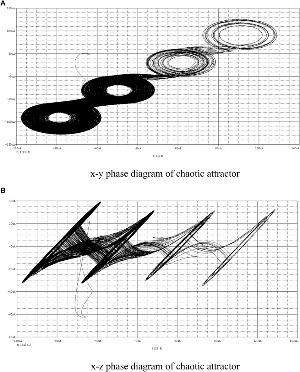
FIGURE 14. Four scroll chaotic attractor. (A) x-y phase diagram of chaotic attractor. (B) x-z phase diagram of chaotic attractor.
When N = 1, M = 0, three scroll attractors are generated, as shown in Figure 15.
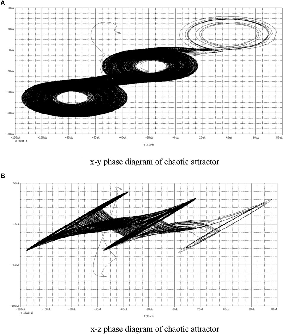
FIGURE 15. Three scroll chaotic attractor. (A) x-y phase diagram of chaotic attractor. (B) x-z phase diagram of chaotic attractor.
As shown in these figures, the proposed CDTA-based current mode multi scroll Jerk chaotic oscillator circuit can display a theoretical number of scrolls in both the x-y and x-z directions. The experimental results are consistent with the theoretical results.
4 Conclusion
The circuit structure of the multi scroll chaotic oscillator based on CDTA proposed in this paper is simple, the main circuit does not contain passive resistance elements, has low input impedance, high output impedance, and the input and output impedance are independent of frequency, and the dynamic range is large, so that the chaotic oscillator can generate more scrolls, and the signal is not distorted.
Data availability statement
The original contributions presented in the study are included in the article/supplementary material, further inquiries can be directed to the corresponding authors.
Author contributions
YL: Conceptualization, Methodology, Visualization, Project administration, Supervision, Writing–Review and Editing. JG: Methodology, Investigation, Formal analysis, Supervision. FY: Methodology, Investigation, Formal analysis, Writing–Original Draft. YH: Investigation, Formal analysis, Supervision. All authors contributed to the article and approved the submitted version.
Funding
This work is supported by the Scientific Research Fund of Hunan Provincial Education Department under Grants 20k036, 21B0345 and 19C0083, and by the Hunan Provincial Natural Science Foundation of China under Grant 2022JJ30624, and by the Postgraduate Training Innovation Base Construction Project of Hunan Province under Grant 2020-172-48.
Conflict of interest
The authors declare that the research was conducted in the absence of any commercial or financial relationships that could be construed as a potential conflict of interest.
Publisher’s note
All claims expressed in this article are solely those of the authors and do not necessarily represent those of their affiliated organizations, or those of the publisher, the editors and the reviewers. Any product that may be evaluated in this article, or claim that may be made by its manufacturer, is not guaranteed or endorsed by the publisher.
References
1. Yu F, Yu Q, Chen H, Kong X, Mokbel AAM, Cai S, et al. Dynamic analysis and audio encryption application in IoT of a multi scroll fractional-order memristive Hopfield neural network. Fractal and Fractional (2022) 6(7):370. doi:10.3390/fractalfract6070370
2. Zhou L, Tan F. A chaotic secure communication scheme based on synchronization of double-layered and multiple complex networks. Nonlinear Dyn (2019) 96(2):869–83. doi:10.1007/s11071-019-04828-7
3. Gokyildirim A, Kocamaz UE, Uyaroglu Y, Calgan H. A novel five-term 3D chaotic system with cubic nonlinearity and its microcontroller-based secure communication implementation. AEU-International J Elect Commun (2023) 160:154497. doi:10.1016/j.aeue.2022.154497
4. Yu F, Xu S, Xiao X, Yao W, Huang Y, Cai S, et al. Dynamics analysis, FPGA realization and image encryption application of a 5D memristive exponential hyperchaotic system. Integration (2023) 90:58–70. doi:10.1016/j.vlsi.2023.01.006
5. Zhu Y, Wang C, Sun J, Yu F. A chaotic image encryption method based on the artificial fish swarms algorithm and the DNA coding. Mathematics (2023) 11:767. doi:10.3390/math11030767
6. Yu F, Kong X, Mokbel AAM, Yao W, Cai S. Complex dynamics, hardware implementation and image encryption application of multiscroll memeristive hopfield neural network with a novel local active memeristor. IEEE Trans Circuits Syst Express Briefs (2023) 70(1):326–30. doi:10.1109/tcsii.2022.3218468
7. Xie Z, Sun J, Tang Y, Tang X, Simpson O, Sun Y. A K-svd based compressive sensing method for visual chaotic image encryption. Mathematics (2023) 11(7):1658. doi:10.3390/math11071658
8. Gao X, Sun B, Cao Y, Banerjee S, Mou J. A color image encryption algorithm based on hyperchaotic map and DNA mutation. Chin Phys B (2023) 32:030501. doi:10.1088/1674-1056/ac8cdf
9. Yu F, Zhang Z, Shen H, Huang Y, Cai S, Jin J, et al. Design and FPGA implementation of a pseudo-random number generator based on a Hopfield neural network under electromagnetic radiation. Front Phys (2021) 9:690651. doi:10.3389/fphy.2021.690651
10. Yang Z, Liu Y, Wu Y, Qi Y, Ren F. A high speed pseudo-random bit generator driven by 2D-discrete hyperchaos. Chaos, Solitons & Fractals (2023) 167:113039. doi:10.1016/j.chaos.2022.113039
11. Yu F, Zhang Z, Shen H, Huang Y, Cai S, Du S. FPGA implementation and image encryption application of a new PRNG based on a memristive Hopfield neural network with a special activation gradient. Chin Phys B (2022) 31(2):020505. doi:10.1088/1674-1056/ac3cb2
12. Min F, Xue L. Routes toward chaos in a memristor-based Shinriki circuit. Chaos (2023) 33(2):023122. doi:10.1063/5.0126900
13. Lin H, Wang C, Xu C, Zhang X, Iu HHC. A memristive synapse control method to generate diversified multi-structure chaotic attractors. IEEE Trans Computer-Aided Des Integrated Circuits Syst (2022) 42:942–55. doi:10.1109/TCAD.2022.3186516
14. Min F, Cheng Y, Lu L, Li X. Extreme multistability and antimonotonicity in a Shinriki oscillator with two flux-controlled memristors. Int J Bifurcation Chaos (2021) 31(11):2150167. doi:10.1142/s0218127421501674
15. Chen Y, Mou J, Jahanshahi H, Wang Z, Cao Y. A new mix chaotic circuit based on memristor-memcapacitor. The Eur Phys J Plus (2023) 138(1):78. doi:10.1140/epjp/s13360-023-03699-7
16. Ma M, Lu Y, Li Z, Sun Y, Wang C. Multistability and phase synchronization of rulkov neurons coupled with a locally active discrete memristor. Fractal and Fractional (2023) 7(1):82. doi:10.3390/fractalfract7010082
17. Yu F, Zhang W, Xiao X, Yao W, Cai S, Zhang J, et al. Dynamic analysis and FPGA implementation of a new, simple 5D memristive hyperchaotic Sprott-C system. Mathematics (2023) 11(3):701. doi:10.3390/math11030701
18. Lin H, Wang C, Yu F, Sun J, Du S, Deng Z, et al. A review of chaotic systems based on memristive hopfield neural networks. Mathematics (2023) 11(6):1369. doi:10.3390/math11061369
19. Xu Q, Chen X, Chen B, Wu H, Li Z, Han B. Dynamical analysis of an improved FitzHugh-Nagumo neuron model with multiplier-free implementation. Nonlinear Dyn (2023) 111(9):8737–49. doi:10.1007/s11071-023-08274-4
20. Yu F, Shen H, Yu Q, Kong X, Sharma PK, Cai S. Privacy protection of medical data based on multi scroll memristive hopfield neural network. IEEE Trans Netw Sci Eng (2023) 10(2):845–58. doi:10.1109/tnse.2022.3223930
21. Wan Q, Li F, Chen S, Yang Q. Symmetric multi-scroll attractors in magnetized Hopfield neural network under pulse controlled memristor and pulse current stimulation. Chaos, Solitons & Fractals (2023) 169:113259. doi:10.1016/j.chaos.2023.113259
22. Xu Q, Tong L, Ding S, Wu H, Huang L, Chen B. Extreme multistability and phase synchronization in a heterogeneous bi-neuron Rulkov network with memristive electromagnetic induction. Cogn Neurodynamics (2022). doi:10.1007/s11571-022-09866-3
23. Yu F, Liu L, Xiao L, Li K, Cai S. A robust and fixed-time zeroing neural dynamics for computing time-variant nonlinear equation using a novel nonlinear activation function. Neurocomputing (2019) 350:108–16. doi:10.1016/j.neucom.2019.03.053
24. Jin J, Zhu J, Zhao L, Chen L, Chen L, Gong J. A robust predefined-time convergence zeroing neural network for dynamic matrix inversion. IEEE Trans Cybernetics (2022) 53:3887–900. doi:10.1109/TCYB.2022.3179312
25. Sun J, Wang Y, Liu P, Wen S. Memristor-based neural network circuit with multimode generalization and differentiation on pavlov associative memory. IEEE Trans Cybernetics (2023) 53(5):3351–62. doi:10.1109/tcyb.2022.3200751
26. Chen W, Jin J, Chen C, Fei Y, Wang C. A disturbance suppression zeroing neural network for robust synchronization of chaotic systems and its FPGA implementation. Int J Bifurcation Chaos (2022) 32(14):2250210. doi:10.1142/s0218127422502108
27. Yao W, Wang CH, Sun YC, Zhou C. Robust multimode function synchronization of memristive neural networks with parameter perturbations and time-varying delays. IEEE Trans Syst Man, Cybernetics: Syst (2022) 52(1):260–74. doi:10.1109/tsmc.2020.2997930
28. Ma M, Xie XH, Yang Y, Li ZJ, Sun YC. Synchronization coexistence in a rulkov neural network based on locally active discrete memristor. Chin Phys. B (2023) 32:058701. doi:10.1088/1674-1056/acb9f7
29. Tan F, Zhou L, Lu J, Quan H, Liu K. Adaptive quantitative control for finite time synchronization among multiplex switched nonlinear coupling complex networks. Eur J Control (2023) 70:100764. doi:10.1016/j.ejcon.2022.100764
30. Yao W, Wang CH, Sun YC, Gong SQ, Lin HR. Event-triggered control for robust exponential synchronization of inertial memristive neural networks under parameter disturbance. Neural Networks (2023) 16:467–80. doi:10.1016/j.neunet.2023.04.024
31. Wang N, Xu D, Kuznetsov NV, Han B, Chen M, Xu Q. Experimental observation of hidden Chua’s attractor. Chaos, Solitons and Fractals (2023) 170:113427. doi:10.1016/j.chaos.2023.113427
32. Sun J, Wang Y, Liu P, Wen S. Memristor-based circuit design of PAD emotional space and its application in mood congruity. IEEE Internet Things J (2023) 1. doi:10.1109/JIOT.2023.3267778
33. Deng Z, Wang C, Lin H, Sun Y. A memristive spiking neural network circuit with selective supervised attention algorithm. IEEE Trans Computer-Aided Des Integrated Circuits Syst (2022) 1. doi:10.1109/TCAD.2022.3228896
34. Shen H, Yu F, Kong X, Mokbel AAM, Wang C, Cai S. Dynamics study on the effect of memristive autapse distribution on Hopfield neural network. Chaos (2022) 32(8):083133. doi:10.1063/5.0099466
35. Liao M, Wang C, Sun Y, Lin H, Xu C. Memristor-based affective associative memory neural network circuit with emotional gradual processes. Neural Comput Appl (2022) 34(16):13667–82. doi:10.1007/s00521-022-07170-z
36. Jin J, Chen W, Chen C, Chen L, Tang Z, Chen L, et al. A predefined fixed-time convergence ZNN and its applications to time-varying quadratic programming solving and dual-arm manipulator cooperative trajectory tracking. IEEE Trans Ind Inform (2022) 1–12. doi:10.1109/TII.2022.3220873
37. Shen H, Yu F, Wang C, Sun J, Cai S. Firing mechanism based on single memristive neuron and double memristive coupled neurons. Nonlinear Dyn (2022) 110:3807–22. doi:10.1007/s11071-022-07812-w
38. Jin J, Chen W, Ouyang A, Liu H. Towards fuzzy activation function activated zeroing neural network for currents computing. IEEE Trans Circuits Syst Express Briefs (2023) 1. doi:10.1109/TCSII.2023.3269060
39. Lin H, Wang C, Sun Y, Wang T. Generating n-scroll chaotic attractors from a memristor-based magnetized hopfield neural network. IEEE Trans Circuits Syst Express Briefs (2023) 70(1):311–5. doi:10.1109/tcsii.2022.3212394
40. Ben Slimane N, Bouallegue K, Machhout M. Designing a multi scroll chaotic system by operating Logistic map with fractal process. Nonlinear Dyn (2017) 88:1655–75. doi:10.1007/s11071-017-3337-0
41. Yu F, Shen H, Zhang Z, Huang Y, Cai S, Du S. A new multi scroll Chua’s circuit with composite hyperbolic tangent-cubic nonlinearity: Complex dynamics, Hardware implementation and Image encryption application. Integration (2021) 81:71–83. doi:10.1016/j.vlsi.2021.05.011
42. Chen D, Sun Z, Ma X, Chen L. Circuit implementation and model of a new multi-scroll chaotic system. Int J Circuit Theor Appl (2014) 42(4):407–24. doi:10.1002/cta.1860
43. Chao-Xia Z, Si-Min Y. Design and implementation of a novel multi scroll chaotic system. Chin Phys B (2009) 18(1):119–29. doi:10.1088/1674-1056/18/1/019
44. Chen L, Pan W, Wu R, Wang K, He Y. Generation and circuit implementation of fractional-order multi scroll attractors. Chaos, Solitons & Fractals (2016) 85:22–31. doi:10.1016/j.chaos.2016.01.016
45. Munoz-Pacheco JM, Campos-Lopez W, Tlelo-Cuautle E, Sanchez-Lo C. OpAmp-CFOA-and OTA-based configurations to design multi scroll chaotic oscillators. Trends Appl Sci Res (2012) 7(2):168–74. doi:10.3923/tasr.2012.168.174
46. Munoz-Pacheco JM, Tlelo-Cuautle E, Toxqui-Toxqui I, Sánchez-López C, Trejo-Guerra R. Frequency limitations in generating multi scroll chaotic attractors using CFOAs. Int J Elect (2014) 101(11):1559–69. doi:10.1080/00207217.2014.880999
47. Wang CH, Yin JW, Lin Y. Design and realization of grid multi scroll chaotic circuit based on current conveyers. Acta Phys Sin (2012) 61(21):210507. doi:10.7498/aps.61.210507
48. Zhang X, Wang C. A novel multi-attractor period multi scroll chaotic integrated circuit based on CMOS wide adjustable CCCII. IEEE Access (2019) 7:16336–50. doi:10.1109/access.2019.2894853
49. Lin Y, Wang CH, Xu H. Grid multi scroll chaotic attractors in hybrid image encryption algorithm based on current conveyor. Acta Phys Sin (2012) 61(24):240503. doi:10.7498/aps.61.240503
50. Zuo T, Sun K-H, Ai X-X, Wang H-H. Grid multi scroll chaotic circuit based on the second generation current conveyers. Acta Phys Sin (2014) 63(8):080501. doi:10.7498/aps.63.080501
51. Yu F. A low-voltage and low-power 3-GHz CMOS LC VCO for S-band wireless applications. Wireless Personal Communications (2014) 78(2):905–14. doi:10.1007/s11277-014-1791-2
52. Yu F, Tang Q, Wang W, Wu H. A 2.7 GHz low-phase-noise LC-QVCO using the gate-modulated coupling technique. Wireless Personal Commun (2016) 86:671–81. doi:10.1007/s11277-015-2951-8
53. Yu F, Gao L, Liu L, Qian S, Cai S, Song Y. A 1 V, 0.53 ns, 59 μW current comparator using standard 0.18 μm CMOS technology. Wireless Personal Commun (2020) 111(2):843–51. doi:10.1007/s11277-019-06888-9
54. Chen JH, Chau KT, Chan CC. Analysis of chaos in current-mode-controlled DC drive systems. IEEE Trans Ind Elect (2000) 47(1):67–76. doi:10.1109/41.824127
55. Chang CY, Zhao X, Yang F, Wu CE. Bifurcation and chaos in high-frequency peak current mode Buck converter. Chin Phys B (2016) 25(7):070504. doi:10.1088/1674-1056/25/7/070504
56. Unuk T, Arslanalp R, Tez S. Design of Current-Mode versatile Multi-Input analog multiplier topology. AEU-International J Elect Commun (2023) 160:154493. doi:10.1016/j.aeue.2022.154493
57. Ahmadi S, Mahmoudi A, Maddipatla D, Bazuin BJ, Azhari SJ, Atashbar MZ. A current mode instrumentation amplifier with high common-mode rejection ratio designed using a novel fully differential second-generation current conveyor. SN Appl Sci (2023) 5(1):34. doi:10.1007/s42452-022-05247-x
58. Lberni A, Marktani MA, Ahaitouf A, Ahaitouf A. An efficient optimisation-based design of current conveyor performances. Int J Comp Aided Eng Tech (2023) 18(1-3):167–80. doi:10.1504/ijcaet.2023.127794
59. Ariando D, Mandal S. A pulsed current-mode class-D low-voltage high-bandwidth power amplifier for portable NMR systems. J Magn Reson (2023) 348:107367. doi:10.1016/j.jmr.2023.107367
60. Keskin AÜ, Biolek D. Current mode quadrature oscillator using current differencing transconductance amplifiers (CDTA). IEE Proceedings-Circuits, Devices Syst (2006) 153(3):214–8. doi:10.1049/ip-cds:20050304
61. Jin J, Wang C. Single CDTA-based current-mode quadrature oscillator. AEU-International J Elect Commun (2012) 66(11):933–6. doi:10.1016/j.aeue.2012.03.018
62. Kacar F, Kuntman HH. A new, improved CMOS realization of CDTA and its filter applications. Turkish J Electr Eng Comp Sci (2011) 19(4):631–42. doi:10.3906/elk-1003-467
63. Jaikla W, Siripruchyanun M, Bajer J, Biolek D. A simple current-mode quadrature oscillator using single CDTA. Radioengineering (2008) 17(4):33–40. doi:10.1070/QE2008v038n12ABEH013799
64. Lahiri A. New current-mode quadrature oscillators using CDTA. IEICE Elect Express (2009) 6(3):135–40. doi:10.1587/elex.6.135
Keywords: current mode, multi scroll, chaotic oscillation, CDTA, chaotic attractors
Citation: Lin Y, Gong J, Yu F and Huang Y (2023) Current mode multi scroll chaotic oscillator based on CDTA. Front. Phys. 11:1202398. doi: 10.3389/fphy.2023.1202398
Received: 08 April 2023; Accepted: 16 May 2023;
Published: 30 May 2023.
Edited by:
Chunbiao Li, Nanjing University of Information Science and Technology, ChinaReviewed by:
Jingru Sun, Hunan University, ChinaJie Jin, Hunan University of Science and Engineering, China
Fuhong Min, Nanjing Normal University, China
Copyright © 2023 Lin, Gong, Yu and Huang. This is an open-access article distributed under the terms of the Creative Commons Attribution License (CC BY). The use, distribution or reproduction in other forums is permitted, provided the original author(s) and the copyright owner(s) are credited and that the original publication in this journal is cited, in accordance with accepted academic practice. No use, distribution or reproduction is permitted which does not comply with these terms.
*Correspondence: Yuan Lin, MTUzMTkwNjc1QHFxLmNvbQ==; Fei Yu, eXVmZWl5ZnlmQGNzdXN0LmVkdS5jbg==
 Yuan Lin
 Junhui Gong1
 Fei Yu