 Kaiming Luo1,2
 Qiang Fu1,2*Yue Zhang1,2Wei Yang1,2
 Su Zhang1,2
 Juntong Zhan1,2Zheng Li3Yi Ma4
 Jin Duan5Huilin Jiang1,2
- 1National and Local Joint Engineering Research Center of Space Optoelectronics Technology, Changchun University of Science and Technology, Changchun, China
- 2College of Opto-Electronic Engineering, Changchun University of Science and Technology, Changchun, China
- 3Chinese People’s Liberation Army 96944 Unit, Beijing, China
- 4First Institute of Oceanography, Ministry of Natural Resources, Qingdao, China
- 5College of Electronic Information Engineering, Changchun University of Science and Technology, Changchun, China
Sea spray particles are a type of non-uniform, non-spherical, non-isotropic, and complex medium, and the study of the transmission characteristics of polarized light in a real sea spray environment can provide reference values in many fields, such as polarization imaging, marine target detection, and LiDAR, which can make up for the vacancy of polarized light transmission in a complex sea spray environment. In this paper, a real sea fog test is carried out in the Qingdao Sea area of China in the horizontal/oblique direction, and a platform for generating and detecting polarized light with multiple tilt angles is constructed by using the active test method, which realizes the test scheme for the characteristics of energy change and polarization state change in the linearly polarized light and circularly polarized light at different visibility levels in sea fog environments. The results show that it is more difficult to deflect the circularly polarized light than linearly polarized light at the same sea spray visibility level. With the increase in the tilt angle, a decrease in the polarization is observed. The polarization of the near-infrared light is always larger than that of the visible light, which indicates that the circularly polarized light has better polarization preservation than the linearly polarized light and the polarization preservation of the near-infrared light is better than that of the visible light.
1 Introduction
Sea fog is one of the main factors affecting the characteristics of multidimensional information transmission, which can cause ships to lose their direction and affect their operations and may also cause optical detection and communication systems to malfunction, making it impossible to detect targets such as enemy airplanes and ships, which has a serious impact on human maritime operations and satellite remote sensing. Polarized light can be a new type of information carrier and hence received considerable attention in laser technology. Polarization information can provide more information than intensity information, expanding the amount of information and providing an effective way to study the polarization characteristics of targets. Therefore, it is of great significance to study the polarization transmission characteristics in sea fog, which can provide important research information for satellite remote sensing, ship navigation, and target detection in the sea fog environment.
Previous studies have typically utilized haze and water spray scattering environments for simulations and experiments [1–6]. K. Chamaillard et al. investigated the effect of the shape of dry sea salt particles on the detection of particulate light scattering. Scattering and backscattering coefficients were measured using an integral turbidimeter. The discrete dipole approximation was modeled assuming the sea salt aerosol to be cubic. Modeled scattering and backscattering coefficients increased for non-spherical particles compared to spherical particles with diameters greater than approximately 1 mm [7]. Polarized light propagation was simulated through four MODTRAN fog models (moderate and heavy radiative and moderate and heavy advective fogs) and four actual measured fog particle distributions through Monte Carlo simulations. Circularly polarized light transmits better than linearly polarized light in several real-world and model fog environments over a wide wavelength range from the visible to the infrared. Results of polydispersed particle distributions in real fog environments and measured fog environments are given, comparing the polarization persistence of linear and circular polarization [8]. A study on total and polarized radiation at the ocean surface based on hyperspectral polarimetric imaging was conducted. Multi-angle polarimetry was applied to the acquisition of water parameters, and the effects of wind speed and AOT (aerosol optical thickness) on the multi-angle DOLP (degree of linear polarization) distribution were evaluated. The results show that the polarimetry-based on-water measurements can reduce the uncertainty of radiation measurements over the water surface mainly caused by the mischaracterization of the wind/surface roughness relationship [9]. A random sampling-fit phase function simulation model applicable to ellipsoidal particles was constructed based on the Monte Carlo method for sampling the scattering angle. It was shown that when the concentration of the medium environment increased, the polarized light in different states showed obvious depolarization, but the circularly polarized light had better polarization-preserving properties than the linearly polarized light, and the polarized light with larger wavelengths also showed more stable optical properties [10].
Currently, there are fewer studies in this direction, and most of them focus on data simulation and semi-physical platform simulation. In this work, we set up a horizontal/oblique visible to near-infrared (NIR) polarized light transmission test platform for the non-uniform, non-spherical, and non-isotropic complex medium of sea spray particles and completed the horizontal/oblique visible to near-infrared (NIR) polarized light transmission test by using the real sea spray environment in Tangdao Bay, Qingdao, China, and investigated the non-uniform, non-spherical, and non-isotropic polarized light transmission characteristics of the complex medium. In this work, the lack of experimental data on polarized light of different wavelengths in the real sea fog environment is compensated.
2 Background
2.1 Physical properties of sea spray
Atmospheric particles reflect, refract, and absorb light, which causes light to change its polarization and energy during transmission [11–14]. Polarization information is independent of amplitude and phase, so it has better penetration. During the transmission of light, the polarized light collides with the sea spray particles in the environment, causing scattering and other effects, which will cause change in the information carried by the light when transmitted in the sea spray [15].
Sea spray particles have an attenuation effect, assuming that the light intensity of the monochromatic light is
If a flat layer with the medium thickness L is encountered in the transmission process, integration of the aforementioned equation yields
From the aforementioned equation, the flat medium transmittance
where
The attenuation coefficient of light after it passes through the medium is disturbed by a number of factors. It usually includes the scattering and absorption by the combined effect of
where
Sea spray particles have a scattering effect. The physical process of light scattering in the scattering medium can be generally considered: light in the process of irradiating particles in the sea spray, the particles by the energy of light, at the same time, produced outward oscillation of electromagnetic waves. The electromagnetic wave spreads in all directions, forming a light that radiates in all directions, which also forms scattered light. Scattered light varies in each direction due to interference from the shape of the particles, their own characteristics, and other factors.
According to Figure 1, the scatterer is located at point O. The incident light propagates along the positive direction of the Z-axis, and after interacting with the scatterer, the scattered light is observed in the OD direction in the YOZ plane, at which point the angle with the positive direction of the Z-axis is called the scattering angle
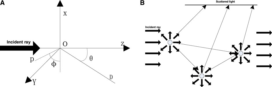
FIGURE 1. Schematic of optical scattering. (A) Single scattering; (B) multiple scattering.
2.2 Polarized light characterization
The Stokes vector method is used for characterizing the polarization of light beams and is applicable to unpolarized, partially polarized, and polarized beams [16–18]. Stokes vectors
where
The polarizability is a covariate characterizing the randomness of the polarization state of the Stokes parameter and is defined as
When
When
3 Test platform construction
The sea fog environment external field polarized light active transmission test was carried out to analyze the energy change, polarization state change, and other characteristics of the test program in linearly polarized light and circularly polarized light at different visibility levels in sea fog environments. The laser light from the transmitter passes through the attenuator, polarizer, and 1/4 wave plate in order to enter the real sea fog environment. The receiving end consists of a filter, a beam splitter prism, an optical power meter, and a polarization meter. The polarization meter is used to calibrate the accuracy of the polarization calculated using the optical power meter method. The polarized light transmission characteristics in the horizontal direction were achieved by placing the transmitting end in a hotel on the one side of the bay and the receiving end in the balcony of the hotel on the other side, as shown in Figure 2. The test site is shown in Figure 3. The tilt angle of the transmitting system and receiving system is adjusted using a three-dimensional rotary table, thus realizing the polarized light transmission characteristic study in the oblique range direction.
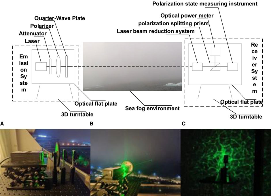
FIGURE 2. Picture of field test equipment. (A) Equipment composed of a laser, an attenuator, a quarter wave plate, and a polarizer at the transmitting end; (B) the schematic diagram of the (C) transmission medium shows that the receiving end includes a polarization state-measuring instrument and an optical power meter.
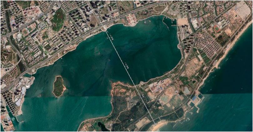
FIGURE 3. Map of field test trial locations. The transmitting end is set up at the Sheraton Hotel in Qingdao, China, and the receiving end is set up at the Wyndham Hotel in Qingdao, China, with a distance of 2.84 km between the two ends.
The tested laser wavelengths are 450 nm, 532 nm, 671 nm, 808 nm, and 1,064 nm. The polarizer modulation method is used to adjust the linearly and circularly polarized light at 0°, 45°, 90°, and 135° by rotating the combination of the polarizer and the wave plate, and the change in the polarization characteristics is recorded through the sea spray at different visibility levels. The accuracy of the test is improved by averaging multiple measurements and measuring environmental parameters in real time. The temperature during the experiment was 27°C, the humidity was 91%, and the wind speed was 3.8 m/s.
4 Results and analysis
4.1 Effect of different polarization states on polarizability at the same visibility level
In this paper, in order to study the variation in polarization with wavelength in different polarization states at the same visibility level, lasers in the wavelength bands of 450, 532, 671, 808, and 1,064 nm are selected to carry out the real-time sea spray test in the Qingdao Sea, China, in the horizontal direction and subsequently plot the variation curves of polarization in different polarization states at the same visibility level.
As shown in Figure 4, the polarization of the emitted polarized light decreases as the visibility of the sea fog decreases, i.e., the concentration of the sea fog increases. The polarization curves of the four linearly polarized lights have the same trend, and the polarization curves of the two circularly polarized lights are identical, which indicates that in the sea fog environment, the starting angle of the linearly polarized light and the change in the rotational direction of the circularly polarized light have almost no effect on the polarization. However, there are some differences in the attenuation degree and trend of linearly polarized light and circularly polarized light. Under the same conditions, the linearly polarized light has more obvious receding polarization, the circularly polarized light shows better polarization preservation characteristics, and the larger the concentration of the sea fog is, the stronger the polarization preservation ability of the circularly polarized light is [16]. Therefore, the ability to penetrate the sea fog can be improved by incident circularly polarized light to enhance the transmission effect of polarized information.
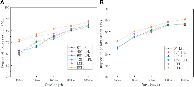
FIGURE 4. Plot of polarization versus different polarization states at the same visibility level: (A) visibility at 8 km; (B) visibility at 10 km. LPL, linearly polarized light; LCPL, left circularly polarized light; RCPL, right circularly polarized light.
4.2 Effect of different wavelengths on polarization at the same visibility level
In this paper, in order to study the variation in polarization with wavelength in different polarization states at the same visibility level, lasers at wavelengths 450, 532, 671, 808, and 1,064 nm are selected to carry out the real-time sea fog test in the Qingdao Sea area of China in the horizontal direction and subsequently plot the variation curves of polarization at different wavelengths at the same visibility level.
As shown in Figure 5, due to the complexity of the real sea spray environment, which contains not only salt spray particles and water spray particles but also many other particles, light is affected by a greater degree of scattering [19, 20]. This results in a maximum of 30% variation in wavelength and 36% variation in polarization states. When visibility is high, the influence of wavelength and polarization states is relatively small. As visibility decreases, the rate of polarization reduction is higher for linearly polarized light than for circularly polarized light. Among them, the 0° linearly polarized light is the most unstable and has the largest degree of receding polarization, while the circularly polarized light maintains a higher polarization all the time. The polarization of linearly polarized light increases rapidly when the wavelength increases from 450 nm to 532 nm. The polarization of circularly polarized light increases rapidly when the wavelength increases from 532 nm to 450 nm. When the wavelength increases from 532 nm to 1,064 nm, the polarization of the linearly polarized light increases gradually, and the circularly polarized light maintains relatively stable polarization-preserving characteristics. Among them, the polarization of the polarized light in the infrared band is 23.65% higher than that of the polarized light in the visible band, which means that in the near-infrared band, the laser light with a longer wavelength can carry more polarization information and maintain a better polarization.
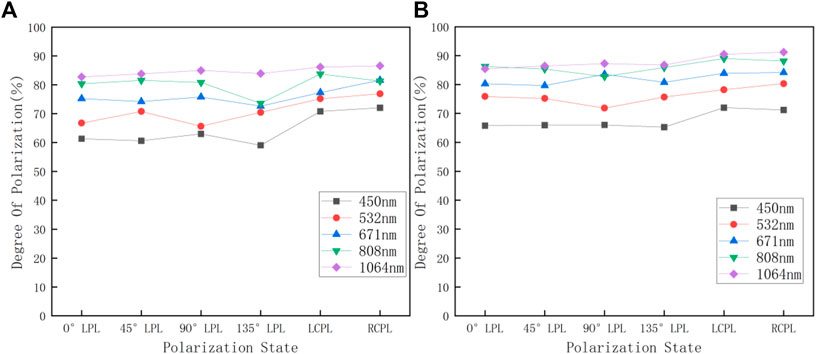
FIGURE 5. Plot of polarization versus different wavelengths at the same visibility level: (A) visibility at 8 km; (B) visibility at 10 km. LPL, linearly polarized light; LCPL, left circularly polarized light; RCPL, right circularly polarized light.
4.3 Effect of different tilt angles on polarization at the same visibility level
In this paper, in order to study the variation in polarization with wavelength at different tilt angles in the same polarization state, lasers with wavelengths of 450, 532, 671, 808, and 1,064 nm are selected to carry out the real-time sea spray test in the Qingdao Sea, China, in the directions of 0°, 45°, and 75°, and then the polarization curves of different tilt angles are plotted at the same visibility level.
As shown in Figure 6, when the tilt angle is 0°, 45°, and 75°, the polarization of the linearly polarized light decreases with the increase in the tilt angle. This is due to the fact that when the tilt angle increases, the transmission medium of the polarized light changes. The size of the sea spray particles increases at the end of the transmission process, and the non-spherical effect of the transmission medium becomes more significant, which results in the enhancement of forward scattering to the polarized light and a decrease in the polarization of the linearly polarized light [21]. The polarization of the linearly polarized light decreases, and the circularly polarized light has better polarization preservation than the linearly polarized light. Furthermore, when the wavelength is 450 nm, the polarization of linearly and circularly polarized light decreases the most, and the polarization of linearly and circularly polarized light decreases with the increase in the wavelength, which further indicates that the laser light with longer wavelength can carry more polarization information and maintain better polarization.
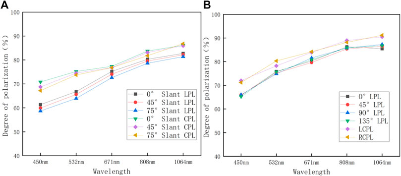
FIGURE 6. Plot of polarization versus different tilt angles at the same visibility level: (A) visibility at 8 km; (B) visibility at 10 km. LPL, linearly polarized light; CPL, circularly polarized light.
5 Conclusion
In this paper, the real-time sea fog test was carried out in the Qingdao Sea area of China in the horizontal/inclined direction by the active test method, and the test results show that when the polarized light is incident at the same visibility level and in the same polarization state in the sea fog environment, the longer wavelength corresponds to the higher degree of polarization, which has a stronger ability to penetrate into the medium. The circularly polarized light has a better ability to maintain polarization than the linearly polarized light. The polarization degree decreases with the increase in the tilt angle, which is due to the fact that the non-spherical effect of the transmission medium is more significant at the end of the transmission process as the size of the sea spray particles increases. The scattering effect of the non-spherical particles of the transmission medium is enhanced, and the circularly polarized light has better polarization-preserving properties than the linearly polarized light. In this paper, because the real outdoor sea spray environment variables are not controllable, there is less need to increase visibility data, which is also the focus of our next work.
Data availability statement
The raw data supporting the conclusion of this article will be made available by the authors, without undue reservation.
Author contributions
KL: data curation, visualization, writing–original draft, and writing–review and editing. QF: data curation, project administration, visualization, writing–original draft, and writing–review and editing. YZ: investigation and writing–review and editing. WY: investigation and writing–review and editing. SZ: methodology and writing–review and editing. JZ: project administration and writing–review and editing. ZL: data curation, methodology. YM: methodology. JD: software and writing–review and editing. HJ: supervision and writing–review and editing
Funding
The author(s) declare that the financial support was received for the research, authorship, and/or publication of this article. This work was supported by the Natural Science Foundation of China (Nos 61890963, 61890960, and 62127813).
Acknowledgments
The authors would like to thank the Natural Science Foundation of China for their help in identifying collaborators for this work.
Conflict of interest
The authors declare that the research was conducted in the absence of any commercial or financial relationships that could be construed as a potential conflict of interest.
Publisher’s note
All claims expressed in this article are solely those of the authors and do not necessarily represent those of their affiliated organizations, or those of the publisher, the editors, and the reviewers. Any product that may be evaluated in this article, or claim that may be made by its manufacturer, is not guaranteed or endorsed by the publisher.
References
1. Al Naboulsi M, Sizun H, de Fornel F. Fog attenuation prediction for optical and infrared waves. Opt Eng (2004) 43(2):319–29. doi:10.1117/1.1637611
2. Ji WM, Jiang FY, Chu CX. Calculation and analysis on scattering characteristics of non-spherical particles of haze. The international archives of photogrammetry. Remote Sensing Spat Inf Sci (2019) 42:83–8. doi:10.5194/isprs-archives-xlii-3-w9-83-2019
3. Zhang Y, Wang Y, Huang A, Hu X. Effect of underwater suspended particles on the transmission characteristics of polarized lasers. JOSA A (2019) 36(1):61–70. doi:10.1364/josaa.36.000061
4. Chu J, Wu Q, Zeng X, Li Y. Forward transmission characteristics in polystyrene solution with different concentrations by use of circularly and linearly polarized light. Appl Opt (2019) 58(25):6750–4. doi:10.1364/ao.58.006750
5. Zhang S, Zhan J, Fu Q, Duan J, Li Y, Jiang H. Effects of environment variation of glycerol smoke particles on the persistence of linear and circular polarization. Opt express (2020) 28(14):20236–48. doi:10.1364/oe.395428
6. Zhang S, Zhan J, Fu Q, Duan J, Li Y, Jiang H. Propagation of linear and circular polarization in a settling smoke environment: Theory and experiment. Appl Opt (2019) 58(17):4687–94. doi:10.1364/ao.58.004687
7. Chamaillard K, Kleefeld C, Jennings S, Ceburnis D, O’Dowd C. Light scattering properties of sea-salt aerosol particles inferred from modeling studies and ground-based measurements. J Quantitative Spectrosc Radiative Transfer (2006) 101(3):498–511. doi:10.1016/j.jqsrt.2006.02.062
8. Laan J, Scrymgeour DA, Kemme SA, Dereniak EL. Detection range enhancement using circularly polarized light in scattering environments for infrared wavelengths. Appl Opt (2015) 54(9):2266–74. doi:10.1364/ao.54.002266
9. Gilerson A, Carrizo C, Foster R, Harmel T. Total and polarized radiance from the ocean surface from hyperspectral polarimetric imaging. In: Proceedings of the Ocean Sensing and Monitoring XI; April 2016; Baltimore, Maryland, USA (2019).
10. Duan J, Qu Y, Fu Q, Yu T, Yang Y, Zhang S, et al. Polarized light transmission characteristics in a smoky ellipsoidal particle medium. Appl Opt (2023) 62(10):2510–21. doi:10.1364/ao.480857
11. Ryu HS, Hong S. Sea fog detection based on Normalized Difference Snow Index using advanced Himawari imager observations. Remote Sensing (2020) 12(9):1521. doi:10.3390/rs12091521
12. Guo X, Wan J, Liu S, Xu M, Sheng H, Yasir M. A scSE-LinkNet deep learning model for daytime Sea Fog detection. Remote Sensing (2021) 13(24):5163. doi:10.3390/rs13245163
13. Wang P, Li D, Wang X, Guo K, Sun Y, Gao J, et al. Analyzing polarization transmission characteristics in foggy environments based on the indices of polarimetric purity. IEEE Access (2020) 8:227703–9. doi:10.1109/access.2020.3045993
14. Jeon HK, Kim S, Edwin J, Yang CS. Sea fog identification from GOCI images using CNN transfer learning models. Electronics (2020) 9(2):311. doi:10.3390/electronics9020311
15. Zhang C, Zhang J, Wu X, Huang M. Numerical analysis of light reflection and transmission in poly-disperse sea fog. Opt Express (2020) 28(17):25410–30. doi:10.1364/oe.400002
16. Guan L, Shiqi L, Zhai L, Liu S, Liu H, Lin W, et al. Study on skylight polarization patterns over the ocean for polarized light navigation application. Appl Opt (2018) 57(21):6243–51. doi:10.1364/ao.57.006243
17. van der Laan JD, Wright JB, Kemme SA, Scrymgeour DA. Superior signal persistence of circularly polarized light in polydisperse, real-world fog environments. Appl Opt (2018) 57(19):5464–73. doi:10.1364/ao.57.005464
18. Fu Q, Luo K, Song Y, Zhang M, Zhang S, Zhan J, et al. Study of sea fog environment polarization transmission characteristics. Appl Sci (2022) 12(17):8892. doi:10.3390/app12178892
19. Yang B, Yan CX. Multi-spectral polarized properties of ocean aerosol. GuangpuxueyuGuangpu fen xi (2016) 36(9):2736–41. doi:10.3964/j.issn.1000-0593(2016)09-2736-06
20. Huang J, Wang B, Wang X, Huang F, Lü W, Jing T. The spring yellow Sea fog: Synoptic and air–sea characteristics associated with different airflow paths. Acta OceanologicaSinica (2018) 37(1):20–9. doi:10.1007/s13131-018-1155-y
Keywords: sea fog environment, polarized light, transmission properties, different wavelengths, visibility
Citation: Luo K, Fu Q, Zhang Y, Yang W, Zhang S, Zhan J, Li Z, Ma Y, Duan J and Jiang H (2023) Characterization of multi-wavelength polarized light transmission in the real sea spray environment. Front. Phys. 11:1264360. doi: 10.3389/fphy.2023.1264360
Received: 20 July 2023; Accepted: 04 September 2023;
Published: 19 September 2023.
Edited by:
Jingsong Li, Anhui University, ChinaReviewed by:
Qingbin Jiao, Chinese Academy of Sciences (CAS), ChinaFupeng Wang, Ocean University of China, China
Copyright © 2023 Luo, Fu, Zhang, Yang, Zhang, Zhan, Li, Ma, Duan and Jiang. This is an open-access article distributed under the terms of the Creative Commons Attribution License (CC BY). The use, distribution or reproduction in other forums is permitted, provided the original author(s) and the copyright owner(s) are credited and that the original publication in this journal is cited, in accordance with accepted academic practice. No use, distribution or reproduction is permitted which does not comply with these terms.
*Correspondence: Qiang Fu, Y3VzdF9mdXFpYW5nQDE2My5jb20=