Abstract
To overcome the drawbacks of the existing sinusoidal map and tent map, this paper proposes the design of a sinusoidal–tent (ST) map. The test results indicate that the new chaotic system exhibits more significant advantages in chaos control. Compared with the sinusoidal map and tent map, the proposed sinusoidal–tent map performs better in terms of bifurcation diagram and Lyapunov exponents. The trajectories of the sinusoidal–tent map can occupy all the phase planes over (0,4), while those of the two classic maps only occupy a small phase space, and the Lyapunov exponents of the ST map are all positive within the range of control parameters, higher than those of seed maps. Simultaneously, a novel quantum scrambling operation is devised based on the sinusoidal–tent map to avoid the periodicity of the quantum Arnold scrambling method. Initially, two chaotic sequences are generated to scramble the pixel positions of the watermark image, further enhancing the security of the watermarking algorithm. Subsequently, the host image is processed by the quantum discrete cosine transform, and finally, the scrambled watermark image is inserted into the medium-frequency band of the transformed host image, ensuring the invisibility of the watermarking. According to the simulation results, the quantum watermarking algorithm has excellent invisibility and robustness.
1 Introduction
Information security is indeed a crucial field in the era of big data. Image information security is one of its significant branches that have witnessed rapid development over the past few decades [1–5]. Particularly, benefiting from the entanglement characteristics and the powerful parallel computing abilities, quantum computing has the potential to overcome the limitations of classical computation. Quantum computing is a computational model that employs quantum bits, utilizing the principles of quantum mechanics to process information. Traditional computers use bits (0 or 1) as the smallest units for storage and processing, while quantum computers use quantum bits, often referred to as “qubits.” Qubits can not only represent the states of 0 and 1 but also exist in superstitions of these states, a key aspect of quantum parallelism [6].
During signal transmission, the computing complexity of quantum operations has been effectively reduced, thereby significantly increasing information security through quantum computing. Beach et al. [7] highlighted and analyzed the doubts surrounding quantum image processing, demonstrating the true quantum superiority in quantum image classification and recognition. To improve the fault tolerance of quantum circuits, Li et al. [8] implemented cyclic and complete translations on quantum images through quantum arithmetic operations and realized the scalar matrix multiplication by designing fault-tolerant circuits for these operations with the TR and Peres gates. The mid-point filter, which is an order statistic filter, cannot be directly used in the frequency domain. As a solution, Ali et al. [9] introduced a new quantum mid-point filter designed specifically for spatial domain applications. This proposed approach maintains the same level of noise suppression as the classical version but significantly reduces the complexity.
For different purposes, various representation models of quantum images have been investigated [10–14]. The first flexible representation of the quantum image (FRQI) was invented to encode the position information and color information of an image into a single quantum state [10]. A novel enhanced quantum representation (NEQR) was explored to quadratically speed up the preparation of quantum images and enhance the compression ratio of quantum images [11]. The radiation energy value of a pixel in infrared images could be stored using the probability of projection measurement [12]. A quantum scaling-up algorithm for images was proposed using nearest-neighbor interpolation [14]. In addition, researchers have also developed several models for quantum color image representation, such as NCQI [15], MQIR [16], and DQRCI [17].
Digital watermarking is a technique that embeds specific information within digital media, with the aim of verifying or identifying the authenticity, ownership, or source of digital content. This technology is commonly used in digital media files such as images, audio, and videos [18]. To address the security issue in copyright protection, various watermarking strategies have been explored [19, 20]. Gong et al. [19] proposed a watermarking scheme for double-color images, which involved the use of quaternion fractional-order orthogonal Fourier–Mellin moments and geometric correction. Different from classical watermarking algorithms, quantum watermarking algorithms (QWAs) combine principles of quantum computation theory and watermarking strategies [20, 21]. A quantum watermarking scheme was enhanced by utilizing the novel enhanced quantum representation (NEQR) along with a color scrambling technique and small-scale quantum circuits [22]. In order to improve the visual quality and embedding capacity, Zeng et al. [23] proposed a quantum watermarking algorithm by combining the maximal pixel difference with the tent map. A self-recovery QWA was devised with block truncation coding to increase the key space and improve security [24]. In 2021, Li et al. [25] proposed a quantum watermarking scheme for the quantum hue, saturation, and lightness (QHSL) image in the spatial domain. The scheme aimed to protect the integrity and ownership of QHSL images against various attacks. A QWA was presented with the quantum Fourier transformation [26]. Similarly, a quantum image watermarking algorithm was investigated by the quantum Haar wavelet transform [27]. The discrete cosine transform (DCT) is a Fourier-related transform similar to the discrete Fourier transform but using only real numbers [28]. The utilization of DCT shifts an image from the time domain to the frequency domain, where most of the signal information is focused on the low-frequency bands situated in the upper-left corner. DCT is frequently employed for lossy compression, as seen in the JPEG compression of digital images and the MP3 compression of digital audio, owing to its robust energy compaction features. Simultaneously, DCT coefficients in the high-frequency bands, located in the lower-right corner, are nearly zero. Building upon the aforementioned characteristics of the DCT, Mohsen et al. [29] proposed a quantum watermarking algorithm for audio using the quantum discrete cosine transform (QDCT). This algorithm utilizes QDCT, a quantum counterpart of the classical DCT, to achieve enhanced information compression performance inherited from the DCT. Overall, the use of QDCT in audio watermarking offers advantages in terms of imperceptibility and robustness. However, it is important to conduct further research to evaluate the effectiveness and security of QDCT-based QWAs in practical applications and against more sophisticated attacks.
Quantum image scrambling techniques were invented for quantum watermarking due to the superiority of quantum computing models. The quantum Arnold transform is one of the common and available image scrambling methods [30]. However, the risk from the periodicity of the Arnold transform is unavoidable, as attackers can restore the scrambled image with sufficient computing resources. In order to mitigate this risk, a new quantum image scrambling operation using the sinusoidal–tent map is proposed here. This map is a 1D chaotic map which is chosen due to its simple structure and easy implementation. The sinusoidal–tent map exhibits more significant advantages in spatiotemporal performance and chaotic characteristics compared to the sinusoidal map and tent map. Additionally, a quantum color watermarking algorithm is studied by integrating the QDCT with the sinusoidal–tent map, and a quantum network for the proposed quantum image watermark embedding is also devised.
2 Fundamental knowledge
2.1 NCQI model
The NCQI model storing a quantum color image of size was mathematically defined as Eq. 1 [15]where denotes the color value of the associated pixel encoded by a binary sequence and is expressed as the following Eq. 2.
The grayscale value of each channel , or ranges from 0 to . The NCQI model can store a color image in a normalized quantum superposition state. To represent a pixel, the color information and the vertical and horizontal positions and are involved. As for any by color image with channel , or ranging from 0 to , there are qubits involved to store it into an NCQI state.
2.2 Novel enhanced quantum representation
As a commonly used quantum representation of images, NEQR stores the gray information of each image pixel via the basis state of a qubit sequence, and it performs well because of its accuracy and flexibility. Assume that the gray value of an image pixel ranges from 0 to and is a binary sequence encoding the pixel value , then Eq. 3 is obtained.
A quantum image of size could be written as Eq. 4.
A quantum binary image of size can be written as Eq. 5.where and represent black and white, respectively.
The calculation of the absolute value (CAV) of two n-qubit sequences can be implemented by integrating the above RPS and CO modules [31].
To determine whether two input quantum sequences and are equal, a quantum equal (QE) module was designed by Zhou et al. [32].
2.3 Quantum discrete cosine transform
The quantum discrete cosine transform on a by image is defined mathematically as Eq. 6 and Eq. 7.
Module is the quantum Fourier transform on qubits, and in Eq. 8, and are operation matrices extracted from matrices and , respectively, where . Figure 1 illustrates the whole QDCT quantum circuit.
FIGURE 1
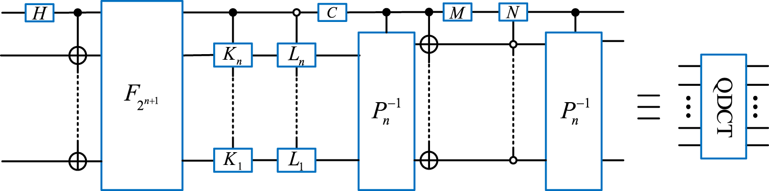
Quantum circuit of QDCT.
3 Quantum color image watermarking scheme
3.1 Improved quantum module
3.1.1 Improved reversible half-subtractor
Figure 2 illustrates the quantum circuits and quantum modules of the proposed improved reversible half-subtractor (IRHS) according to [31]. The IRHS module performs the half-subtraction operation. represents the difference between single qubits and , and denotes the corresponding borrow bit. The quantum circuit of IRHS shown in Figure 2 saves one CNOT gate and one qubit compared with the RHS [31]. The complexity of () is 1, and that of the CNOT gate is also 1. Therefore, the complexities of the RHS and IRHS modules are 8 and 7, respectively.
FIGURE 2
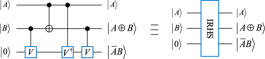
Circuit of IRHS and its quantum module.
3.1.2 Improved reversible full-subtractor
An improved reversible full-subtractor (IRFS) based on [31] is redesigned, as shown in Figure 3. Different from the quantum circuit of RFS, the IRFS module economizes a qubit and one CNOT gate. The IRFS module performs a full-subtraction operation, where the outputs and denote and the corresponding borrow bit, respectively. The complexities of quantum circuits of the RFS and IRFS modules are 11 and 10, respectively.
FIGURE 3
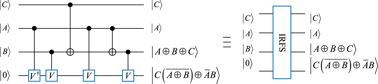
Circuit of IRFS and its quantum module.
3.1.3 Improved reversible parallel subtractor
A reversible parallel subtractor (RPS) usually involves RHS and RFS [31], and thus the improved reversible parallel subtractor (IRPS) for sequences can be implemented by combining IRHS and IRFS. As shown in Figure 4, the sequence denotes the difference between sequence and sequence . Obviously, the complexities of the single IRPS and RPS modules are and , respectively.
FIGURE 4
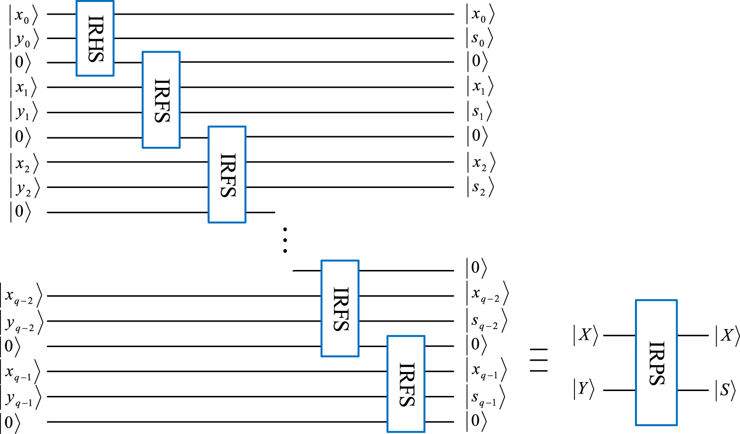
Quantum circuit of IRPS and its quantum module.
3.1.4 Improved calculation of the absolute value
The quantum module CAV consists of RPS and CO [31]. Figure 5 shows the proposed improved calculation of the absolute value (ICAV), which consists of CO and IRPS. A CO module is composed of CNOT gates, one Toffoli gate, and some operation gates.
FIGURE 5
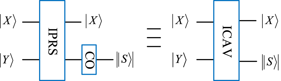
Quantum module of ICAV.
3.2 Sinusoidal–tent map
3.2.1 Sinusoidal map
The sinusoidal map is a common one-dimensional chaotic map [33] and is defined as Eq. 9.where and is the control parameter within the range of . The bifurcation and Lyapunov exponent plots of the sinusoidal map are shown in Figure 6A; Figure 7A, respectively. The Lyapunov exponents and bifurcation diagram serve as crucial metrics in discerning the chaotic characteristics of systems exhibiting chaos. In the case of a chaotic map, the onset of chaotic behaves when its Lyapunov exponents surpass zero. As illustrated in Figure 6A, the Lyapunov exponents of the sinusoidal map exceed 0 only under specific control parameters . Furthermore, as depicted in Figure 7A, the values of the chaotic sequence generated by the sinusoidal map are irregularly distributed within the chaotic range . These observations suggest that the sinusoidal map demonstrates suboptimal chaos behavior, imposing significant limitations on its practical applicability.
FIGURE 6
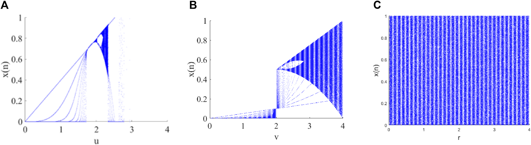
Trajectories of different chaotic maps: (A) sinusoidal map with parameter , (B) tent map with , and (C) sinusoidal–tent map with parameter .
FIGURE 7
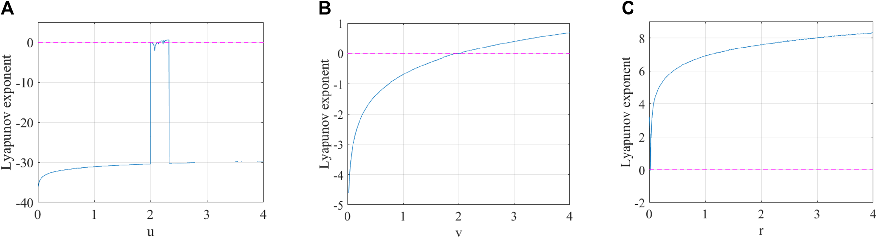
Lyapunov exponents of different chaotic maps: (A) sinusoidal map with parameter , (B) tent map with parameter , and (C) sinusoidal–tent map with parameter .
3.2.2 Tent map
The tent map is a one-dimensional piece-wise linear map [34] and is defined as Eq. 10.where and is the parameter within the range of (0, 4]. The bifurcation and Lyapunov exponent plots of the tent map are shown in Figure 6B; Figure 7B, respectively. When , the tent map is chaotic. Therefore, this mapping also shares the same issues as the sinusoidal mapping technique.
3.2.3 Sinusoidal–tent map
By combining the sinusoidal map with the tent map, a sinusoidal–tent map as the new chaotic map is designed as Eq. 11.where the parameter and is the output chaotic sequence. Compared with the sinusoidal and tent maps, the designed sinusoidal–tent map performs better in terms of bifurcation diagram and Lyapunov exponents. As shown in Figure 6, the bifurcation of ST is distributed across the entire data range of the plane. This distribution area is significantly larger than the outputs of the sinusoidal map and tent map. By observing Figure 7, it can be noted that the Lyapunov exponents of the ST map are all positive within the range of control parameters, indicating favorable chaotic characteristics.
3.3 Quantum scrambling with the sinusoidal–tent map
The Arnold scrambling method is insecure with sufficient computing resources owing to its periodicity. Therefore, we put forward a new irregular scrambling method. The scrambling on a quantum image is as follows:
(1) a and b are chosen as initial parameter values of the sinusoidal–tent map. Then, two chaotic sequences and are generated using the sinusoidal–tent map, where j represents the jth iteration. Then, the two chaotic sequences are converted into integer sequences and , respectively, which are represented as Eq. 12 and Eq. 13.
(2) The original image is then scrambled via the element values of and , where and express the quantum states of sequences and , respectively. The quantum image position scrambling operation is denoted as , and the scrambled image is represented as Eq. 14.where and represents the absolute value operation. The quantum module of this scrambling operation is shown in Figure 8.
FIGURE 8

Circuit of the quantum scrambling operation.
3.4 Watermark embedding procedure
During the watermark embedding process, the color image is watermarked with a binary watermark . Figure 9 shows the embedding procedure of the quantum color image watermarking algorithm, and the detailed embedding process is given below.
FIGURE 9
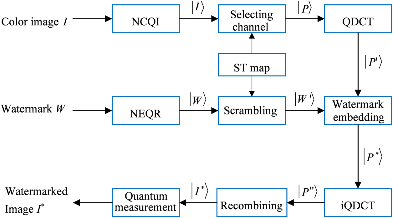
Embedding procedure of the quantum watermarking algorithm.
Step 1The classical image of size is transformed into a quantum image by the NCQI.
Step 2With the initial parameter value a of the sinusoidal–tent map, one chaotic sequence is produced using the sinusoidal–tent chaotic map. The chaotic sequence is changed to an integer sequence :According to Eq. 16, if equals to 0, 1, or 2, then R, G, or B channel of the quantum image is chosen to embed the watermarking image, i.e., .
Step 3The original watermark of size is transformed into a quantum image by the NEQR. Then, a scrambled quantum watermarked image is yielded by executing the quantum scrambling operation S on . The quantum scrambling circuit is shown in Figure 8.
Step 4Image is translated into the frequency domain by the QDCT operation. The energy of the QDCT coefficients is mainly congregated in the upper-left corner of the sub-block, which is the low-frequency part of an image, and most of the remaining coefficients are very close to zero. Therefore, the medium-frequency part is a better area to embed the watermark compared with the low-frequency part. is an image transformed using the QDCT operation.
Step 5The medium-frequency QDCT coefficients of every sub-block are selected randomly and embedded with a quantum image multiplied by a coefficient to obtain by Eq. 17:
Step 6After executing the inverse QDCT on to obtain , the final color image inserted with a secret message can be yielded from the reconstructed and other channels.A quantum watermark embedding network is shown in Figure 10, where and . E(k) denotes the scrambled quantum watermarked image multiplied by the watermark embedding coefficient .
FIGURE 10
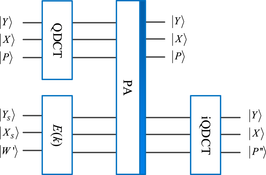
Quantum watermark embedding network.
3.5 Watermark extraction
The watermark image is extracted from a watermarked quantum color image with the help of the color host image and the keys to choose the embedded channel and scramble the watermark image. Figure 11 shows the extraction of the designed quantum color image watermarking algorithm, and the extraction process is detailed below.
FIGURE 11
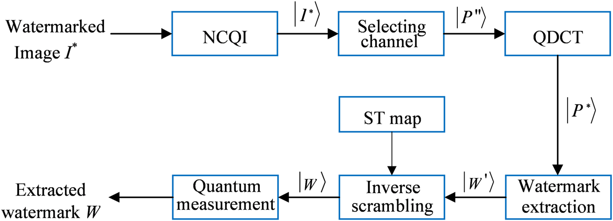
Extraction procedure of the quantum watermarking algorithm.
Step 1First, in order to extract the watermark image from the host image, the classical watermarked image should be transformed into the corresponding quantum state by the NCQI.
Step 2The chaotic sequence is generated by the sinusoidal–tent map with the same initial parameter a. According to Eq. 15 and Eq. 16, the random sequence is converted into the random integer sequence . In the following, if equals to 0, 1, or 2, the corresponding R, G, or B channel with a watermark image can be easily chosen from the final color image .
Step 3This step is only to perform QDCT on the watermarked image in order to recover the quantum image .
Step 4 can be obtained by performing the QDCT operation on image . According to the corresponding medium-frequency embedding position, the scrambled watermark image could be obtained as Eq. 18.
Step 5The sequences and are then generated using the sinusoidal–tent map controlled by the initial parameters a and b, respectively. By recalling and , the extracted watermark image is acquired by executing the inverse scrambling operation shown in Eq. 19:
Step 6After quantum measurement, the quantum watermark image is eventually translated into a classical image.
4 Numerical simulation and discussion
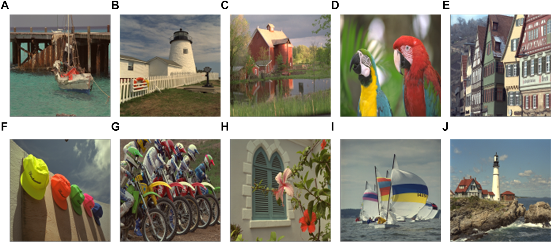
The numerical simulations are carried out under the MATLAB R2017b platform on a classical PC. Ten host color images of size taken for the test are shown in Figure 12. Two binary watermark images of sizes and are shown in Figure 13. The initial values a and b and the control parameter r of the sinusoidal–tent map are set to 0.325, 0.333, and 0.1, respectively, and the embedding coefficient k of the proposed color image QWA is set at 0.01.
FIGURE 12
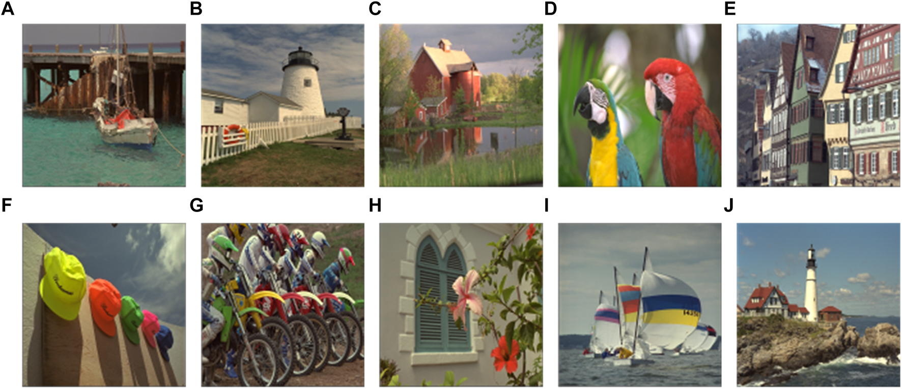
Ten selected test images of size : (A) “Boat,” (B) “White house,” (C) “Villa,” (D) “Parrot,” (E) “Building,” (F) “Hats,” (G) “Motorbike,” (H) “Flower,” (I) “Yacht,” and (J) “Beacon.” Adapted with permission from [37], licensed by Eastman Kodak Company.
FIGURE 13
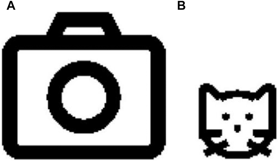
Watermark images: (A) “Camera” of size . (B) “Cat” of size . Adapted with permission from [37], licensed by Eastman Kodak Company.
The scrambling operation S is executed on the watermark image “Camera” and “Cat,” and Figures 14A, B show the corresponding scrambled watermark images. As shown in Figure 14, the proposed scrambling operation has an acceptable scrambling performance.
FIGURE 14
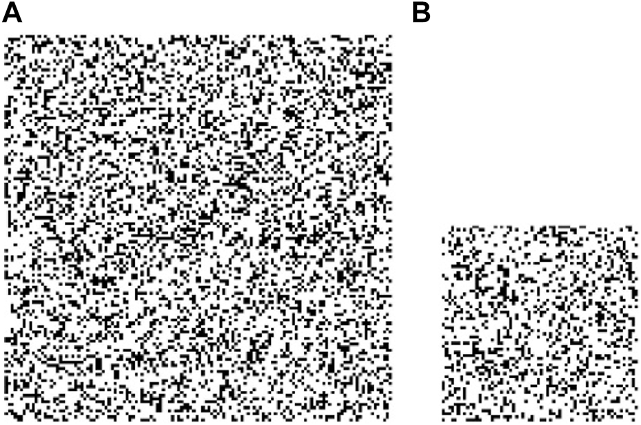
Scrambled watermark images: (A) “Camera.” (B) “Cat.”
4.1 Watermark evaluation exponents
The peak signal-to-noise ratio (PSNR) is expressed as Eq. 20.where is the maximal image grayscale value, is the mean-squared error between the host image and its associated watermarked image , and is the number of pixels in an image.
The structural similarity exponent matrix (SSIM) can assess the distortion of an image or the similarity of two images according to Eq. 21:where and are constants, and are the variance value and the mean value, respectively, and is the covariance value of x and y.
Normalized cross-correlation (NCC) is another important exponent to assess the similarity of two images and is usually employed to measure the robustness of watermarking algorithms against different attacks, which is expressed as Eq. 22.
Here, is the image size. and represent the pixel values of images and at the position , respectively. The NCC value is in the range of . The closer the NCC value is to 1, the more similar the two images are.
4.2 Imperceptibility analysis
Figures 15A–E show the watermarked color images with the watermark image “Camera,” while Figures 15F–I show the watermarked images with the watermark image “Cat.” By observing and comparing Figure 12; Figure 15, it can be observed that there is no significant difference between the watermarked image and the original host image.
FIGURE 15
Watermarked image with “Camera”: (A) “Boat,” (B) “White house,” (C) “Villa,” (D) “Parrot,” and (E) “Building.” Watermarked image with “Cat”: (F) “Hats,” (G) “Motorbike,” (H) “Flower,” (I) “Yacht,” and (J) “Beacon.” Adapted with permission from [37], licensed by Eastman Kodak Company.
The values listed in Table 1 represent the PSNR and SSIM for the watermark image with two different sizes. The PSNR is mainly used for the evaluation and comparison of image and video compression algorithms and can help measure the impact of different compression algorithms on the quality of images or videos. The higher the value of the PSNR, the smaller the difference between two images, indicating higher quality. Generally, if the PSNR value is greater than 30 dB, it is hard to differentiate between the original host image and the watermarked image. If the PSNR value is greater than 40 dB, then the invisibility of the image watermark algorithm can be ensured. As for the watermark images “Camera” and “Cat,” the average PSNR values of the host image and the watermarked image with the proposed QWA are 46.76 dB and 52.60 dB, respectively. It indicates that the quality of the watermarked image and the corresponding original host image are very close. In addition, the SSIM values of the host image and the watermarked one approach 1. The SSIM value ranges from 0 to 1, where 1 indicates that the two images are identical and 0 indicates that the two images are completely different. A higher SSIM value indicates that the two images are more similar. Therefore, the proposed color image watermark algorithm has good invisibility.
TABLE 1
| Watermark image | Host image | PSNR | SSIM |
|---|---|---|---|
Camera 128×128  | Boat | 48.24 | 0.9974 |
| House | 46.11 | 0.9965 | |
| Villa | 46.78 | 0.9967 | |
| Parrot | 46.06 | 0.9980 | |
| Building | 45.94 | 0.9987 | |
| Hats | 46.73 | 0.9976 | |
| Motorbike | 48.39 | 0.9992 | |
| Flower | 46.38 | 0.9976 | |
| Yacht | 45.68 | 0.9919 | |
| Beacon | 47.26 | 0.9978 | |
Cat 64×64  | Boat | 54.18 | 0.9995 |
| House | 51.80 | 0.9992 | |
| Villa | 52.32 | 0.9990 | |
| Parrot | 51.87 | 0.9995 | |
| Building | 51.56 | 0.9996 | |
| Hats | 52.56 | 0.9994 | |
| Motorbike | 53.90 | 0.9998 | |
| Flower | 52.58 | 0.9995 | |
| Yacht | 51.83 | 0.9985 | |
| Beacon | 53.44 | 0.9996 |
PSNR and SSIM values with the proposed QWA.
In image processing, histograms are valuable tools for analyzing various image features, such as contrast, brightness, and color distribution. By comparing histograms of different images, we can determine their similarities or differences. For instance, if the histograms of two images are closely matched, it suggests that they may have comparable color distributions, indicating their similarity. In Figure 16, the histogram of the watermarked image is similar to the histogram of the original carrier image. This implies that the pixel intensity distributions of the two images may be similar. This can be considered evidence that the watermark image has been successfully embedded into the original carrier image without significantly altering the pixel distribution characteristics of the images. Figures 16A–C show the histograms of three selected host images: “Boat,” “Villa,” and “Hats,” respectively. Figures 16D–F show the histograms of the associated watermarked images. In Figure 16, the histogram of the watermarked image closely resembles that of the original carrier images. This similarity implies that the pixel intensity distributions of the two images may be comparable. Thus, this similarity serves as evidence that the watermark image has been successfully embedded into the original carrier image without significantly altering its pixel distribution characteristics.
FIGURE 16
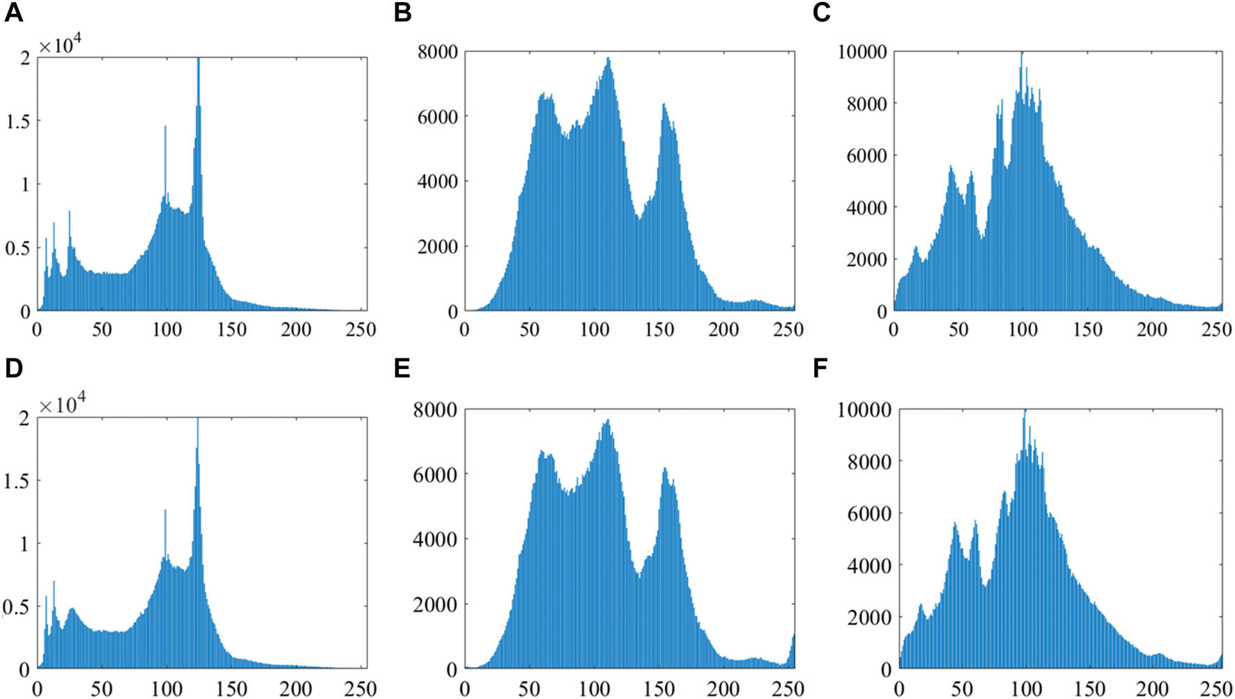
(A–C) Histograms of host images “Boat,” “Villa,” and “Hats,” respectively; (D–F) histograms of the corresponding watermarked host images.
4.3 Robustness analysis
The image “Cat” of size and image “Boat” of size are treated as the watermark image and host image, respectively. As shown in Figure 17, there are no significant difference between the watermarked image and the original host image and no significant distinction between the extracted watermark image and the original watermark image. Noise attack, JPEG compression attack, and filtering attack are used to test the robustness of this algorithm.
FIGURE 17
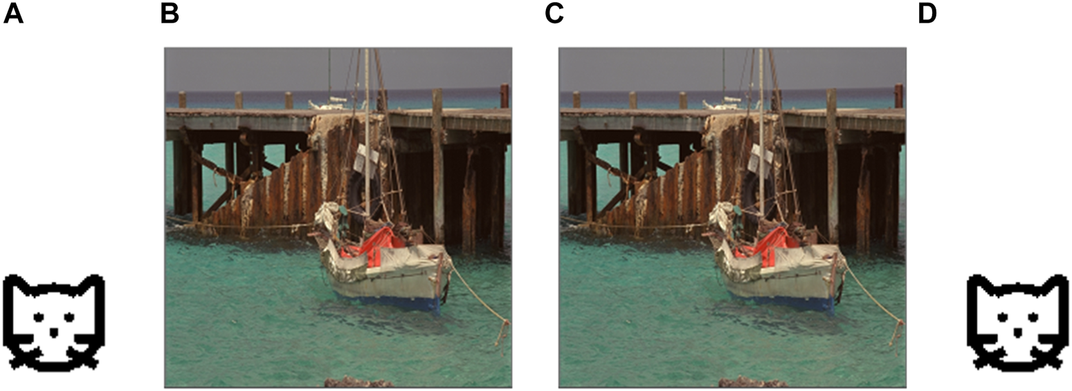
(A) Watermark image “Cat,” (B) host image “Boat,” (C) watermarked image, and (D) extracted watermark image. Adapted with permission from [37], licensed by Eastman Kodak Company.
4.3.1 Noise attack
Noise attack is a common method used to test the robustness of algorithms against the addition of noise in images. By conducting noise attack tests, the robustness of image processing algorithms against different intensities and types of noise can be evaluated. Salt-and-pepper noise with densities of 0.01, 0.03, and 0.05 was added to the watermarked image “Boat.” The watermarked images, along with the corresponding extracted watermark images containing the respective noises, are shown in Figure 18. The NCC values of the extracted watermark images with the added noises are shown in Table 2. From Table 2, it can be observed that the proposed QWA performs well in terms of withstanding noise attacks.
FIGURE 18
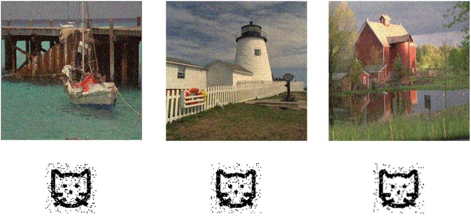
Test result of salt-and-pepper noise attack (intensity 0.05). Adapted with permission from [37], licensed by Eastman Kodak Company.
TABLE 2
| Salt-and-pepper noise intensity | NCC value | ||
|---|---|---|---|
| Boat | House | Villa | |
| 0.01 | 0.9787 | 0.9720 | 0.9854 |
| 0.03 | 0.9640 | 0.9612 | 0.9679 |
| 0.05 | 0.9498 | 0.9432 | 0.9613 |
Test results of salt-and-pepper noise attack.
4.3.2 JPEG compression attack
A JPEG compression attack refers to applying different intensities of JPEG compression to an image with an embedded watermark and evaluating the watermark extraction effectiveness in the compressed image. The experimental results of JPEG compression attacks are shown in Table 3. Quality factor parameters used for JPEG compression in the experiment are set to 90, 70, and 50, respectively. Figure 19 shows the watermarked images subjected to different intensities of JPEG compression attacks, along with the corresponding extracted watermark images. Notably, even when the quality factor parameter was set to 50, the extracted watermark images remained complete and clear, with all corresponding NCC values exceeding 0.98. As a result, the presented quantum color image watermarking algorithm demonstrates resistance against JPEG compression attacks.
TABLE 3
| JPEG compression | NCC value | ||
|---|---|---|---|
| Boat | House | Villa | |
| QF = 90 | 0.9987 | 0.9952 | 0.9959 |
| QF = 70 | 0.9950 | 0.9912 | 0.9915 |
| QF = 50 | 0.9921 | 0.9884 | 0.9873 |
Test results of JPEG compression attack.
FIGURE 19
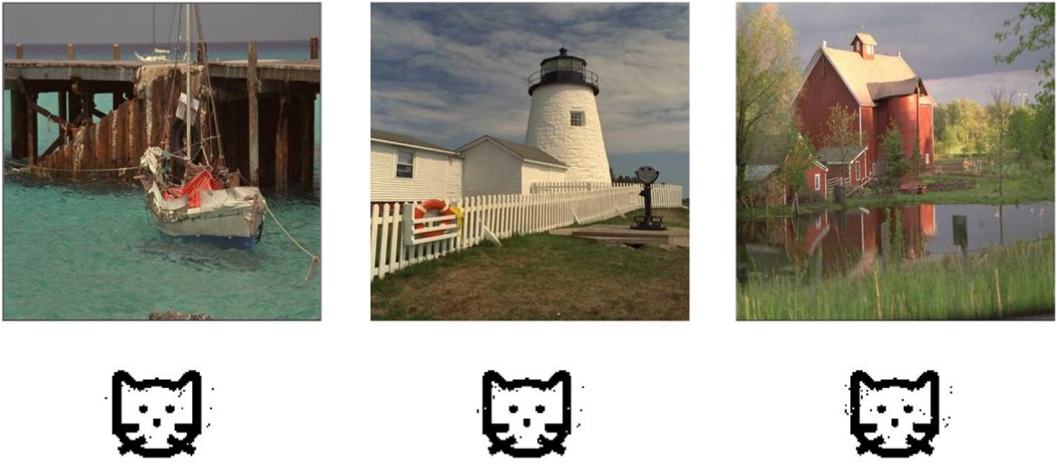
Result of JPEG compression attack (QF = 50). Adapted with permission from [37], licensed by Eastman Kodak Company.
4.3.3 Filtering attack
A filtering attack refers to a type of cyber-attack in which an attacker tries to block or filter out certain information or content from reaching its intended recipient. The median filtering with a filtering window is exploited to interfere with the watermarked image. Table 4 shows the watermark images extracted from the host images under filtering attack and the corresponding NCC values. The NCC values corresponding to the extracted watermark image are all above 0.99. As a result, the proposed color image QWA can resist filtering attacks.
TABLE 4
| Watermark image | Boat | House | Villa |
|---|---|---|---|
| Extracted watermark |  |  |  |
| NCC value | 0.9945 | 0.9918 | 0.9901 |
Test results of filtering attack.
4.4 Comparative analysis
The imperceptibility of the proposed QWA compared with other typical algorithms [21, 35, 36] is shown in Tables 5, 6. Notably, the QWA exhibits superior performance with PSNR and SSIM values when compared to the algorithms referenced in [21, 35, 36]. This enhancement in imperceptibility within the proposed algorithm is attributed to the strategic embedding of the watermark into the medium-frequency component of the transformed host image. By focusing on this frequency range, the QWA achieves a balance between robust watermark insertion and minimizing perceptual impact, thereby ensuring an improved level of invisibility compared to the referenced algorithms. The utilization of the medium-frequency component allows the proposed QWA to maintain the visual quality of the watermarked image while successfully concealing the embedded information.
TABLE 5
| Host image | [21] | [35] | [36] | Proposed scheme |
|---|---|---|---|---|
| Strength k | 0.01 | 1 | 0.01 | 0.01 |
| Watermark size | ||||
| Average value | 51.466 | 37.2960 | 30.4624 | 52.3460 |
PSNR values calculated using the proposed scheme and previous works.
TABLE 6
| Host image | [21] | [35] | [36] | Proposed scheme |
|---|---|---|---|---|
| Strength k | 0.01 | 1 | 0.01 | 0.01 |
| Watermark size | ||||
| Average value | 0.9800 | 0.9432 | 0.9371 | 0.9994 |
SSIM values calculated using the proposed scheme and previous works.
4.5 Quantum circuit complexity analysis
The complexity of our proposed color image QWA is mainly related to the quantum scrambling operation and the QDCT. The presented quantum scrambling operation can be realized with two ICAV modules, one QE module, two PA modules, and two PS-MOD modules. For an image of size , the complexity of a ICAV module is . The QE module involves CNOT gates and a gate, so its complexity is . The complexity of PA and PS-MOD is . Apparently, the complexity of the scrambling operation is . For an image of size , the computing complexity of the QDCT is . To sum up, the complexity of the proposed color image QWA is .
5 Conclusion and future challenges and directions
5.1 Conclusion
A one-dimensional chaotic map, i.e., a sinusoidal–tent map, is devised by combining the sinusoidal map with the tent map. Depending on the random sequence generated using the sinusoidal–tent map, a new position scrambling operation on a quantum image together with the associated quantum circuit is devised. The original quantum circuits of some existing quantum modules are improved to reduce their complexities. The security of QWA is enhanced by using the sinusoidal–tent map to scramble the watermark image. After the quantum discrete cosine transform, most of the signal energy is concentrated on the low-frequency part; thus, choosing the medium-frequency component to embed watermark can enhance the invisibility and robustness of the algorithm. The experimental results illustrate that the QWA has good invisibility and high robustness against noise attack, JPEG compression attack, and filtering attack.
5.2 Potential future challenges and directions
Currently, the quantum watermark technology is generally implemented by simulating quantum theory on classical computers, and there are no well-developed quantum devices available for testing. Therefore, future challenges lie in continuously adjusting the direction of quantum watermark algorithms to cater to the development of quantum computers. This will require proposing algorithms that are better suited for quantum computer applications. Therefore, the future research directions for quantum watermarking will focus on algorithm development, physical implementation, robustness analysis, and application expansion. By exploring these areas, we can create more opportunities and face new challenges in protecting digital content, enhancing information security, and advancing quantum technology.
Statements
Data availability statement
The datasets presented in this article are not readily available. The data and implementation code for MATLAB are available upon request. Requests to access the datasets should be directed to ppzeng@ncu.edu.cn.
Author contributions
P-PZ: conceptualization, funding acquisition, investigation, methodology, validation, and writing–original draft. XZ: formal analysis, software, and writing–original draft. D-FZ: data curation, visualization, and writing–review and editing. S-HC: data curation, validation, and writing–review and editing. L-HG: project administration, supervision, validation, and writing–review and editing.
Funding
The author(s) declare that financial support was received for the research, authorship, and/or publication of this article. This work was supported by the National Natural Science Foundation of China (Grant Nos 62202252 and 61861029), the Science and Technology Planning Project of Shanghai (Grant No. 23010501800), the Science and Technology Research Project of Jiangxi Education Department (GJJ2203915), and the Higher Education Reformation Project of Jiangxi Province (JXJG-22-30-5).
Conflict of interest
The authors declare that the research was conducted in the absence of any commercial or financial relationships that could be construed as a potential conflict of interest.
Publisher’s note
All claims expressed in this article are solely those of the authors and do not necessarily represent those of their affiliated organizations, or those of the publisher, the editors, and the reviewers. Any product that may be evaluated in this article, or claim that may be made by its manufacturer, is not guaranteed or endorsed by the publisher.
References
1.
VelayatipourMMoslehMNejadMYKheyrandishM. Quantum reversible circuits for audio watermarking based on echo hiding technique. Quan Inf Process (2022) 21(9):316. 10.1007/s11128-022-03657-9
2.
LiangQZhuCX. A new one-dimensional chaotic map for image encryption scheme based on random dna coding. Opt Laser Technol (2023) 160:109033. 10.1016/j.optlastec.2022.109033
3.
ZhouNRHuLLHuangZWWangMMLuoGS. Novel multiple color images encryption and decryption scheme based on a bit-level extension algorithm. Expert Syst Appl (2023) 238:122052. 10.1016/j.eswa.2023.122052
4.
HuangZWZhouNR. Image encryption scheme based on discrete cosine Stockwell transform and DNA-level modulus diffusion. Opt Laser Technol (2022) 149:107879. 10.1016/j.optlastec.2022.107879
5.
ZhouNRTongLJZouWP. Multi-image encryption scheme with quaternion discrete fractional Tchebyshev moment transform and cross-coupling operation. Signal Process. (2023) 211:109107. 10.1016/j.sigpro.2023.109107
6.
LeongKSungA. What business managers should know about quantum computing?J Interdiscip Sci (2022) 6(2):42–52.
7.
BeachGLomontCCohenC. Quantum image processing (QuIP). In: 32nd Applied Imagery Pattern Recognition Workshop; 15-17 October 2003; Washington, DC, USA (2003). p. 39–44.
8.
LiHSFanPXiaHYPengHLongGL. Efficient quantum arithmetic operation circuits for quantum image processing. Sci China: Phys Mech Astron (2020) 63(8):280311. 10.1007/s11433-020-1582-8
9.
AliAEAbdel-GalilHMohamedS. Quantum image mid-point filter. Quan Inf Process (2020) 19(8):238. 10.1007/s11128-020-02738-x
10.
LePQDongFYHirotaK. A flexible representation of quantum images for polynomial preparation, image compression, and processing operations. Quan Inf Process (2011) 10(1):63–84. 10.1007/s11128-010-0177-y
11.
ZhangYLuKGaoYHWangM. NEQR: a novel enhanced quantum representation of digital images. Quan Inf Process (2013) 12(8):2833–60. 10.1007/s11128-013-0567-z
12.
YuanSZMaoXXueYLChenLXiongQCompareA. SQR: a simple quantum representation of infrared images. Quan Inf Process (2014) 13(6):1353–79. 10.1007/s11128-014-0733-y
13.
YanFIliyasuAMVenegas-AndracaSE. A survey of quantum image representations. Quan Inf Process (2016) 15(1):21–35. 10.1007/s11128-015-1195-6
14.
JiangNWangJMuY. Quantum image scaling up based on nearest-neighbor interpolation with integer scaling ratio. Quan Inf Process (2015) 14(11):4001–26. 10.1007/s11128-015-1099-5
15.
SangJZWangSLiQ. A novel quantum representation of color digital images. Quan Inf Process (2017) 16(2):42. 10.1007/s11128-016-1463-0
16.
ZhuHHChenXBYangYX. A multimode quantum image representation and its encryption scheme. Quan Inf Process (2021) 20(9):315. 10.1007/s11128-021-03255-1
17.
WangLRanQWMaJ. Double quantum color images encryption scheme based on DQRCI. Multimedia Tools Appl (2020) 79(9):6661–87. 10.1007/s11042-019-08514-z
18.
SencarHTRamkumarMAkansuAN. Data hiding fundamentals and applications: content security in digital multimedia. San Diego, CA, USA: Academic Press (2004).
19.
GongLHLuoHX. Dual color images watermarking scheme with geometric correction based on quaternion FrOOFMMs and LS-SVR. Opt Laser Technol (2023) 167:109665. 10.1016/j.optlastec.2023.109665
20.
ZhouNRLuoAWZouWP. Secure and robust watermark scheme based on multiple transforms and particle swarm optimization algorithm. Multimedia Tools Appl (2019) 78:2507–23. 10.1007/s11042-018-6322-9
21.
WangMXYangHMJiangDHYanBPanJSWangT. A novel quantum image watermarking scheme for tamper localization and self-recovery. Quan Inf Process (2022) 21(8):277. 10.1007/s11128-022-03619-1
22.
LiPCZhaoYXiaoHCaoM. An improved quantum watermarking scheme using small-scale quantum circuits and color scrambling. Quan Inf Process (2017) 16(5):127. 10.1007/s11128-017-1577-z
23.
ZengQWWenZYFuJFZhouNR. Quantum watermark algorithm based on maximum pixel difference and tent map. Int J Theor Phys (2021) 60(9):3306–33. 10.1007/s10773-021-04909-7
24.
HemidaOHeH. A self-recovery watermarking scheme based on block truncation coding and quantum chaos map. Multimed Tools Appl (2020) 79(25):18695–725. 10.1007/s11042-020-08727-7
25.
LiNQYanFHirotaK. Quantum watermarking schemes for QHSL images in spatial domain. 2021 8th international conference on soft computing and machine intelligence (ISCMI). Cario, Egypt (2021) 225–30. 10.1109/ISCMI53840.2021.9654956
26.
ZhangWWGaoFLiuBWenQYChenH. A watermark strategy for quantum images based on quantum Fourier transform. Quan Inf Process (2013) 12(2):793–803. 10.1007/s11128-012-0423-6
27.
ZengQWGeHYFuJFGongLZouW. Quantum watermarking algorithm based on quantum Haar wavelet transform and Henon map. Int J Theor Phys (2022) 61(6):167. 10.1007/s10773-022-04998-y
28.
AhmedNNatarajanTRaoKR. Discrete cosine transform. IEEE Trans Comput (1974) C-23(1):90–3. 10.1109/t-c.1974.223784
29.
MohsenYNMohammadMSaeedRH. A blind quantum audio watermarking based on quantum discrete cosine transform. J Inf Security Appl (2020) 55:102495. 10.1016/j.jisa.2020.102495
30.
LiuXBXiaoDLiuC. Three-level quantum image encryption based on Arnold transform and logistic map. Quan Inf Process (2021) 20(1):23. 10.1007/s11128-020-02952-7
31.
ZhouRGHuWWLuoGFLiuXFanP. Quantum realization of the nearest neighbor value interpolation method for INEQR. Quan Inf Process (2018) 17(7):166. 10.1007/s11128-018-1921-y
32.
ZhouRGHuWWFanP. Quantum watermarking scheme through Arnold scrambling and LSB steganography. Quan Inf Process (2017) 16(9):212. 10.1007/s11128-017-1640-9
33.
AhmedASrideviSHayderKAhmadiARajagopalKJafariS. A novel multi-stable sinusoidal chaotic map with spectacular behaviors. Commun Theor Phys (2023) 75:115001. 10.1088/1572-9494/acf307
34.
ZhouYCLongBChenCL. A new 1D chaotic system for image encryption. Signal Process. (2014) 97:172–82. 10.1016/j.sigpro.2013.10.034
35.
SuQTLiuDCYuanZHWangGZhangXChenBet alNew rapid and robust color image watermarking technique in spatial domain. IEEE Access (2019) 7(3):30398–409. 10.1109/access.2019.2895062
36.
WuJYHuangWLXia-HouWMZouWPGongLH. Imperceptible digital watermarking scheme combining 4-level discrete wavelet transform with singular value decomposition. Multimedia Tools Appl (2020) 79:22727–47. 10.1007/s11042-020-08987-3
37.
Eastman Kodak Company. Kodak lossless true color image suite—Photo CD PCD0992. Available online: http://r0k.us/graphics/kodak/index.html (accessed on 26 April 2021).
Summary
Keywords
quantum watermarking, quantum discrete cosine transform, sinusoidal–tent map, quantum color image representation, image copyright
Citation
Zeng P-P, Zhou X, Zhong D-F, Chen S-H and Gong L-H (2024) Color watermarking algorithm combining the quantum discrete cosine transform with the sinusoidal–tent map. Front. Phys. 11:1315765. doi: 10.3389/fphy.2023.1315765
Received
10 October 2023
Accepted
22 December 2023
Published
02 February 2024
Volume
11 - 2023
Edited by
Jesus Manuel Munoz-Pacheco, Benemérita Universidad Autónoma de Puebla, Mexico
Reviewed by
Gurpreet Kaur, Amity University, India
Daniel Clemente-Lopez, National Institute of Astrophysics, Optics and Electronics (INAOE), Mexico
Updates
Copyright
© 2024 Zeng, Zhou, Zhong, Chen and Gong.
This is an open-access article distributed under the terms of the Creative Commons Attribution License (CC BY). The use, distribution or reproduction in other forums is permitted, provided the original author(s) and the copyright owner(s) are credited and that the original publication in this journal is cited, in accordance with accepted academic practice. No use, distribution or reproduction is permitted which does not comply with these terms.
*Correspondence: Ping-Ping Zeng, ppzeng@ncu.edu.cn
Disclaimer
All claims expressed in this article are solely those of the authors and do not necessarily represent those of their affiliated organizations, or those of the publisher, the editors and the reviewers. Any product that may be evaluated in this article or claim that may be made by its manufacturer is not guaranteed or endorsed by the publisher.