Abstract
Low-energy (eV) electrons have been employed for more than half a century to investigate physical, chemical and electronic phenomena in condensed matter and surface physics. A particular role may be attributed to a purely quantum-mechanical property of the electron–its spin or intrinsic angular momentum. Since the 1970s the electron spin has been indispensable in determining the role of spin-dependent interactions, such as exchange interaction and spin-orbit coupling and their consequences. Most recently, the aspect of topology and its role in condensed matter systems has given a new drive to the investigation of the electron spin and spin textures in such materials. New results on time-dependent ultrafast phenomena may become available by the availability of new intense lasers and laser-driven sources.
1 Introduction
The regime of low-energy electrons (kinetic energy Ek < 10 keV) and their interactions with matter has been widely used over the last 50 years, mainly driven by the challenges in condensed matter physics and particularly by the advent and progress in surface physics. This not only led to an enormous improvement of our understanding of the physics and chemistry of solid state systems, but also drove the development of a wide variety of experimental characterization techniques employing and controlling the scattering, diffraction, and emission of low-energy electrons. Likewise, there was also a development in the theoretical description of condensed matter electronic systems and their interactions. Nowadays, we can rely on a full portfolio of diffraction, spectroscopy and microscopy approaches using low-energy electrons on various length and time scales. The interpretation of the results is to a large fraction supported by a wealth of theoretical methods with sometimes even predictive capabilities.
A particular facet of this evolution also concerned the electron spin and how this quantum mechanical property can be exploited in the studies. Although these activities also started almost 50 years ago, a real breakthrough has been achieved only within the last decade or so. The evolution of the control and analysis of spin-polarized low-energy electrons up to the current state-of-the-art is the main topic of this contribution.
2 Historical evolution
When dealing with low-energy spin-polarized electrons, two main questions arise: First, how can we generate a beam of spin-polarized electrons in the first place and how do we control the polarization? Second, how do we experimentally determine the spin-polarization of an electron or rather an electron ensemble? These two questions were addressed over half a century with different approaches, some of which will be briefly reviewed in the following. For most of the time there was only a moderate improvement in this field. A major step forward in the experimental spin detection and control had to wait until the mid-90’s for the development of a highly spin-efficient photocathode and around 2010 for the discovery of the spin filter concept. In order to make contact to the current state-of-the-art and illustrate the difficulties which had to be overcome during this evolution, we will very briefly review the situation before 1995.
2.1 Electrons and their fundamental role in matter
An electron has not only a negative charge, but also a second inherently quantum-mechanical property–the electron spin–sometimes seen as the electron’s internal angular momentum. This “charge-spin” combination in the same particle has several important consequences. First, binding several electrons in an electric potential is key to the formation of atoms, molecules and solids, whereby the interplay of charges and spins plays a pivotal role in defining the energy details of the electronic states [1]. In quantum mechanics the properties of electrons in a potential are usually described by the Schroedinger equation, with the electron spin and its interactions being introduced somewhat artificially. If relativistic effects need to be considered, however, one usually turns to the Dirac formalism and equation, which already implicitly includes the electron spin and spin-dependent interactions. In the nonrelativistic limit the Dirac equation simplifies to a Schroedinger-type equation.
Many properties of condensed matter systems and surfaces are thus largely determined by electrons and their interactions. The electrostatic potential is in this case described by a periodic function, which also reflects the crystalline lattice and its symmetries. The entirety of electrons forms the energy band structure in a solid material ( being the wave vector in reciprocal or momentum space), and this band structure governs–among others–thermal, optical and electronic transport properties [2]. The band structure represents typically a single-electron picture of the electronic structure, which is only valid, if the interaction between electrons in the solid is weak. However, in some cases electrons interact with each other more strongly, a behavior which leads to electronic correlations. Such correlations may give rise to a variety of so-called “many particle” phenomena, such as superconductivity or magnetism. Although the spin ultimately determines the occupation of the electronic states, it is often not directly visible in . This changes, for example, in magnetism. In a ferromagnetic material this leads to an energy-dependent spin-splitting in , which creates an imbalance in the spin-up and spin-down densities of states. This is then responsible for the magnetic moment μ of a material, and may eventually cause long-ranged magnetic order phenomena even in real space [3]. This ground state spin splitting may explain, why the first spin-polarized low-energy experiments were carried out on ferromagnets.
2.2 Electrons as probes
On the other hand, high- and low-energy electrons are also extensively used as probes of physical properties in a wide variety of spectroscopy, microscopy, and scattering techniques. In the simplest case free electrons are directed to the sample and their interaction with the sample releases another set of electrons which is travelling to a detector. In addition to these widely used electron-in/electron-out experiments, which probe e.g., elastic and inelastic scattering events, there is also a more specific, photon-in/electron-out approach–to name only one other variant. The thereby involved photoexcitation process is able to raise electrons from their ground (initial) state to higher energy levels (final state), thereby enabling them to leave the atom or the solid. They carry information about the initial electronic state and other properties of the material and can be analyzed by an electron spectrometer. In this way they directly probe the electronic states of the system under investigation. This forms the basis for our current understanding of electronic structures of atoms and solids [4–8].
Extending the latter principle to a beam of free spin-oriented or -polarized electrons is not straightforward, however. In order to see this, we should first define the quantity spin polarization (see Eq. 1). An individual electron has a spin and as a vector quantity it can point along any direction in space. Under normal conditions there is an averaging over all spin directions, i.e., . In order to align the spins in real space we therefore need a quantization axis, which could be–in the simplest case of a ferromagnet–given by the magnetization direction . In ferromagnets the spins are already aligned and the difference between occupied spin-up (|↑⟩) and spin-down (|↓⟩) electron states is responsible for the magnetization . The spatial orientation of in turn defines a local internal spin quantization axis. The underlying quantum mechanical interaction is the so-called exchange coupling, which actually favors parallel spins in a material. The spin polarization is usually expressed as a normalized difference of spin-up and spin-down states at a given energy E,
and can thus take values between −100% and +100%. For electrons within a solid E would be the binding energy EB, for an ensemble of free electrons the same definition applies, with E being the kinetic energy Ek.
2.3 Sources for and detectors of spin-polarized electrons
Why are free spin-polarized electrons not readily available from normal electron sources? The main reason is that electrons generated from conventional excitation schemes (thermionic emission, field emission, etc.) are usually unpolarized, i.e., , mostly due to thermal spin disordering. The only viable way involves a specific photoexcitation process leading to optical spin orientation [9, 10]. In this process circularly polarized light from a laser source (hν ∼ 800 nm) is directed at normal incidence to a single-crystal semiconductor surface, most notably GaAs, which has also a sizable spin-orbit coupling (SOC). The circularly polarized light carries an angular momentum, which leads to excitation of selected electronic states with a specific spin character due to optical (spin) selection rules [11]. The photon energy is adjusted to the bands around the Γ-point of GaAs and is usually too low to directly lift the electrons above the vacuum level. Therefore, the negative electron affinity of GaAs must be reduced by a surface-chemical treatment involving cesiation and oxidation. As a result of this treatment, spin polarized electrons with a narrow energy spread can leave the crystal. The spin character (|↑⟩, |↓⟩) can be controlled by the helicity of the exciting light. The maximum spin polarization obtained from GaAs can be up to 40%. More recently, mainly work on spin-polarized electron sources for high-energy accelerators showed that significantly higher polarization values could be obtained from strained semiconductor layers (e.g., GaAs), whereby the lattice strain lifts band degeneracies, which otherwise reduce the spin polarization due to undesired optical interband transitions [12–15]. This ensemble of laser-excited spin polarized electrons can then be accelerated to a desired kinetic energy Ek and is used in a wide variety of scattering and microscopy experiments. This concept of optical spin orientation is not limited to GaAs, but is a general phenomenon relying on spin-orbit coupling and symmetries in the crystal and experiment, and may result in the excitation of spin-polarized electrons even in non-magnetic materials along certain directions in momentum space. In recent years it has been shown that also topological effects in the electronic structure can lead to the excitation of spin-polarized electrons (chapter II.2).
The next question is how the spin polarization can be experimentally measured, if the Stern-Gerlach approach does not work for free electrons (see [16])? As an alternative we have to resort to scattering processes. Basically all these scattering processes exploit one of the two spin-dependent interactions in an atom or a crystal, namely, spin-orbit coupling or exchange interaction [17]. In fact, the first spin analyzers employed high-energy Mott scattering processes for spin detection (Ek ∼ 100 keV), using the spin-orbit interaction when the electron gets scattered at the atomic core [16]. In a classical picture, the electron trajectory takes a curved path around the atom which introduces an angular momentum . Assuming the electrons of spin to travel to the atom along z and the spin quantization axis defined by to point along y, one observes a “left-right asymmetry” of the scattered electrons along the orthogonal x-axis due to the spin-orbit coupling (see also Figure 1).
FIGURE 1
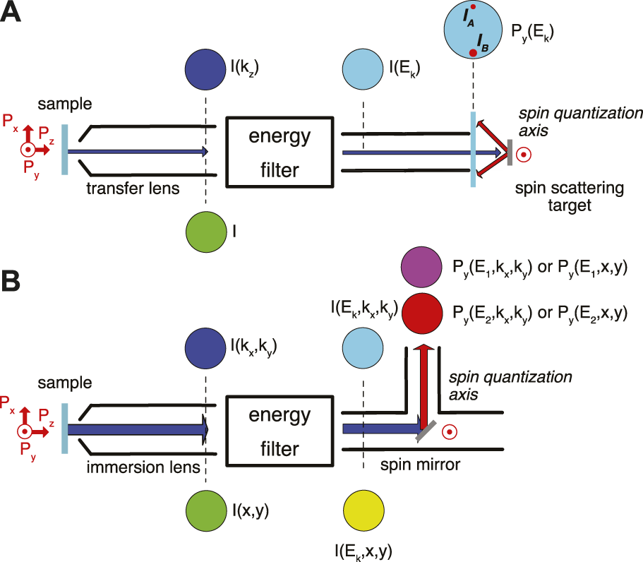
Spin detection schemes: (A) Single-channel spin detector. A narrow spin-polarized electron beam is guided by a transport optics to an energy filter. The energy-filtered beam at the scattering energy Es is diffracted at the target crystal with a spin quantization axis along y. The spin polarization component Py is measured via the spot intensity difference of two symmetrically diffracted beams, IA and IB, spanning the diffraction plane (according to Eq. 2). This is the SPLEED spin detection scheme. (B) Imaging spin filter. A wide-angle spin-polarized electron beam is guided by an immersion optics to an imaging energy filter. The image at its exit is reflected at a target crystal under 45°, which again defines the spin quantization axis along y via spin-orbit coupling. The spin polarization component Py is now determined as a difference of images (I (E1, kx, ky), I (E2, kx, ky)) taken at two different scattering energies (E1, E2) (details see text).
Later it was discovered that low-energy scattering of electrons from a solid single-crystal surface can also exhibit spin-dependent scattering effects, provided there is sufficient spin-orbit coupling in the electronic structure of a solid, as e.g., in tungsten (W). A corresponding spin detector employing a scattering at an energy of Ek ∼ 104 eV from a W (001) surface was introduced by Kirschner et al. As it involves a low-energy electron diffraction (LEED) principle (Figure 1A), it was termed SPLEED (spin-polarized LEED) detector [18]. The spin polarization component is determined from measuring the intensity difference of equivalent diffraction beams (intensity asymmetry), which define a scattering plane. The spin quantization axis is perpendicular to this scattering plane. For the SPLEED detector the spin-sensitive beams belong to the so-called {2, 0} family of LEED beams from the W (001) surface [19]. The spin polarization along y is calculated from these two beams IA and IB according to
with Seff denoting the effective spin sensitivity factor, i.e., the effective intensity difference which results in 100% spin polarization.
In the beginning of the 1990s there was the first introduction of a spin-detection principle using a single-crystal ferromagnet [20–22]. The scattering of spin-polarized electrons from a ferromagnetic Fe surface exploits the exchange interaction, whereby the quantization axis is given by the orientation of the magnetization . If we assume a beam spin-polarized along this direction will thus create an “up-down asymmetry” upon scattering off the ferromagnetic detector crystal. It involves even lower energies (Ek ∼ 12 eV), which defines the name very low energy electron diffraction (VLEED) for this type of detector. A certain improvement of the detector performance was achieved by oxidized Fe [23, 24] or Co scattering targets [25].
3 Advent of 2D spin detection and mapping schemes
3.1 The “spin filter” principle
Up to this point we have only considered single channel spin analyzers, i.e., one confined beam of electrons is analyzed at a time (see Figure 1A). As a consequence, the spin dependence e.g., as a function of kinetic energy must be measured by taking individual spin measurements for each value Ek–a very time-consuming and thus slow process. This situation changed only at after 2011, when the first parallel spin detection scheme was demonstrated in a photoemission experiment [26]. It used the energy dispersion and two-dimensional (2D) imaging capabilities of modern photoelectron spectrometers. In a 2D scheme, the electrons do not impinge normal to a W (001) surface, but rather at 45° making the crystal in fact to act as a mirroring spin filter (Figure 1B) (note, however, that the underlying physical mechanism of the spin mirror is still spin-dependent scattering based on spin-orbit coupling). The result of the spin filtering process is a 2D map of recorded on an imaging detector. The spin polarization is calculated from comparing two images taken at different scattering energies with high (H) and low (L) spin sensitivity, i.e., EH = 26.5 eV and EL = 30.5 eV for a W (001) spin filter [27, 28]. By combining this type of detector with a energy-filtered full-field photoelectron microscope, the full power of the parallel spin detection could be unleashed [29], as discussed below. Introducing with Au-passivated Ir (001) an even more advanced spin mirror based on spin-orbit coupling [30], the spin-detection efficiency and its long-term stability could be further improved to the current state-of-the-art [31].
3.2 Experimental realization of a spin-polarized 2D imaging device
Today’s state-of-the-art in condensed matter and surface physics studies may be seen in the momentum microscope, like the one sketched in Figure 2. A central part is an immersion lens objective, which uses the emitted photoelectrons to form a high-resolution real-space image of a defined surface area of the sample I (x, y) on the image plane of the lens system [32]. The immersion lens system may also include an additional “Fourier transform” lens, the task of which is to convert from the lateral distribution I (x, y) → I (θ, ϕ) into an angular distribution, with (θ, ϕ) denoting the emission angles of the electrons with respect to the surface normal . In case of a single-crystal surface, this quantity may actually be converted into I (kx, ky), with (kx, ky) denoting the in-plane components of the electrons momentum vector in the crystal. Either of these two images is then fed into the imaging energy analyzer (DHA) where it undergoes energy selection, e.g., I (x, y) ⇒ I (Ek, x, y), i.e., at the exit of the DHA we obtain an image with a defined kinetic energy Ek. This image is then accelerated and magnified by a set of projection lenses onto an image detector (usually a multichannel plate for amplification purposes followed by a fluorescent screen). From there the image is captured, e.g., by a CCD camera.
FIGURE 2
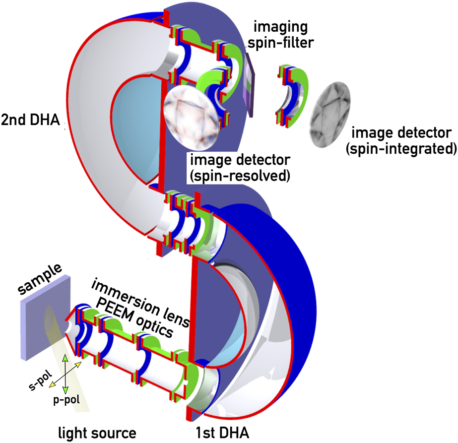
Layout of a spin-resolved momentum microscope. The core part is formed by an energy-filtering photoemission electron microscope featuring a double-hemispherical (DHA) energy analyzer arrangement. The immersion lens forms a two-dimensional image I (x, y) of the electrons emitted from the sample and transfers them into DHA. At the exit of the DHA the energy-filtered image is either directed to an imaging detector (straight path) or to a removable spin mirror, deflecting the beam by 90° into a second imaging detector. The light exciting the photoelectrons comes either from a laboratory source or a synchrotron beamline.
In case of a straight transfer through the projection optics we obtain regular intensity images on the detector. This will be either a real-space intensity map I (x, y) of the surface, or a angular distribution image I (θ, ϕ) which then corresponds to a cut through the momentum space of the crystal (Fermi surface mapping). The spin detecting unit is oriented at 90° to the exit trajectory line from the DHA and can be accessed by inserting the spin filter crystal into the electron path at 45°. The spin sensitive axis is perpendicular to the scattering plane, i.e., Py. As mentioned above the spin polarization is determined by comparing two images recorded at slightly different scattering energies, as mentioned already above [27, 28]. The same procedure is used to obtain either lateral P (Ek, x, y) or momentum space P (Ek, kx, ky) spin polarization maps.
The spin-resolved momentum microscope therefore provides us with a wide variety of experimental capabilities depending on the operation conditions. A laboratory photon source enables the two basic modes:
• imaging of spin textures in real space (e.g., magnetic domains and domain walls)
• imaging of spin textures in momentum space (spin-resolved band and Fermi surfaces)
Light from a synchrotron source expands the experimental capabilities of momentum microscopy due to a wide range of a tunable photon energy and a selectable light polarization. This enables a wide variety of chemical, electronic and magnetic studies in spectro microscopy. In addition, synchrotron radiation also provides a pulsed time structure in the picosecond regime which also enables time-resolved pump-probe experiments on this time scale.
4 State-of-the-art imaging of spin-polarized electronic states in condensed matter systems
The main strength of the new generation of 2D imaging spin detectors is the analysis of many parallel electron beams or entire images. In addition, the performance and service life of these detectors is significantly improved as compared to the first generation devices. It is therefore perfectly suited for full-field imaging experiments and thereby opens a novel dimension in spin-resolved spectroscopy and microscopy studies since 2011. This may address real space, momentum space, or even temporal aspects.
4.1 Spin-polarized electrons in real space
The first example addresses a real space imaging of the domain structure in a magnetic system–Fe3O4(001). Magnetite is a ferrimagnet with an inverse spinel structure, with oxygen atoms forming a face centered cubic (fcc) lattice at room temperature. It is also characterized by a temperature-dependent phase transition, the Verwey transition [33]. Upon lowering the temperature the crystal undergoes a change from an fcc to a monoclinic crystal structure, which is also accompanied by a type of metal-insulator transition with an considerable increase in resistivity. The images in Figure 3 have been acquired via by a gas discharge laboratory light source (ℏω = 21.2 eV), and depict the spin polarization component Py of the secondary electrons in an interval of ΔE ∼ 0.5 eV just above the vacuum level. It is important to point out that a magnetic system already in it is ground state is inherently spin-polarized due to the exchange interaction, and usually also forms a pattern of homogeneously magnetized and spin-oriented areas (so-called domain structure), which describes the spin texture in real space.
FIGURE 3
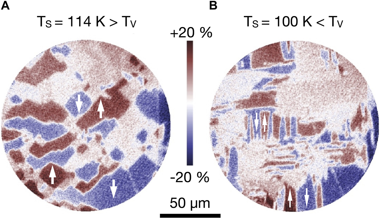
Domain structures in Magnetite Fe3O4(001) above (A) and below the Verwey temperature TV(B). The spin polarization contrast is color coded from −20% (blue) to +20% (red), with the spin quantization axis oriented along y (vertical). Domains with a magnetization perpendicular to y exhibit no spin polarization contrast and show up as white areas. Arrows show the spin orientation in some domains. Adapted from [33], licensed CC-BY-4.0.
The domain pattern in the cubic phase above the Verwey temperature TV (Figure 3A) exhibits rather large domains and quite irregular shapes. A closer analysis yields that the cubic magnetic anisotropy aligns the magnetization (and thus the spin polarization) along the in-plane 001 axes. More specifically, the domains in (Figure 3A) are oriented along the [010] and directions (up and down arrows). The domains magnetized along [100] and have a spin polarization component Px which is orthogonal to the spin quantization axis of the detector, hence they appear all in white in the image. The boundaries between the domains are either 180° magnetic domain walls, between blue and red regions, or 90° walls between the colored and the white areas.
The domain pattern changes significantly when going below the Verwey transition (Figure 3B). This is due to the change of the crystal structure into a monoclinic phase. This affects also the magnetic anisotropy making it 10-fold stronger and uniaxial, rendering the crystalline c-axis as easy axis for the magnetization. This process of forming monoclinic crystallites should happen for all three directions in space. However, c-axis crystallites oriented perpendicular to the surface ([001]) will be magnetically avoided, as the shape anisotropy drives the magnetization into the surface plane for energy reasons. As a result, the magnetization selects monoclinic orientations along [100] and [010]. In the spin-polarization images with Py we are therefore again sensitive to magnetization directions [010] and . The shape of the domains is more irregular as in Figure 3A, however, with a certain preference for elongated domains along the y-axis.
This example illustrates the power of the technique momentum microscopy to resolve details of the spin texture in real space.
4.2 Spin-polarized electrons in momentum space
The second example addresses the investigation of spin textures in momentum space, i.e., directly in the electronic structure of a material. If the material is not a ferromagnet, there is no ground-state spin polarization neither in real nor momentum space. However, most materials are also subject to spin-orbit coupling, the second spin-dependent interaction. Together with symmetry and topology aspects, spin-orbit coupling can therefore lead to characteristic spin textures in momentum space. The finding of unusual quantum transport effects [34] has started a wealth of studies on topological and two-dimension materials.
In order to first illustrate the general measurement procedure of momentum-space microscopy, we take the case of a two-dimensional transition metal dichalcogenide, nickel ditelluride NiTe2 and neglect the spin for the moment. NiTe2 has a trigonal crystal structure leading to a hexagonal Brillouin zone (Figure 4D), with corresponding surface Brillouin zones. Being a quantum material, NiTe2 also exhibits Dirac cones at the surface due to broken inversion symmetry at the surface. The measurements are taken for different photon energies ℏω and result in 3-dimensional intensity distributions I (EB, kx, ky)) as a function of binding energy EB and the emission angles, which are converted into the momentum vector components kx and ky [35]. Cuts at the Fermi level EF are indicated in Figures 4A–C for three different photon energies. In the bulk Brillouin zone these cuts lie on curved surfaces which mark the accessible kz range at each photon energy, and these surfaces move along the kz axis with increasing ℏω. In this way, the entire bulk Brillouin zone along ΓDAD and also the neighboring ones can be mapped in detail. The data can then be plotted as I (k‖, kz), whereby k‖ denotes the parallel wave vector in the kx, ky plane, i.e., resulting into intensity maps along the (Figure 4E) and along the (Figure 4F) lines in the surface Brillouin zones. These data then permit a direct comparison to band structures, with the dark blue lines marking the calculated bulk electronic states [36].
FIGURE 4
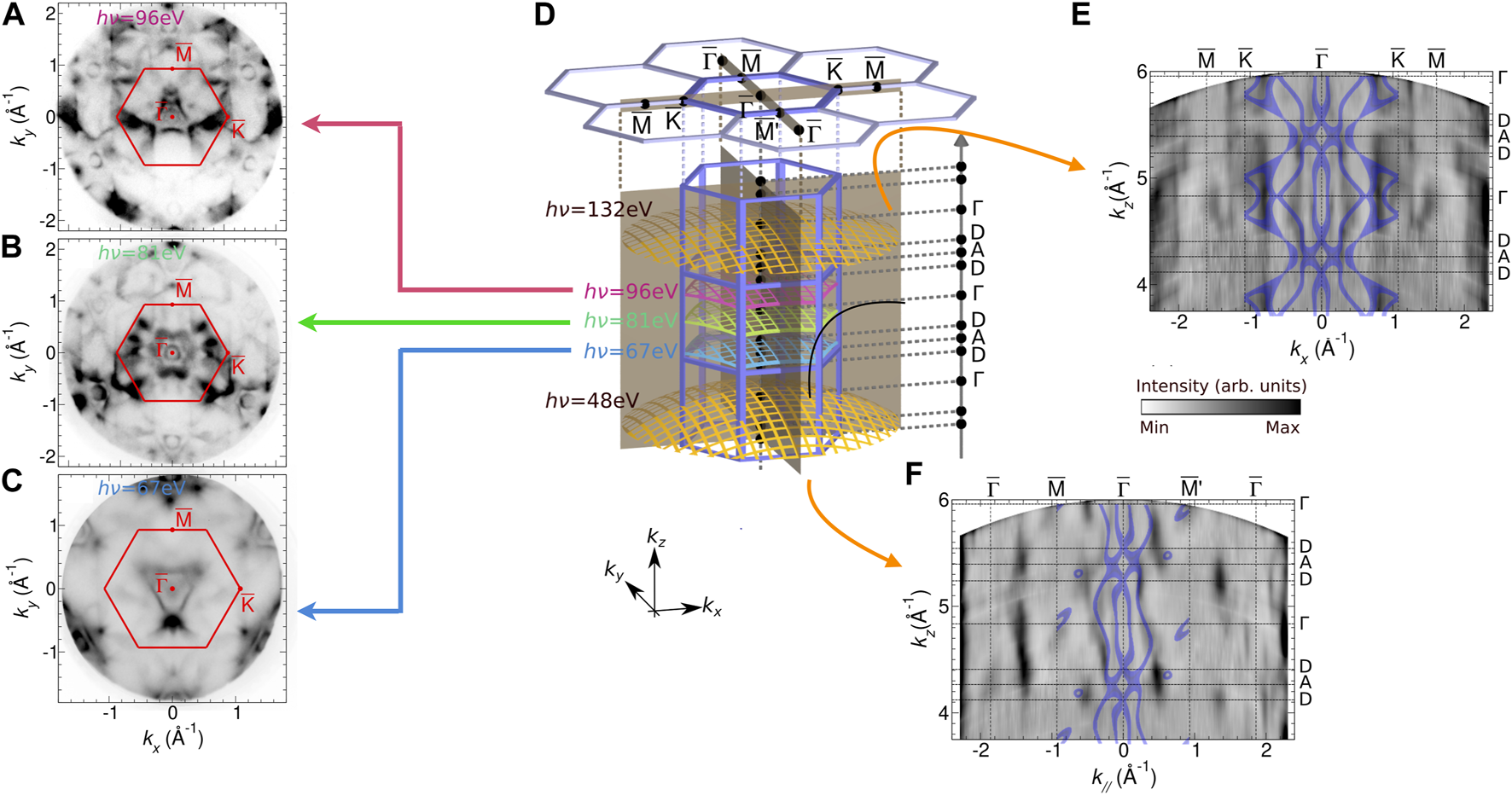
General measurement procedure in momentum microscopy. First, three-dimensional intensity distributions I (E, kx, ky) are recorded for various photon energies ℏω. Panels (A–C) correspond to two-dimensional slices of these distributions at the Fermi energy, i.e., I (EF, kx, ky). In momentum space each phonon energy corresponds to a distinct curved surface through the bulk Brillouin zone [panel (D)], as the wave vector component kz increases with the photon energy. The data sets at different ℏω values then yield a three-dimensional distribution I (kx, ky, kz) within the Brillouin zone. The images show cuts along kz in the (E) and the (F) symmetry direction. Adapted from [35], licensed CC-BY-4.0.
The above procedure can be used in a very similar manner to analyze the dispersion of spin-polarized electronic states. As mentioned above we have to pass the intensity distributions I (E, kx, ky) through the imaging spin detector and compare the distributions at two different scattering energies. Spin-resolved momentum microscopy data recorded for NiTe2 exhibit a clear spin-polarization of the surface Dirac cones. (a full discussion of the spin-resolved data from this system a subject to a forthcoming publication [36]).
The results for a W (110) crystal are shown in Figure 5. The studies had the aim to elucidate the anisotropic spin mixing in this material [37]. Although tungsten is considered as a normal metal, it also has a strong spin-orbit coupling, which makes it one of the most efficient materials for charge-to-spin current conversion [38] exploited in the spin Hall magnetoresistance. It is also considered a Dirac material, which is characterized by regions of linear dispersion in the electronic structure. This topological property manifests as Dirac cones at specific locations in the Brillouin zone (Figure 5C). The combination of a two-fold surface and time-reversal symmetry allows only for a spin polarization within the surface plane, i.e., Px ≠ 0, Py ≠ 0, if the photoelectrons are excited by linearly polarized light.
FIGURE 5
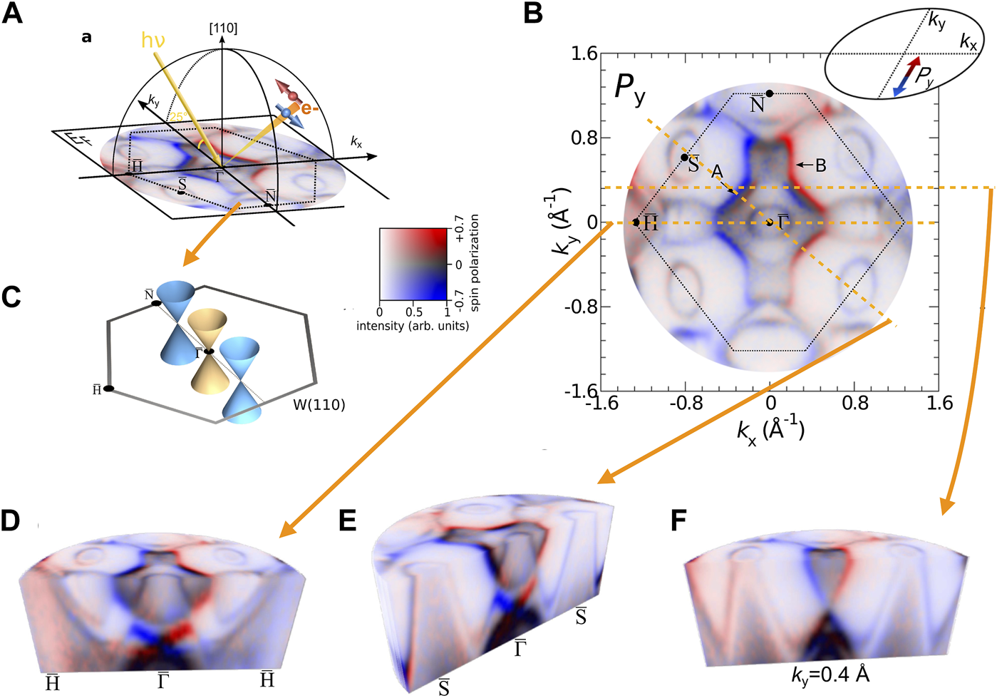
Spin-polarized momentum microscopy on W (110). (A) Sketch of the experimental geometry with indication of the surface Brillouin zone and photoemission configuration, overlaying a 2D spin-polarization map taken at the Fermi energy EF. The same map is displayed in more detail in (B) and shows the Py spin component, color-coded in the red (spin up)–blue (spin-down) scheme. (C) Surface Brillouin zone with the position of three Dirac cones. (D–F) Three-dimensional spin-polarization distribution P (EB, kx, kz) taken in the binding energy range between EB = EF and EB = EF–1.7 eV. Cuts through this distribution show the dispersion of spin-polarized states along the (D), (E), and parallel to the kx axis at (F). The cuts reveal regions of linear dispersions E(k), which are a consequence of the three Dirac cones at and included in (C). Adapted from [37], licensed CC-BY-4.0.
The results in Figure 5 have been taken at a photon energy ℏω = 50 eV and map the three-dimensional distribution of the spin polarization component Py (indicated by the arrows and the color code in panel (a)). The vertical cuts covering the binding energies between EF and EF − 1.7 eV clearly reveal linearly dispersing bands at (d,e) and also in (f). These result from vertical cuts through the Dirac cones aligned along the line. All three are located in a spin-orbit-induced bulk band gap, and are caused by d-orbital derived surface states [39]. They also appear as circular structures in the 2D spin-polarization map at EF in panel (b). This behavior points to a non-trivial topological character in the material tungsten, which may be considered as a topological crystalline material where the Dirac cones at the (110) surface are protected by the mirror symmetry.
A closer inspection also yields that the spin direction (color-code red/blue) differs in the various branches of the cone states. The most prominent effect is observed for the X-shaped structure around the -point (5d,e) which can be traced back to surface resonances stemming from d-type states. The linear bands at cross at EB = EF − 1.25 eV (Dirac point), whereas those at cross at EB = EF − 0.75 eV (Dirac point). The spin-polarization vector is locked to the momentum vector , leading to a rotation of around the Dirac cones. This explains the changes between blue ⇔ red on opposite sides of the Γ-point. The Py distribution in Figure 5B also reveals a Rashba-type spin splitting around (marked by “A”).
Similar weaker spin-polarized cone structures show up at the and points, resulting in the circular features at this points in Figure 5B). The spin splitting at the -points is due to a small Rashba-type mechanism in these surface states. Similar data (not shown here) have been taken for the Px spin polarization distribution [37]. The full spin-polarization map Px,y (kx, ky) yields two main findings: First, it shows that the spin polarization vector is locally aligned tangentially to the Fermi surface contour. This behavior is reminding one of the spin warping present in some topological insulators. Second, along spin quantization axis (SQA), which is oriented perpendicular to the crystal’s mirror plane, the spin polarization values Px are substantially smaller than for Py. Further theoretical studies show that the reason lies in the (spin mixing), which is relatively uniform across the Fermi surface in the case of SQA‖y, with large spin mixing only appearing at specific locations. If the spin quantization axis is aligned along x (SQA‖x), large areas of the surface Brillouin zone actually exhibit a full spin mixing in the electronic states [37]. An electron that is scattered into such states will consequently experience a high spin-flip probability, i.e., a high spin decoherence. These results prove the existence of an anisotropic spin mixing, which may have a considerable influence on the performance of spin-electronic or quantum computing devices.
4.3 Moving momentum microscopy into the time domain
So far, we have only considered spin-polarized systems in a steady-state situation. The challenge that is still out there is the combination of time- and spin-resolution in a single experiment. This will be necessary to be able to address dynamic electronic and spin-dependent processes on potentially ultrafast time scales, i.e., in the femtosecond regime. The general principle of such a momentum microscopy experiment follows the “two-colour pump-probe” scheme, i.e., in the first step a light pulse for the excitation of the system is needed, which usually is provided by a femtosecond laser system (Ti-sapphire) operating in the near infrared region λ ∼ 800 nm. The respective photon energy of ℏω ∼ 1.6 eV is usually not sufficient to directly excite photoelectrons above the vacuum level. In a subsequent step the excited state of the system is then probed by a time-delayed light pulse of higher photon energy. The time delay is such as to probe photoelectrons from the system in the excited (transient) state. So far, time-resolved momentum microscopy without spin-resolution has been realized in several cases using either ultrashort light pulses from a free-electron laser source [40, 41] or a higher harmonic generation (HHG) light source [42]. In both cases probing light pulses with widths in the 100fs regime are used.
The pulsed nature of the probe radiation introduces a certain detection efficiency problem in the momentum microscopy as compared to the normal operation. This is caused by the pulse pattern with a pulse width of the order of Δt ∼ 100fs and a pulse repetition rate typically in the 1 MHz regime. In order to increase the detection efficiency, therefore a modified momentum microscopy principle has been developed–the time-of-flight (ToF) momentum microscopy [43]. In this case, one exploits the kinetic energy differences in an electron spectrum. Electrons of different kinetic energy have different propagation velocities. The energy filtering is then performed by means of a “drift tube”, which translates the electron’s velocity into an arrival time on a detector. As the photoelectrons at the sample are all excited at the same time by the ultrashort probe pulse, the faster (high kinetic energy) ones will arrive earlier at the detector as the slower ones (low kinetic energy). In order to make use of this temporal dispersion, the image detector must offer a time-resolution, too. This time resolution is achieved by delayline detectors (DLD) [44]. This is a two-dimensional detector, which can record the location and the arrival time of each electron, i.e., one actually obtains a three-dimensional data set I (kx, ky, t), which can then be converted into I (kx, ky, E). This approach works best, if the repetition rate of the pulses is in the low MHz-regime, as the electron distributions resulting from subsequent pulses should not overlap.
This approach of a time-resolved ToF momentum microscopy has been involved to obtain the results displayed in Figure 6. The data have been recorded in a specific pump-probe set-up developed at the free-electron laser facility FLASH (Hamburg) with a 4-quadrant DLD. The sample is a 2H-WSe2 crystal pumped by a laser pulse of λ = 775 nm. This wavelength is sufficient to excite the A exciton transition in the valleys at the and points in this material. The transient excited state in the entire Brillouin zone is subsequently probed by ℏω = 36.5 eV laser pulses from FLASH. The crystal 2H-WSe2 is another 2D semiconducting transition-metal dichalcogenide. It has a hexagonal crystal structure and the bulk and surface Brillouin zones together with some high-symmetry points are displayed in Figure 6A. WSe2 has a band gap separating the valence and conduction bands. The intensity distribution in Figure 6B refers to the situation before the pump pulse arrives, i.e., the “ground state” of the system. The intensity is color-coded and reflects several features located at the state (center of the Brillouin zone). In addition, one can discern a hexagonal ring of additional weaker features (dips) located at the and points.
FIGURE 6
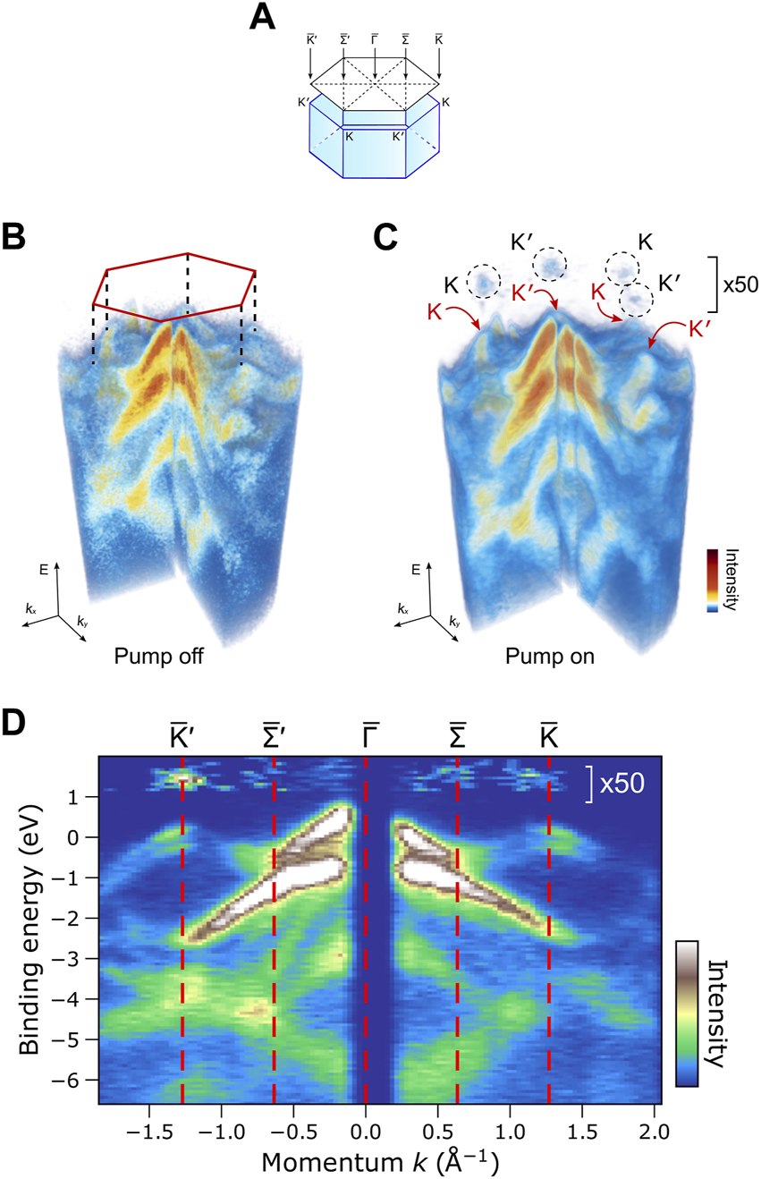
Time-resolved momentum microscopy on WSe2 layers. (A) Bulk Brillouin zone of a 2H-WSe2 crystal with indication of the surface Brillouin zone, marking the surface high symmetry points. (B) Three-dimensional intensity distribution I (E, kx, ky of the system in the ground state upon excitation with a photon energy of ℏω = 36.5 eV. (C) Intensity distribution after optical excitation with 775 nm pulses from the free electron laser. The resulting transient electron densities in the and valleys are marked by circles. (D) Vertical cuts along and , exhibiting a clear transient intensity at . Adapted from [40], licensed CC-BY-4.0.
The experiment then follows the electron dynamics via the population and depopulation of the and conduction band valleys as a function of time. A snapshot at a delay time of ∼ 100fs between pump and probe pulses is given in Figure 6C. The photoemission intensity distribution reveals a similar pattern as in Figure 6C, but also additional signatures corresponding to the excited electrons in the above mentioned and valleys (encircled). This can also be seen in the vertical cuts (Figure 6D) along and , exhibiting a clear transient intensity at and a weaker one at .
Following the further time evolution after the pump pulse shows that these transient electron populations decay with a time constant of fs in a complex process into the and band valleys, which reach their maximum occupation about 60fs after that of the valleys. From there, the populations at (, ) decay into the ground state again with a time scale of about fs. For more details see Ref. [40].
4.4 The challenge to address spin-polarized electrons in the time domain
This previous result illustrates the power of time-resolved momentum microscopy to detail the physical processes and time scales in a complex electronic system. The long-term perspective will include also spin detection in this approach, enabling the study of magnetic materials and exploring the spin dynamics processes leading to ultrafast demagnetization after optical excitation and discerning the various spin-dependent mechanisms governing the behavior on ultrashort time scales throughout the entire Brillouin zone.
Using a “conventional” hemispherical photoelectron spectrometer with a spin detector allows one to analyze at least selected directions in momentum space. Such an experiment has been performed recently [45], addressing the spin polarization of electrons from Fe transmitted through a Au overlayer. In this case, the sample was a Fe (001) film covered by Au films of various thicknesses. The electrons were excited by an ultrashort pump light pulse (Δt ∼ 20fs, λ = 800 nm), leading in Fe to a transient non-equilibrium distribution above the Fermi level and an ultrafast demagnetization. One mechanism of this demagnetization is the propagation of electrons out of the excited region (laterally and vertically), which takes place via so-called superdiffusive spin currents [46, 47]. The presence of this superdiffusive currents has been already proven by several magnetooptic techniques [48, 49]. In Fe, the microscopic mechanism involves different propagation velocities of majority and minority spin electrons [47]. As a consequence, the electrons moving from Fe into the Au layer are highly spin-polarized and of majority spin character. The probe pulse of ℏω = 21 eV is obtained by sending part of the pump pulse through a higher harmonic generation (HHG) scheme. The photoemission signal at the Fermi level EF stems mainly from the gold overlayer and has a clear majority spin character, the magnitude and decay time (of the order of several 100 fs) depends on the gold film thickness. As mentioned above, we expect a more detailed picture of the ultrafast spin dynamics in condensed matter systems from future spin-resolved momentum microscopy.
5 Moving to higher energies with spin-polarized electrons?
This contribution focuses on low-energy spin-polarized electrons, which have delivered a plethora of relevant and interesting results during the last decades. Given the breathtaking development of light sources during the same time, one may ask the question, whether spin-polarized electrons of higher kinetic energy (Ek > 1 keV) can be generated and subsequently used for experiments. On the one hand, the new generation of powerful femtosecond laser sources (and free-electron lasers) nowadays provides convenient access to higher harmonic generation (HHG) radiation [50], which may even cover the entire range up to ℏω ∼ 1 keV–maybe with somewhat limited photon flux, though. One step on this way is the VEGA laser system installed within the JuSPARC project in Juelich [51], which provides a peak energy per pulse of almost E ∼ 40 mJ with a pulse duration of Δt ∼ 30 fs. Recent experiments with synchrotron radiation have shown that even at high kinetic energies of up to Ek ∼ 5 keV spin-polarized electrons can be generated and spin-analyzed [52]. This may open the avenue for higher energy scattering and diffraction experiments with spin-polarized electrons, if the intensity of the electron beam before scattering can be made high enough.
On the other hand, such an above powerful laser source may be also employed for plasma acceleration of charged particles. In this case, the peak energy needs to be tightly focused down into a dedicated gas cell to start a laser plasma acceleration process. In order to increase the interaction, the light pulses may even be compressed, leading to shorter pulses and higher time resolution in the experiment. However, so far only theoretical predictions are available [53]. Nevertheless, the results for a laser wakefield acceleration scheme predict kinetic energies of electrons in the MeV regime, which would then open up a new pathway for experiments with high-energy electrons.
6 Conclusion
In this contribution we have tried to sketch the evolution of low-energy spin-polarized electron physics, which has come a long way over more than five decades. Nowadays we are in a position to control and exploit spin-polarized electrons and electron beams in a wide variety of spectroscopy and microscopy experiments–mostly applied to problems in surface physics. State of the art spin-resolved momentum microscopy combines spectroscopic and microscopic facets in a unique manner for the study and understanding of a wide variety of solid state systems, enabling unparalleled access to the new field of topology. The inclusion of ultimate time-resolution will extend the capabilities also in the time-domain.
Statements
Data availability statement
Publicly available datasets were analyzed in this study. This data can be found here: All existing data are taken from articles they are referred to in the publication list of the article.
Author contributions
CT: Data curation, Formal Analysis, Investigation, Visualization, Writing–review and editing. Y-JC: Data curation, Formal Analysis, Investigation, Visualization, Writing–review and editing. CS: Conceptualization, Writing–original draft, Writing–review and editing.
Funding
The author(s) declare financial support was received for the research, authorship, and/or publication of this article. This work was financially supported in part by the BMBF (grant No. 05K19PGA).
Acknowledgments
We would like to acknowledge the collaboration with Kenta Hagiwara (now IMS, Japan) and Xin L. Tan (now NTNU, Norway). Fruitful discussions with S. Suga, V. Feyer, R. Adam, and M. Büscher are gratefully acknowledged.
Conflict of interest
Authors CT, Y-JC, and CS were employed by Forschungszentrum Jülich GmbH.
Publisher’s note
All claims expressed in this article are solely those of the authors and do not necessarily represent those of their affiliated organizations, or those of the publisher, the editors and the reviewers. Any product that may be evaluated in this article, or claim that may be made by its manufacturer, is not guaranteed or endorsed by the publisher.
References
1.
Messiah A . Quantum mechanics. Dover Publications (1999).
2.
Patterson JD Bailey BC . Solid-state physics. Berlin: Springer (2007).
3.
White R . Quantum theory of magnetism. In: Springer series in solid-state sciences. 2nd ed. Berlin: Springer-Verlag (1983).
4.
Nordling C Sokolowski E Siegbahn K . Precision method for obtaining absolute values of atomic binding energies. Phys Rev (1957) 105:1676–7. 10.1103/physrev.105.1676
5.
Lindau I Pianetta P Doniach S Spicer WE . X-ray photoemission spectroscopy. Nature (1974) 250:214–5. 10.1038/250214a0
6.
Feuerbacher B Fitton B Willis R . Photoemission and the electronic properties of surfaces. New York: Wiley (1978).
7.
Siegbahn K . Electron spectroscopy for atoms, molecules, and condensed matter. Rev Mod Phys (1982) 54:709–28. 10.1103/revmodphys.54.709
8.
Hüfner S . Photoemission spectroscopy. In: Springer series in solid state physics, 82. Berlin: Springer-Verlag (1995).
9.
Meier F Zakharchenya B Modern problems in condensed matter sciences. Amsterdam: North-Holland: Optical orientation (1984).
10.
Meier F . Spin polarized photoemission by optical orientation in semiconductors. In: FederR, editor. Polarized electrons in surface physics. Singapore: World Scientific (1985).
11.
Pierce D Meier F . Photoemission of spin-polarized electrons from GaAs. Phys Rev B (1976) 13:5484–500. 10.1103/physrevb.13.5484
12.
Alley R Aoyagi H Clendenin J Frisch J Garden C Hoyt E et al The Stanford linear accelerator polarized electron source. Nucl Instr Methods Phys Res Section A: Acc Spectrometers, Detectors Associated Equipment (1995) 365:1–27. 10.1016/0168-9002(95)00450-5
13.
Aulenbacher K Nachtigall C Andresen H Bermuth J Dombo T Drescher P et al The MAMI source of polarized electrons. Nucl Instr Methods Phys Res Section A: Acc Spectrometers, Detectors Associated Equipment (1997) 391:498–506. 10.1016/s0168-9002(97)00528-7
14.
Mamaev YA Subashievf AV Yashin YP Ambrazhei AN Drouhin H-J Lampel G et al Spin polarized electron transport and emission from strained semiconductor heterostructures. In: Morán-LópezJL, editor. Physics of low dimensional systems. Boston, MA: Springer US (2001). p. 373–82.
15.
Jin X Ozdol B Yamamoto M Mano A Yamamoto N Takeda Y . Effect of crystal quality on performance of spin-polarized photocathode. Appl Phys Lett (2014) 105:203509. 10.1063/1.4902337
16.
Kessler J . Polarized electrons. 2nd ed. Berlin: Springer Series on Atoms and Plasmas (Springer-Verlag (1985).
17.
Kirschner J . Polarized electrons at surfaces, springer tracts in modern physics. Berlin: Springer-Verlag (1985).
18.
Kirschner J Feder R . Spin polarization in double diffraction of low-energy electrons from W(001): experiment and theory. Phys Rev Lett (1979) 42:1008–11. 10.1103/physrevlett.42.1008
19.
Kirschner J . Inelastic electron scattering by ferromagnets. In: FederR, editor. Polarized electrons in surface physics. Singapore: World Scientific (1985).
20.
Tillmann D Thiel R Kisker E . Very-low-energy spin-polarized electron diffraction from Fe(001). Z Phys B (1989) 77:1–2. 10.1007/bf01313611
21.
Jungblut R Roth C Hillebrecht FU Kisker E . Magnetic properties of Cr overlayers on Fe (invited). J Appl Phys (1991) 70:5923–8. 10.1063/1.350107
22.
Jungblut R Roth C Hillebrecht FU Kisker E . Spin-polarized electron spectroscopy as a combined chemical and magnetic probe. Surf Sci (1992) 269:615–21. 10.1016/0039-6028(92)91320-b
23.
Winkelmann A Hartung D Engelhard H Chiang CT Kirschner J . High efficiency electron spin polarization analyzer based on exchange scattering at Fe∕W(001). Rev Sci Instrum (2008) 79:083303. 10.1063/1.2949877
24.
Graf J Jozwiak C Schmid AK Hussain Z Lanzara A . Mapping the spin-dependent electron reflectivity of Fe and Co ferromagnetic thin films. Phys Rev B (2005) 71:144429. 10.1103/physrevb.71.144429
25.
Jozwiak C Graf J Lebedev G Andresen N Schmid AK Fedorov AV et al A high-efficiency spin-resolved photoemission spectrometer combining time-of-flight spectroscopy with exchange-scattering polarimetry. Rev Sci Instrum (2010) 81:053904. 10.1063/1.3427223
26.
Kolbe M Lushchyk P Petereit B Elmers HJ Schönhense G Oelsner A et al Highly efficient multichannel spin-polarization detection. Phys Rev Lett (2011) 107:207601. 10.1103/physrevlett.107.207601
27.
Tusche C Ellguth M Krasyuk A Winkelmann A Kutnyakhov D Lushchyk P et al Quantitative spin polarization analysis in photoelectron emission microscopy with an imaging spin filter. Ultramicroscopy (2013) 130:70–6. 10.1016/j.ultramic.2013.02.022
28.
Tusche C . Momentum microscopy. In: SugaSSekiyamaATuscheC, editors. Photoelectron spectroscopy. Springer series in surface sciences, 72. Berlin: Springer (2021).
29.
Tusche C Ellguth M Ünal AA Chiang C Winkelmann A Krasyuk A et al Spin resolved photoelectron microscopy using a two-dimensional spin-polarizing electron mirror. Appl Phys Lett (2011) 99:032505. 10.1063/1.3611648
30.
Kirschner J Giebels F Gollisch H Feder R . Spin-polarized electron scattering from pseudomorphic Au on Ir(001). Phys Rev B (2013) 88:125419. 10.1103/physrevb.88.125419
31.
Vasilyev D Tusche C Giebels F Gollisch H Feder R Kirschner J . Low-energy electron reflection from Au-passivated Ir(0 0 1) for application in imaging spin-filters. J Electron Spectr Rel Phen (2015) 199:10–8. 10.1016/j.elspec.2014.12.006
32.
Bauer E . Surface microscopy with low energy electrons. New York: Springer (2014).
33.
de la Figuera J Tusche C . The Verwey transition observed by spin-resolved photoemission electron microscopy. Appl Surf Sci (2017) 391:66–9. 10.1016/j.apsusc.2016.05.140
34.
Moore JE . The birth of topological insulators. Nature (2010) 464:194–8. 10.1038/nature08916
35.
Tusche C Hagiwara K Tan XL Chen Y-J Schneider CM . Exploring the mysteries of topology in quantum materials by spin-resolved spectroscopies. J Vac Sci Techn B (2023) 41:042201. 10.1116/6.0002707
36.
Hagiwara K Rüßmann P Tan XL Chen Y-J Ueno K Feyer V et al Link between weyl-fermion chirality and spin texture (2022). arXiv:2205.15252 [cond-mat.mtrl-sci].
37.
Chen Y-J Hoffmann M Zimmermann B Bihlmayer G Blügel S Schneider CM et al Quantum spin mixing in Dirac materials. Comm Phys (2021) 4:179. 10.1038/s42005-021-00682-5
38.
Cho S Baek S-H Lee K-D Jo Y Park B-G . Large spin Hall magnetoresistance and its correlation to the spin-orbit torque in W/CoFeB/MgO structures. Sci Rep (2015) 5:14668. 10.1038/srep14668
39.
Zhang T Jiang Y Song Z Huang H He Y Fang Z et al Catalogue of topological electronic materials. Nature (2019) 566:475–9. 10.1038/s41586-019-0944-6
40.
Kutnyakhov D Xian RP Dendzik M Heber M Pressacco F Agustsson SY et al licensed under a Creative Commons Attribution (CC BY) license. Rev Sci Instrum (2020) 91:013109. 10.1063/1.5118777
41.
Baumgärtner K Reuner M Metzger C Kutnyakhov D Heber M Pressacco F et al Ultrafast orbital tomography of a pentacene film using time-resolved momentum microscopy at a FEL. Nat Comm (2022) 13:2741. 10.1038/s41467-022-30404-6
42.
Keunecke M Möller C Schmitt D Nolte H Jansen GSM Reutzel M et al Time-resolved momentum microscopy with a 1 MHz high-harmonic extreme ultraviolet beamline. Rev Sci Instrum (2020) 91:063905. 10.1063/5.0006531
43.
Maklar J Dong S Beaulieu S Pincelli T Dendzik M Windsor YW et al A quantitative comparison of time-of-flight momentum microscopes and hemispherical analyzers for time- and angle-resolved photoemission spectroscopy experiments. Rev Sci Instrum (2020) 91:123112. 10.1063/5.0024493
44.
Oelsner A Schmidt O Schicketanz M Mj K Schönhense G Mergel V et al Microspectroscopy and imaging using a delay line detector in time-of-flight photoemission microscopy. Rev Sci Instrum (2001) 72:3968–74. 10.1063/1.1405781
45.
Bühlmann K Saerens G Vaterlaus A Acremann Y . Detection of femtosecond spin injection into a thin gold layer by time and spin resolved photoemission. Scientific Rep (2020) 10:12632. 10.1038/s41598-020-69477-y
46.
Battiato M Carva K Oppeneer PM . Superdiffusive spin transport as a mechanism of ultrafast demagnetization. Phys Rev Lett (2010) 105:027203. 10.1103/physrevlett.105.027203
47.
Battiato M Carva K Oppeneer PM . Theory of laser-induced ultrafast superdiffusive spin transport in layered heterostructures. Phys Rev B (2012) 86:024404. 10.1103/physrevb.86.024404
48.
Melnikov A Razdolski I Wehling TO Papaioannou ET Roddatis V Fumagalli P et al Ultrafast transport of laser-excited spin-polarized carriers inAu/Fe/MgO(001). Phys Rev Lett (2011) 107:076601. 10.1103/physrevlett.107.076601
49.
Rudolf D La-O-Vorakiat C Battiato M Adam R Shaw JM Turgut E et al Ultrafast magnetization enhancement in metallic multilayers driven by superdiffusive spin current. Nat Commun (2012) 3:1037. 10.1038/ncomms2029
50.
Popmintchev D Hernández-García C Dollar F Mancuso C Pérez-Hernández JA Chen M-C et al Ultraviolet surprise: efficient soft x-ray high-harmonic generation in multiply ionized plasmas. Science (2015) 350:1225–31. 10.1126/science.aac9755
51.
Adam R Tusche C Hützen A Wiemann C Chen Y-J Büscher M et al JuSPARC - the jülich short-pulsed particle and radiation center. J large-scale Res Facil (2020) 6:A138. 10.17815/jlsrf-6-174
52.
Schmitt M Kirilmaz O Chernov S Babenkov S Vasilyev D Fedchenko O et al Bulk spin polarization of magnetite from spin-resolved hard x-ray photoelectron spectroscopy. Phys Rev B (2021) 104:045129. 10.1103/physrevb.104.045129
53.
Chitgar Z . Optical control of laser-driven X-ray and XUV radiation sources. In: Veröffentlicht auf dem Publikationsserver der RWTH Aachen University. Aachen: Dissertation, RWTH Aachen University (2021).
Summary
Keywords
topological materials., spin polarization, spin-orbit coupling (SOC), exchange interaction, momentum microscopy, spin filter
Citation
Tusche C, Chen Y-J and Schneider CM (2024) Low-energy spin-polarized electrons: their role in surface physics. Front. Phys. 12:1349529. doi: 10.3389/fphy.2024.1349529
Received
04 December 2023
Accepted
19 January 2024
Published
07 February 2024
Volume
12 - 2024
Edited by
Theodore Peter Rakitzis, University of Crete, Greece
Reviewed by
Hans-Joachim Elmers, Johannes Gutenberg University Mainz, Germany
Thomas Heinzel, Heinrich Heine University of Düsseldorf, Germany
Updates
Copyright
© 2024 Tusche, Chen and Schneider.
This is an open-access article distributed under the terms of the Creative Commons Attribution License (CC BY). The use, distribution or reproduction in other forums is permitted, provided the original author(s) and the copyright owner(s) are credited and that the original publication in this journal is cited, in accordance with accepted academic practice. No use, distribution or reproduction is permitted which does not comply with these terms.
*Correspondence: Claus M. Schneider, c.m.schneider@fz-juelich.de
Disclaimer
All claims expressed in this article are solely those of the authors and do not necessarily represent those of their affiliated organizations, or those of the publisher, the editors and the reviewers. Any product that may be evaluated in this article or claim that may be made by its manufacturer is not guaranteed or endorsed by the publisher.