Abstract
The bandwidth of multimode W-type microstructured plastic optical fibers (mPOFs) is analyzed using the time-dependent power flow equation (TD PFE). The results demonstrate that increasing the wavelength enhances the bandwidth in W-type mPOFs, depending on the inner cladding width and the launch beam distribution width. We observed that bandwidth improves with thinner and shallower inner cladding, as well as a narrower centrally launched beam. This characterization aligns with the fibers’ effectiveness in increasing bandwidth, allowing for the customization of various W-type optical fibers for specific applications at different wavelengths.
1 Introduction
Optical fiber communication systems offer greater reliability and flexibility compared to wireless communication, serving as the backbone of modern telecommunication networks [1]. Microstructured optical fibers (MOFs) or photonic crystal fibers (PCFs), represent a specialized optical fiber technology designed for light guiding [2]. In certain types of PCFs, a high refractive index (RI) material, such as silica or polymer, is used as the base, with periodically distributed air holes. This hole pattern lowers the effective refractive index (RI) of the fiber cladding, allowing the optical fibers to guide light [2–7]. The cladding hole pattern design enables modifications to the refractive index (RI) profile of the optical fiber. PCFs demonstrate exceptional performance, as their microstructure offers increased flexibility for adjusting the cross-section during the design process. Various types of PCFs can be utilized for different applications [8–24]. The spacing between the cladding holes determines the numerical aperture (NA) of the fiber, typically around 0.5 to 0.6 [25–27]. Additionally, certain PCFs incorporate heavy metal oxide glass fibers [28] and liquid-filled hollow-core fibers for specialized applications [29]. High NA PCFs have also exhibited excellent resolution in lensless focusing [30].
PCFs offer outstanding bandwidth performance and versatility, making them ideal for sensing and transmission applications. The propagation characteristics of PCFs are essential for their practical applications and are affected by modal dispersion, mode attenuation, mode coupling. Mode coupling primarily arises from light scattering caused by intrinsic perturbations within the fiber. One of the most effective methods for predicting mode propagation characteristics of multimode optical fibers involves using the PFE [31–39]. This study seeks to investigate the impact of wavelength on the fiber’s bandwidth across different configurations of multimode W-type mPOFs, taking into account variations in the intermediate layer width and the distribution of the centrally launched beam.
2 W-type mPOF
The effective refractive index (RI) profile of a chosen optical fiber layer can be modified by altering the geometric parameters dq, dp and Λ (Figures 1A). We employed the TD PFE to simulate this system (Figure 1B).
FIGURE 1
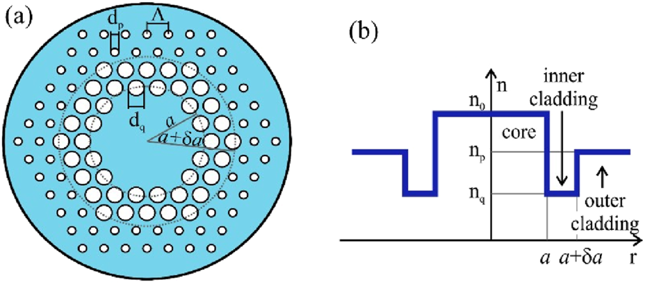
(A) The cross section of the W-type mPOF. Λ is the pitch, dq and dp are the diameters of inner and outer cladding air-holes, respectively. (B) The RI of the referent W-type mPOF.
3 TD PFE
The TD PFE for multimode optical fibers is given as [31, 35]:where t is time; is power distribution over propagation angle, length, and time; is modal delay; is the coupling coefficient; and is the attenuation [31, 35]. One should note that the condition of validity of the model proposed in this work is that guiding modes can be treated as a modal continuum. This is the case with all types of multimode optical fibers, such as a W-type mPOF investigated in this work. A more detailed explanation of the method for solving Equation 1 and calculating the bandwidth of W-type optical fibers can be found in our earlier publication [38].
W-type optical fiber (Figure 1) can be considered as a system of a SCq optical fiber and cladding, in which the angle is the critical angle for the guided modes–where . Similarly, the angle is the critical angle for the guided modes of a SCp optical fiber, where . The modes whose propagation angles are between and , where and , are leaky modes. Attenuation constants of leaky modes (Equation 2) are given as [35]:where = 2π/λ, a is the core radius and da is the width of the intermediate layer (inner cladding). The attenuation in this fiber can be expressed as [35]:
In this study, to the best of our knowledge, we are the first to explore how bandwidth in multimode W-type mPOFs can be improved by transitioning from smaller to larger wavelengths, taking into account various widths of the intermediate layer (Equation 3) and different FWHM of the centrally launched beam distribution. The findings could be useful in the design of W-type mPOFs for communication and sensing applications.
4 Numerical results and discussion
We examined the bandwidth of a multimode W-type mPOF with a solid core (Figure 1) at various wavelengths. Its effective V parameter is given as:where n0 is the RI of the core, nfsm is the effective RI of the cladding and [33]. The effective RI of the cladding n1≡nfsm, can be obtained from Equation 4, using the following equation [33]:with the fitting parameters Ai (i = 1–4) given as:where the coefficients ai0 to ai3 and bi1 to bi3 (i = 1–4) in Equations 5 and 6 are provided in our earlier works [36, 37].
The W-type mPOF was developed from the singly-clad (SC) mPOF, which we analyzed theoretically in our recent publication [39]. The SC mPOF had n0 = 1.492, diameter b = 1 mm, and coupling coefficient D = 1.649 × 10⁻⁴ rad2/m (typical value of for conventional multimode POFs and multimode mPOFs). In the calculations, the air-holes diameters dq= 1.5 and 2 μm, and dp = 1 μm, and pitch Λ = 3 μm, are assumed. The two widths of the inner cladding δa = 2.4 µm (δ = 0.008) and δa = 7.2 µm (δ = 0.024), where 2a = 600 μm, are assumed in the calculations. We examined cases of launch beam distributions with FWHM = 1° and 10o. The EFDM was used to solve the TD PFE (1) for this type of mPOF [34, 36–39].
Our numerical solution of the TD PFE is shown in Figures 2, 3, which illustrate the evolution of the W-type mPOF’s bandwidth at 30 m across different visible wavelengths, considering various widths of the intermediate layer δ and different diameters of the inner cladding air holes dq. These figures depict Gaussian launch excitation with FWHM values of 1° and 10°, respectively. It is apparent in Figures 2, 3 that the fiber bandwidth increases with increasing wavelength for both analyzed widths of the intermediate layer. This is explained by the rise of the leaky mode losses with increasing wavelength as fewer leaky modes remain guided along the fiber; which decreases modal dispersion and increases bandwidth. Notably, Figure 3 indicates lower bandwidth compared to Figure 2, as the wider launch beam distributes energy more uniformly among guided modes, which increases modal dispersion and reduces bandwidth. As the width of the inner cladding decreases (smaller dq), the bandwidth improves because fewer leaky modes persist along the fiber, thereby reducing modal dispersion. Additionally, Figures 2, 3 demonstrate that a thinner inner cladding (smaller δ) results in increased bandwidth, as leaky modes are filtered out sooner along the fiber, leading to a quicker reduction in modal dispersion. Although the W-type optical fibers investigated in this work have a step-index distribution of the fiber core (Figure 1), which is simpler than the graded index distribution of a fiber core, a significant enhancement of the bandwidth of such W-type optical fibers could be achieved by increasing the operating wavelength, with appropriate choice of the excitation type and the width of intermediate layer of the W-fiber. It is worth noting that in a recently reported work [40], the effect of the structural parameters on the dispersion and attenuation of the MOFs has also been demonstrated. Furthermore, a realization of attenuator and amplifier using MOFs as well as a proposal for vacuum ultraviolet torch using plasmonic-based MOFs have been reported [41, 42].
FIGURE 2
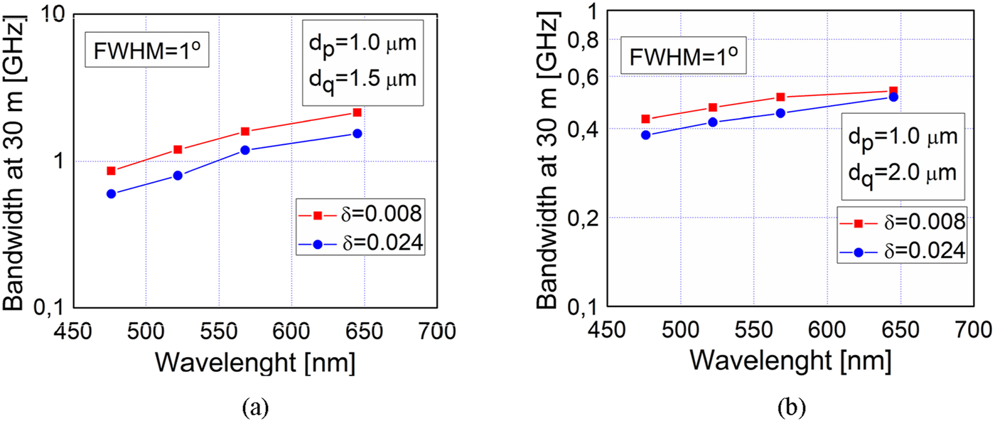
Calculated bandwidth at 30 m vs. wavelength for W-type mPOF with δ = 0.008 and 0.024, and dp = 1 μm, for Gaussian beam excitation with FWHM = 1o, (A)dq = 1.5 μm and (B)dq = 2 μm.
FIGURE 3
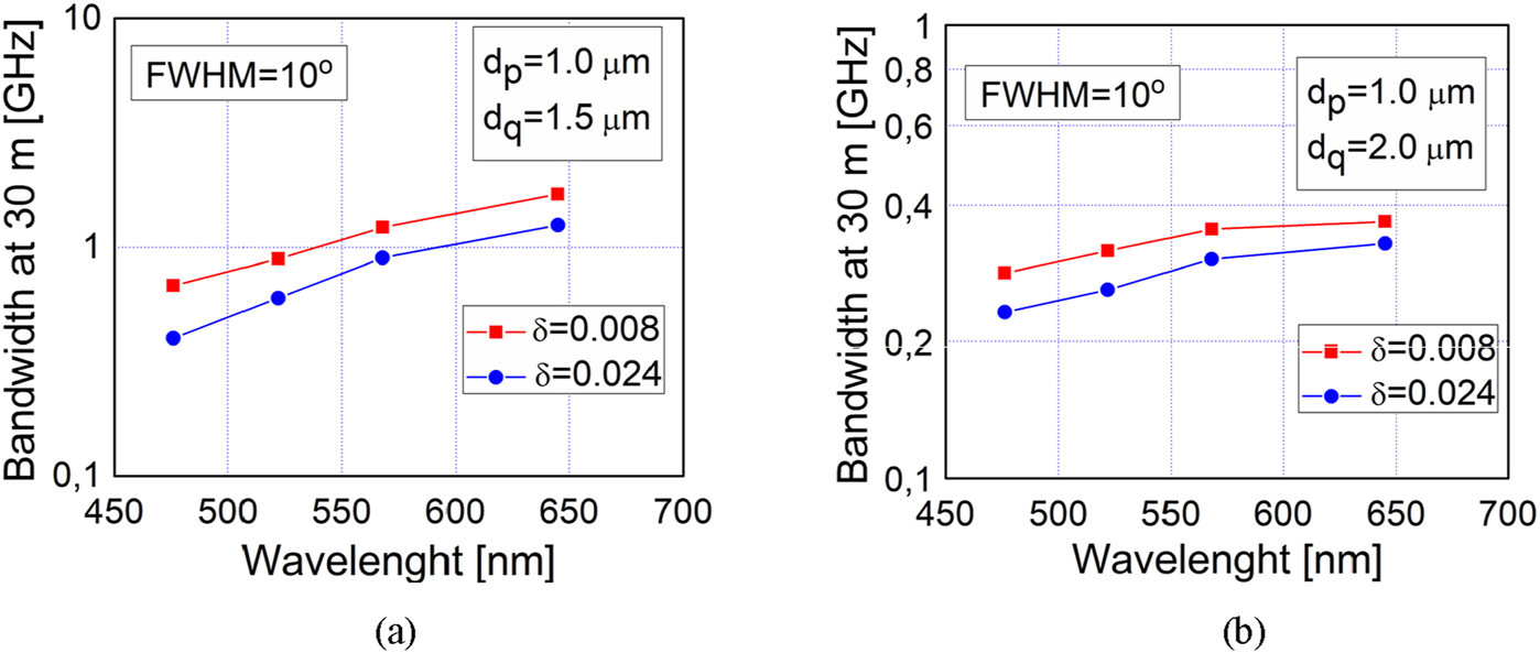
Calculated bandwidth at 30 m vs. wavelength for W-type mPOF with δ = 0.008 and 0.024, and dp = 1 μm, for Gaussian beam excitation with FWHM = 10o, (A)dq = 1.5 μm and (B)dq = 2 μm.
The results presented in this work can be useful for employment the investigated W-type mPOF for data communication in short-range communication systems, such as those within buildings. The visible spectrum is the most commonly utilized wavelength range for consumer electronics. W-type POFs can also be used for decorative and automotive lighting, especially in applications where flexibility is important (e.g., car interiors or illuminated signs). Also, the obtained results can be useful for employment of the W-type POFs as a part of various sensory systems which operate at different visible wavelengths.
5 Conclusion
Bandwidth is numerically determined across a range of visible light beam wavelengths for W-type mPOFs with varying widths of the intermediate layer and different FWHM values of the launch beam. We showed that bandwidth increases with larger wavelengths, as well as with thinner and shallower inner cladding and narrower centrally launched beams. This characterization aligns with the observed effectiveness of these fibers in minimizing modal dispersion and enhancing bandwidth. Such findings enable the customization of various W-type optical fibers for specific applications at different wavelengths. In our future work, the W-type mPOF with graded index core distribution will be investigated, which is a promising fiber design for further enhancing the bandwidth.
Statements
Data availability statement
The raw data supporting the conclusions of this article will be made available by the authors, without undue reservation.
Author contributions
BD: Conceptualization, Formal Analysis, Methodology, Software, Visualization, Writing–original draft. AS: Conceptualization, Formal Analysis, Investigation, Methodology, Software, Visualization, Writing–review and editing. AD: Conceptualization, Formal Analysis, Funding acquisition, Methodology, Validation, Writing–review and editing. KA: Conceptualization, Formal Analysis, Investigation, Methodology, Validation, Visualization, Writing–review and editing. SS: Conceptualization, Formal Analysis, Funding acquisition, Investigation, Methodology, Project administration, Supervision, Writing–original draft, Writing–review and editing.
Funding
The author(s) declare that financial support was received for the research, authorship, and/or publication of this article. The Serbian Ministry of Science, Technological Development, and Innovations (Agreement Nos 451-03-65/2024-03/200122; 451-03-65/2024-03/200123) and Ajman University (Grant ID: 2023-IRG-ENIT-14; 2024-IRG-ENIT-10) provided funding for this study.
Conflict of interest
The authors declare that the research was conducted in the absence of any commercial or financial relationships that could be construed as a potential conflict of interest.
Generative AI statement
The author(s) declare that no Generative AI was used in the creation of this manuscript.
Publisher’s note
All claims expressed in this article are solely those of the authors and do not necessarily represent those of their affiliated organizations, or those of the publisher, the editors and the reviewers. Any product that may be evaluated in this article, or claim that may be made by its manufacturer, is not guaranteed or endorsed by the publisher.
References
1.
KnightJCBirksTARussellPSJAtkinDM. All-silica single-mode optical fiber with photonic crystal cladding. Opt Lett (1996) 21:1547–9. 10.1364/ol.21.001547
2.
BirksTAKnightJCRussellPSJ. Endlessly single-mode photonic crystal fiber. Opt Lett (1997) 22:961–3. 10.1364/ol.22.000961
3.
RussellPSJ. Photonic crystal fibers. Science (2003) 299:358–62. 10.1126/science.1079280
4.
KnightJC. Photonic crystal fiber. Nature (2003) 424:847–51.
5.
RussellPSJ. Photonic-crystal fibers. J Lightwave Technol (2006) 24:4729–49. 10.1109/jlt.2006.885258
6.
KnightJCBroengJBirksTARussellPSJ. Photonic band gap guidance in optical fibers. Science (1998) 282:1476–8. 10.1126/science.282.5393.1476
7.
KnightJCRussellPSJ. Photonic crystal fibers: New way to guide light. Science (2002) 296:276–7.
8.
CreganRFManganBJKnightJCBirksTARussellPSJRobertsPJet alSingle-mode photonic band gap guidance of light in air. Science (1999) 285:1537–9. 10.1126/science.285.5433.1537
9.
Amezcua-CorreaRGeromeFLeon-SavalSGBroderickNGRBirksTAKnightJC. Control of surface modes in low loss hollow core photonic bandgap fibers. Opt Express (2008) 16:1142–9. 10.1364/oe.16.001142
10.
ZhangZHeJDuBGuoKWangY. Highly sensitive gas refractive index sensor based on hollow-core photonic bandgap fiber. Opt Express (2019) 27:29649–58. 10.1364/oe.27.029649
11.
ZhangXGaoSWangYDingWWangXWangP. 7-cell hollow-core photonic bandgap fiber with broad spectral bandwidth and low loss. Opt Express (2019) 27:11608–16. 10.1364/oe.27.011608
12.
BenabidFKnightJCAntonopoulosGRussellPSJ. Stimulated Raman scattering in hydrogen-filled hollow-core photonic crystal fiber. Science (2002) 298:399–402. 10.1126/science.1076408
13.
LightPSBenabidFCounyFMaricMLuitenAN. Electromagnetically induced transparency in Rb-filled coated hollow-core photonic crystal fiber. Opt Lett (2007) 32:1323–5. 10.1364/ol.32.001323
14.
MogilevtsevDBirksTARussellPSJ. Group-velocity dispersion in photonic crystal fibers. Opt Lett (1998) 23:1662–4. 10.1364/ol.23.001662
15.
NairAAAmiriISBoopathiCSKarthikumarSJayarajuMYupapinP. Numerical investigation of co-doped microstructured fiber with two zero dispersion wavelengths. Results Phys (2018) 10:766–71. 10.1016/j.rinp.2018.07.032
16.
HuangYYangHZhaoSMaoYChenS. Design of photonic crystal fibers with flat dispersion and three zero dispersion wavelengths for coherent supercontinuum generation in both normal and anomalous regions. Results Phys (2021) 23:104033. 10.1016/j.rinp.2021.104033
17.
AnasMTAsaduzzamanSAhmedKBhuiyanT. Investigation of highly birefringent and highly nonlinear Hexa Sectored PCF with low confinement loss. Results Phys (2018) 11:1039–43. 10.1016/j.rinp.2018.11.013
18.
RajeshAChandruSRobinsonS. Investigation of defective hybrid cladding with silicon nanocrystal PCF for supercontinuum generation. Laser Phys (2021) 31:126206. 10.1088/1555-6611/ac32da
19.
KuliesaiteMJarutisVPimpeJVengelisJ. Partially coherent UV–VIS light generation in photonic crystal fiber using femtosecond pulses. Results Phys (2021) 31:104965. 10.1016/j.rinp.2021.104965
20.
PaulBKMoctaderMGAhmedKKhalekMA. Nanoscale GaP strips based photonic crystal fiber with high nonlinearity and high numerical aperture for laser applications. Results Phys (2018) 10:374–8.
21.
WuDGuoZWuZShumP. 900 nm waveband four wave mixing generation in highly nonlinear photonic crystal fiber. J Opt (2018) 20:035501. 10.1088/2040-8986/aaa9ea
22.
YuanJKangZLiFZhouGSangXWuQet alPolarization-dependent intermodal four-wave mixing in a birefringent multimode photonic crystal fiber. Opt Lett (2017) 42:1644–7. 10.1364/ol.42.001644
23.
DasSDeMSinghVK. Single mode dispersion shifted photonic crystal fiber with liquid core for optofluidic applications. Opt Fiber Technol (2019) 53:102012. 10.1016/j.yofte.2019.102012
24.
MonfaredYELiangCKhosraviRKacerovskaBYangS. Selectively toluene-filled photonic crystal fiber Sagnac interferometer with high sensitivity for temperature sensing applications. Results Phys (2019) 13:102297. 10.1016/j.rinp.2019.102297
25.
WadsworthWPercivalRBouwmansGKnightJBirksTHedleyTet alVery high numerical aperture fibers. IEEE Photon Technol Lett (2004) 16:843–5. 10.1109/lpt.2004.823689
26.
HansenKP. High-power photonic crystal fibers. the Proc SPIE (2006) 6102:61020B–61020B–11.
27.
HansenKPOlaussonCBBroengJNoordegraafDMaackMDAlkeskjoldTTet alAirclad fiber laser technology. Opt Eng (2011) 50:111609. 10.1117/1.3631872
28.
StepienRSiwickiBPyszDStepniewskiGKujawaIKlimczakMet alCharacterization of a large core photonic crystal fiber made of lead–bismuth–gallium oxide glass for broadband infrared transmission. Opt Quant Electron (2014) 46:553–61. 10.1007/s11082-013-9835-5
29.
TefelskaMMErtmanSWolinskiTRMergoPDabrowskiR. Large area multimode photonic band-gap propagation in photonic liquid-crystal fiber. IEEE Photon Technol Lett (2012) 24:631–3. 10.1109/lpt.2012.2184278
30.
AmitonovaLVDesclouxAPetschulatJFroszMHAhmedGBabicFet alHigh-resolution wavefront shaping with a photonic crystal fiber for multimode fiber imaging. Opt Lett (2016) 41:497–500. 10.1364/ol.41.000497
31.
GlogeD. Optical power flow in multimode fibers. Bell Syst Tech J (1972) 51:1767–83. 10.1002/j.1538-7305.1972.tb02682.x
32.
RousseauMJeunhommeL. Numerical solution of the coupled-power equation in step index optical fibers. IEEE Trans Microw Theor Tech. (1977) 25:577–85. 10.1109/tmtt.1977.1129162
33.
SaitohKKoshibaM. Empirical relations for simple design of photonic crystal fibers. Opt Express (2005) 13:267–74. 10.1364/opex.13.000267
34.
SimovićADjordjevichADrljačaBSavovićSMinR. Investigation of bandwidth in multimode graded index plastic optical fibers. Opt Express (2021) 29:29587–94. 10.1364/oe.433481
35.
TanakaTPYamadaS. Steady-state characteristics of multimode W-type fibers. Appl Opt (1979) 18:3261–4. 10.1364/ao.18.003261
36.
SavovićSKovačevićMSSimovićADrljačaBKuzmanovićLDjordjevichA. Method for investigation of mode coupling in multimode step-index silica photonic crystal fibers. Optik (2021) 246:167728. 10.1016/j.ijleo.2021.167728
37.
SavovićSSimovićADrljačaBKovačevićMSKuzmanovićLDjordjevichAet alHigh bandwidth performance of multimode graded-index microstructured polymer optical fibers. Res Phys (2023) 50:106548. 10.1016/j.rinp.2023.106548
38.
SimovićASavovićSDrljačaBDjordjevichA. Influence of the fiber design and launch beam on transmission characteristics of W-type optical fibers. Opt Laser Technol (2015) 68:151–9.
39.
SavovićSKovačevićMSDrljačaBSimovićAKuzmanovićLDjordjevichA. Power flow in multimode step-index plastic photonic crystal fibers. Optik (2021) 247:167868. 10.1016/j.ijleo.2021.167868
40.
MisraSBalaISwainKSatpathyRPalaiGMisraCS. Optimization of microstructred fiber’s mode distribution for high speed data transmission. J Opt (2024). 10.1007/s12596-024-01881-3
41.
MishraCSArunachalamRNayakCNayakMRSahuSKPalaiG. Realization of attenuator and amplifier using photonic crystal fiber. Silicon (2022) 14:4509–14. 10.1007/s12633-021-01231-z
42.
DasAMondalSRPanigrahiPKPalaiG. A proposal for vacuum ultraviolet torch using plasmonic-based photonic crystal fibre. Indian J Phys (2022) 96:1813–9. 10.1007/s12648-021-02111-3
Summary
Keywords
POFs, microstructured optical fibers, bandwidth, power flow equation
Citation
Drljača B, Simović A, Djordjevich A, Aidinis K and Savović S (2025) Improving the bandwidth of microstructured multimode W-type POFs in the visible light range. Front. Phys. 13:1537525. doi: 10.3389/fphy.2025.1537525
Received
01 December 2024
Accepted
10 February 2025
Published
25 February 2025
Volume
13 - 2025
Edited by
Yaping Dan, Shanghai Jiao Tong University, China
Reviewed by
Satyendra Kumar Mishra, Centre Tecnologic De Telecomunicacions De Catalunya, Spain
G. Palai, Sri Sri University, India
Updates
Copyright
© 2025 Drljača, Simović, Djordjevich, Aidinis and Savović.
This is an open-access article distributed under the terms of the Creative Commons Attribution License (CC BY). The use, distribution or reproduction in other forums is permitted, provided the original author(s) and the copyright owner(s) are credited and that the original publication in this journal is cited, in accordance with accepted academic practice. No use, distribution or reproduction is permitted which does not comply with these terms.
*Correspondence: Svetislav Savović, savovic@kg.ac.rs
Disclaimer
All claims expressed in this article are solely those of the authors and do not necessarily represent those of their affiliated organizations, or those of the publisher, the editors and the reviewers. Any product that may be evaluated in this article or claim that may be made by its manufacturer is not guaranteed or endorsed by the publisher.