 Shengyu Hu
 Zhiwei Guo
 Lijuan Dong
 Fusheng Deng
 Haitao Jiang
 Hong Chen
- 1Key Laboratory of Advanced Micro-Structure Materials, MOE, School of Physics Science and Engineering, Tongji University, Shanghai, China
- 2Shanxi Provincial Key Laboratory of Microstructure Electromagnetic Functional Materials, Shanxi Datong University, Datong, China
Optical non-reciprocal transmission plays an important role in many applications such as optical isolation, switching, and integrated photonic circuits. However, the non-reciprocity of natural magneto-optical (MO) materials is too weak to be widely used in the actual applications. Magnetized metamaterials enable the exploration of a new regime about the MO effect, including the enhanced non-reciprocal transmission and one-way surface waves. In this work, the Fano-type interference effect is studied in the heterostructure composed of a magnetized epsilon-near-zero material and a truncated photonic crystal. The inherent weak MO activity is significantly enhanced in the heterostructure because of the field intensity enhancement mechanism and Fano interference. The results provide a way to design novel optical non-reciprocal devices with excellent performance using metamaterials.
Introduction
The non-reciprocal transmission phenomenon, which breaks the symmetry of time inversion, has attracted more and more attention recently. The magneto-optical (MO) effect provides a stable, ultrafast, and high-resolution optical control method, and the non-reciprocity revealed by the Onsager–Casimir principle has a wide range of applications (Kharratian et al., 2020), such as optical isolators (Takeda and John, 2008; Bi et al., 2011; Zhang et al., 2019), all-optical signal processing, circulators (Smigaj et al., 2010; Dmitriev et al., 2012; Pintus et al., 2013), and fast imaging (Zhang et al., 2018). Thus far, however, structures have usually exhibited a weak one-way transmission effect even under some judicious designs as the strength of MO activity of the natural materials is extremely small. Metamaterials, artificial materials composed of subwavelength unit cells, provide a powerful platform for manipulating the propagation of light (Liberal and Engheta, 2017; Niu et al., 2018; Guo et al., 2022). Leviyev et al. (2017) proposed that the one-way surface plasmon polaritons (SPPs) can be realized based on the MO hyperbolic metamaterials. In particular, the photonic crystals (PCs) containing the metamaterials have become the focus of scientific research because of their unique characteristics of enhancing light–matter interactions (Guan et al., 2006). Guo et al. (2018) uncovered the non-reciprocal transmission in the one-dimensional (1D) PCs with the magnetized epsilon-near-zero (ENZ) defect. Moreover, they showed that the wavelength difference of transmission peaks along two opposite incident directions can be significantly enhanced over two orders of magnitude compared with the bismuth iron garnet MO defect. This large non-reciprocal effect does not resort to the enhancement of MO activity by the strong external magnetic field and opens novel routes to exploit advanced materials for steering the non-reciprocal transmission of electromagnetic waves in nano-scale structures (Sounas et al., 2013; Guo et al., 2018). We know that some special interference effects will significantly enhance the interaction between light and matter. Therefore, the interference effect combined with MO metamaterials and PCs is promising to further enhance the MO effect.
Fano interference is a ubiquitous scattering wave phenomenon, and it can describe the interaction of waves from quantum interference to classical physics (Fano, 1961; Miroshnichenko et al., 2010; Limonov et al., 2017). At present, Fano interference in classical systems has produced a series of interesting physical phenomena and applications, such as slow light effect (Wu et al., 2011), molecular recognition (Yanik et al., 2011; Wu et al., 2012), optical switching (Argyropoulos et al., 2012; Dabidian et al., 2015), sensing (Gupta et al., 2017), and coding (Manjappa et al., 2018). It is worth mentioning that Zhang et al. (2013) found that Fano interference can be used to significantly reduce the threshold value of optical switching and bistability. In addition, Singh et al. (2014) found new high-sensitivity sensors based on Fano interference, and the sensitivity even exceeds quadrupole resonance. Although Fano interference can be used to enhance the light–matter interaction, it is mainly realized by adjusting structural parameters (Vlasov et al., 2001; Rybin et al., 2009; Poddubny et al., 2012; Rybin et al., 2013; Pariente et al., 2016; Rybin et al., 2016; Tribelsky and Miroshnichenko, 2016). It is very meaningful to realize the Fano interference of active control (Ott et al., 2013).
In this work, aiming at the aforementioned problems, we study the Fano interference realized by heterostructures composed of ENZ material and truncated photonic crystals. In particular, we verify that the asymmetric transmittance profile of the heterostructure spectrum due to Fano-type interference can be flexibly tuned by controlling the direction of the external magnetic field. The MO enhancement properties of isotropic and anisotropic ENZ materials are similar. Therefore, our results not only reveal an actively controlled Fano interference using the external magnetic field but also demonstrate the field enhancement effect of the ENZ material, together with the asymmetric characteristic of the Fano-type transmission, can enhance the MO effect and realize non-reciprocal transmission. In addition to non-reciprocal transmission, the results of this study also provide new ways for bound states in the continuum (BIC) (Bogdanov et al., 2019; Tan et al., 2020) and topological state (Zangeneh-Nejad and Fleury, 2019) manipulation, which is expected to be used to construct new optical sensors (Guo et al., 2021a), lasers (Yu et al., 2021), and energy transfer devices (Pham et al., 2017; Guo et al., 2021b).
Results and Discussion
We consider the structure, shown in Figure 1, which is composed of a magnetized isotropic epsilon-near-zero (ENZ) material layer M and a truncated PC: (AB)n. In particular, M, A, and B correspond to the Ag, SiO2, and TiO2, respectively. The electromagnetic waves with transverse magnetic (TM) polarization (Ex, Hy, Ez) launch into the structure with an incident angle
where
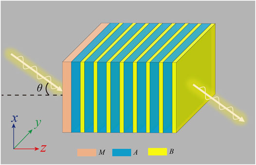
FIGURE 1. Schematic of the heterostructure composed of a magnetized isotropic ENZ layer M and a truncated PC: (AB)n. M, A, and B correspond to the Ag, SiO2, and TiO2, respectively. The incident electromagnetic waves launch into the structure from the left at an incident angle
For the magnetized Ag layer in Eq. 1, the TM and transverse electric (TE) polarization are completely decoupled, and the EMs will maintain their initial polarization during propagation. As a result, the concise 2
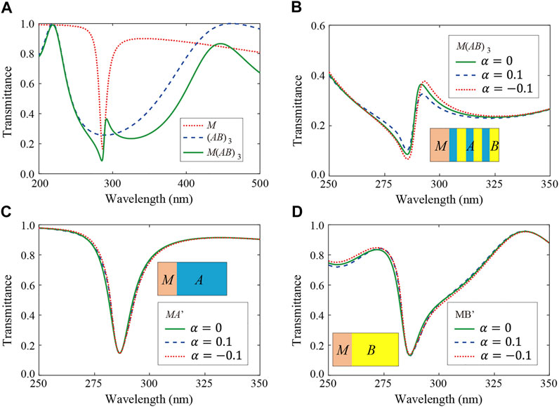
FIGURE 2. (A) Transmittance spectrum of single M layer, the 1DPC: (AB)3, and their composite structure M(AB)3 without external magnetic field
The sign of the MO coefficient
In order to realize the MO effect based on the Fano-type interference effect in the heterostructure composed of epsilon-near-zero materials and truncated photonic crystals, we further study the dependence of the transmittance spectrum of the heterostructure M(AB)3 on the incident angle, the thickness of layer M, and the strength of MO coefficient
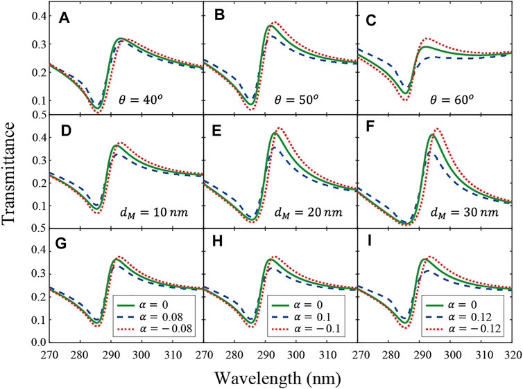
FIGURE 3. (A)–(C) Transmittance spectrum of the composite structure M(AB)3 for different incident angles: θ = 40° (A), θ = 50° (B), and θ = 60° (C). Solid green line, dashed blue line, and dotted red line denote the results for MO coefficient:

TABLE 1. Difference between the
Next, we study the dependence of MO effect on the incident angles, while the thickness of layer M and the strength of MO coefficient are fixed at dM = 10 nm and |
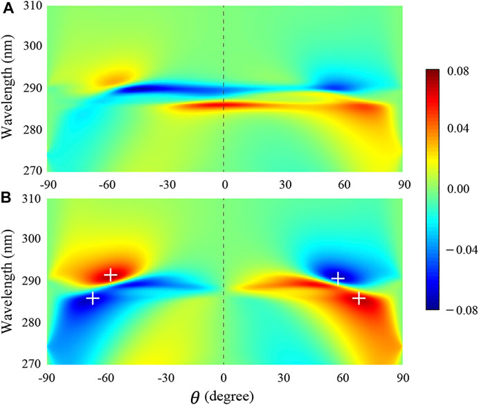
FIGURE 4. (A) Dependence of
The Fano profile of the heterostructure M(AB)3 with magnetized ENZ material can also be flexibly controlled by changing the external magnetic field. Figures 5A,B show the maximum of
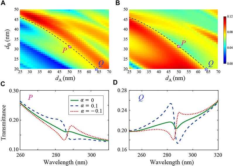
FIGURE 5. (A) Maximum of
The Fano-type interference effect in heterostructures actually exists in both isotropic and anisotropic ENZ components, regardless of the effective electromagnetic parameters. The heterostructures C(AB)n composed of an effective anisotropic magnetized ENZ layer and a truncated PC are studied. Similar to Figure 1, the schematic of the heterostructure with the effective anisotropic ENZ layer is shown in Figure 6A. Here the anisotropic ENZ layer is mimicked by subwavelength SiO2/Ag/SiO2 stacks as (DEF)M. The unit cell of SiO2/Ag/SiO2 ensures that Ag is always clamped by SiO2, and the SiO2 layer plays a role in protecting the Ag layer. The thickness of the layers D, E, and F are 5 nm, 3, and 2 nm, respectively. Because the thickness of unit cell
where
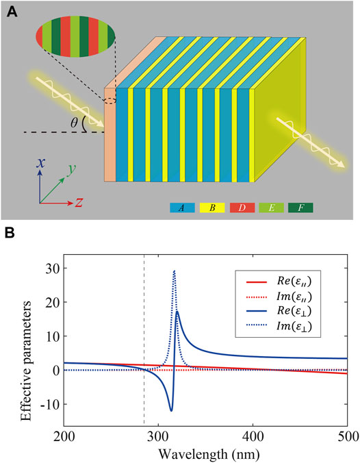
FIGURE 6. (A) Schematic of the heterostructure composed of an effective magnetized anisotropic ENZ material layer (DEF)m and a truncated PC: (AB)n. D and F correspond to the SiO2 layer with the thickness of 5 and 2 nm, respectively. E denotes the Ag layer with the thickness of 3 nm. The incident electromagnetic waves launch into the structure from the left at an incident angle
Here the enhanced MO effect by Fano interference is studied based on the narrow discrete resonance of the effective anisotropic ENZ layer and the broadband reflection of the truncated PC, as shown in Figure 7A. The incident angle is set as θ = 50°. Similar to Figure 2A, the constructive and destructive interference of the Fano-type spectrum is given based on the single C layer and the truncated PC (The transfer matrix of the effective anisotropic MO ENZ material can be found in the Supplementary Material). It can be seen that for the effective anisotropic ENZ layer, the transmittance spectrum exhibits a sharp transmission dip at 286 nm, which corresponds to a narrow discrete resonance, as shown by the dashed line in Figure 7A. Although EMT will become more effective with the increase of the number of unit cells, in the actual structure, we use limited unit cells m = 3 to illustrate the applicability of EMT. The transmittance spectrum of the (DEF)3 is marked by the red dotted line, which met well with the results of effective single C layer. In addition, the transmittance spectrum of the truncated PC (AB)3 is given by the blue dashed line, which exhibits a broadband reflection from 218 to 416 nm. As a result, the interference between the discrete and broadband reflection pathway leads to the asymmetric Fano-type spectrum for the heterostructure. The transmission peak and dip at 285.4 and 295.1 nm can be clearly identified, respectively. The transmission spectrum of C(AB)3 and (DEF)3(AB)3 nearly overlaps which further confirms the applicability of EMT. In particular, the transmittance spectrum of the composite structure C(AB)3 for different MO coefficient
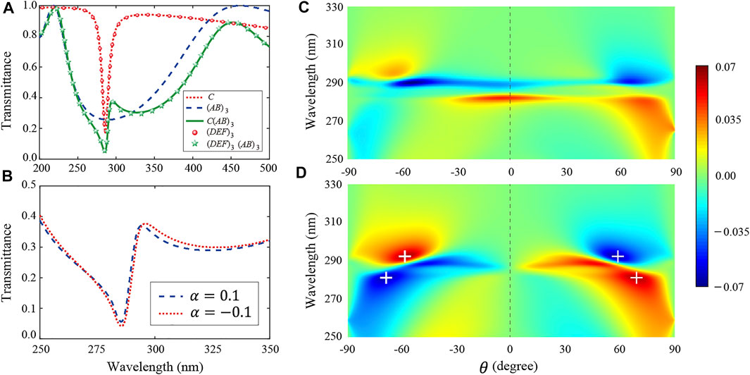
FIGURE 7. (A) Transmittance spectrum of C layer based on the effective parameters from (DEF)m, the 1DPC: (AB)3, the composite structure: C(AB)3, the multilayer structure: (DEF)3, and the composite structure: (DEF)3(AB)3, which corresponds to the dotted red line, dashed blue line, solid green line, red dotted line, and green star line, respectively. The incident angle is θ = 50°. (B) The transmittance spectrum of the composite structure (DEF)3(AB)3 for different external magnetic field:
From the maximum of
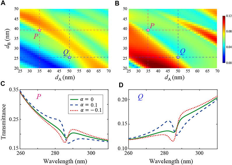
FIGURE 8. (A) Maximum of
Conclusion
In summary, we investigated the Fano-type interference effect in the heterostructure composed of a homogenous isotropic (or an effective anisotropic) magnetized ENZ material layer and a truncated dielectric photonic crystal. The ENZ material provides a narrow reflection pathway, and the photonic crystal provides a broadband reflection pathway, which gives rise to the asymmetric Fano-type spectrum. By means of the field intensity enhancement of ENZ material and the Fano interference of the heterostructure, the enhanced MO activity is demonstrated from the non-reciprocal transmission spectrum. In particular, the MO effect which depends on the incident angle, the thickness of MO layer, and the MO coefficient is studied. Moreover, the asymmetric transmittance profile of the heterostructure spectrum can be flexibly tuned by controlling the direction of the external magnetic field. These results provide a new perspective to design novel magneto-optical devices with coherence mechanisms, such as optical isolators, high-sensitivity sensors, and switches.
Data Availability Statement
The original contributions presented in the study are included in the article/Supplementary Material; further inquiries can be directed to the corresponding authors.
Author Contributions
ZG and HJ put forward the initial idea and supervised the project. ZG and SH performed the theoretical calculations and wrote the manuscript. LD, FD, HJ, and HC helped with the theoretical analyses. All the authors contributed fully to the research. ZG and SH contributed equally to this work.
Funding
This work was supported by the National Key R&D Program of China (Grant No. 2016YFA0301101), the National Natural Science Foundation of China (NSFC) (Grant Nos. 12004284, 11774261, and 61621001), the Shanghai Science and Technology Committee (Grant No. 18JC1410900), the China Postdoctoral Science Foundation (Grant Nos. 2019TQ0232 and 2019M661605), the Fundamental Research Funds for the Central Universities (Grant No. 22120210579), and the Shanghai Super Postdoctoral Incentive Program.
Conflict of Interest
The authors declare that the research was conducted in the absence of any commercial or financial relationships that could be construed as a potential conflict of interest.
Publisher’s Note
All claims expressed in this article are solely those of the authors and do not necessarily represent those of their affiliated organizations, or those of the publisher, the editors, and the reviewers. Any product that may be evaluated in this article, or claim that may be made by its manufacturer, is not guaranteed or endorsed by the publisher.
Supplementary Material
The Supplementary Material for this article can be found online at: https://www.frontiersin.org/articles/10.3389/fmats.2022.843265/full#supplementary-material
References
Argyropoulos, C., Chen, P.-Y., Monticone, F., D’Aguanno, G., and Alù, A. (2012). Nonlinear Plasmonic Cloaks to Realize Giant All-Optical Scattering Switching. Phys. Rev. Lett. 108, 263905. doi:10.1103/physrevlett.108.263905
Bi, L., Hu, J., Jiang, P., Kim, D. H., Dionne, G. F., Kimerling, L. C., et al. (2011). On-chip Optical Isolation in Monolithically Integrated Non-reciprocal Optical Resonators. Nat. Photon 5, 758–762. doi:10.1038/nphoton.2011.270
Bogdanov, A. A., Koshelev, K. L., Kapitanova, P. V., Rybin, M. V., Gladyshev, S. A., Sadrieva, Z. F., et al. (2019). Bound States in the Continuum and Fano Resonances in the strong Mode Coupling Regime. Adv. Photon. 1, 016001. doi:10.1117/1.ap.1.1.016001
Dabidian, N., Kholmanov, I., Khanikaev, A. B., Tatar, K., Trendafilov, S., Mousavi, S. H., et al. (2015). Electrical Switching of Infrared Light Using Graphene Integration with Plasmonic Fano Resonant Metasurfaces. ACS Photon. 2, 216–227. doi:10.1021/ph5003279
Dmitriev, V., Kawakatsu, M. N., and de Souza, F. J. M. (2012). Compact Three-Port Optical Two-Dimensional Photonic crystal-based Circulator of W-Format. Opt. Lett. 37, 3192. doi:10.1364/ol.37.003192
Fano, U. (1961). Effects of Configuration Interaction on Intensities and Phase Shifts. Phys. Rev. 124, 1866–1878. doi:10.1103/physrev.124.1866
Guan, G., Jiang, H., Li, H., Zhang, Y., Chen, H., and Zhu, S. (2006). Tunneling Modes of Photonic Heterostructures Consisting of Single-Negative Materials. Appl. Phys. Lett. 88, 211112. doi:10.1063/1.2207218
Guo, Z., Jiang, H., and Chen, H. (2022). Zero-index and Hyperbolic Metacavities: Fundamentals and Applications. J. Phys. D: Appl. Phys. 55, 083001. doi:10.1088/1361-6463/ac2e89
Guo, Z., Long, Y., Jiang, H., Ren, J., and Chen, H. (2021). Anomalous Unidirectional Excitation of High-K Hyperbolic Modes Using All-Electric Metasources. Adv. Photon. 3, 036001. doi:10.1117/1.ap.3.3.036001
Guo, Z., Wu, F., Xue, C., Jiang, H., Sun, Y., Li, Y., et al. (2018). Significant Enhancement of Magneto-Optical Effect in One-Dimensional Photonic Crystals with a Magnetized Epsilon-Near-Zero Defect. J. Appl. Phys. 124, 103104. doi:10.1063/1.5042096
Guo, Z., Zhang, T., Song, J., Jiang, H., and Chen, H. (2021). Sensitivity of Topological Edge States in a Non-hermitian Dimer Chain. Photon. Res. 9, 574. doi:10.1364/prj.413873
Gupta, M., Srivastava, Y. K., Manjappa, M., and Singh, R. (2017). Sensing with Toroidal Metamaterial. Appl. Phys. Lett. 110, 121108. doi:10.1063/1.4978672
Pariente, J. A., Bayat, F., Pecharomán, C., Blanco, A., García-Martín, A., and López, C., Percolation in Photonic Crystals Revealed by Fano Resonance, arXiv: 1607.08890 (2016).
Kharratian, S., Urey, H., and Onbaşlı, M. C. (2020). Advanced Materials and Device Architectures for Magnetooptical Spatial Light Modulators. Adv. Opt. Mater. 8, 1901381. doi:10.1002/adom.201901381
Leviyev, A., Stein, B., Christofi, A., Galfsky, T., Krishnamoorthy, H., Kuskovsky, I. L., et al. (2017). Nonreciprocity and One-Way Topological Transitions in Hyperbolic Metamaterials. APL Photon. 2, 076103. doi:10.1063/1.4985064
Liberal, I., and Engheta, N. (2017). Near-zero Refractive index Photonics. Nat. Photon. 149. doi:10.1038/nphoton.2017.13
Limonov, M. F., Rybin, M. V., Poddubny, A. N., and Kivshar, Y. S. (2017). Fano Resonances in Photonics. Nat. Photon 11, 543–554. doi:10.1038/nphoton.2017.142
Manjappa, M., Pitchappa, P., Singh, N., Wang, N., Zheludev, N. I., Lee, C., et al. (2018). Reconfigurable MEMS Fano Metasurfaces with Multiple-Input-Output States for Logic Operations at Terahertz Frequencies. Nat. Commun. 9, 4056. doi:10.1038/s41467-018-06360-5
Miroshnichenko, A. E., Flach, S., and Kivshar, Y. S. (2010). Fano Resonances in Nanoscale Structures. Rev. Mod. Phys. 82, 2257–2298. doi:10.1103/revmodphys.82.2257
Niu, X., Hu, X., Chu, S., and Gong, Q. (2018). Epsilon-Near-Zero Photonics: A New Platform for Integrated Devices. Adv. Opt. Mater. 6, 1701292. doi:10.1002/adom.201701292
Ott, C., Kaldun, A., Raith, P., Meyer, K., Laux, M., Evers, J., et al. (2013). Lorentz Meets Fano in Spectral Line Shapes: A Universal Phase and its Laser Control. Science 340, 716–720. doi:10.1126/science.1234407
Pham, T. S., Ranaweera, A. K., Ngo, D. V., and Lee, J.-W. (2017). Analysis and Experiments on Fano Interference Using a 2D Metamaterial Cavity for Field Localized Wireless Power Transfer. J. Phys. D: Appl. Phys. 50, 305102. doi:10.1088/1361-6463/aa7988
Pintus, P., Di Pasquale, F., and Bowers, J. E. (2013). Integrated TE and TM Optical Circulators on Ultra-low-loss Silicon Nitride Platform. Opt. Express 21, 5041. doi:10.1364/oe.21.005041
Poddubny, A. N., Rybin, M. V., Limonov, M. F., and Kivshar, Y. S. (2012). Fano Interference Governs Wave Transport in Disordered Systems. Nat. Commun. 3, 914. doi:10.1038/ncomms1924
Rybin, M. V., Khanikaev, A. B., Inoue, M., Samusev, K. B., Steel, M. J., Yushin, G., et al. (2009). Fano Resonance between Mie and Bragg Scattering in Photonic Crystals. Phys. Rev. Lett. 103, 023901. doi:10.1103/PhysRevLett.103.023901
Rybin, M. V., Mingaleev, S. F., Limonov, M. F., and Kivshar, Y. S. (2016). Purcell Effect and Lamb Shift as Interference Phenomena. Sci. Rep. 6, 20599. doi:10.1038/srep20599
Rybin, M. V., Samusev, K. B., Sinev, I. S., Semouchkin, G., Semouchkina, E., Kivshar, Y. S., et al. (2013). Mie Scattering as a cascade of Fano Resonances. Opt. Express 21, 30107. doi:10.1364/oe.21.030107
Singh, R., Cao, W., Al-Naib, I., Cong, L., Withayachumnankul, W., and Zhang, W. (2014). Ultrasensitive Terahertz Sensing with High-Q Fano Resonances in Metasurfaces. Appl. Phys. Lett. 105, 171101. doi:10.1063/1.4895595
Smigaj, W., Romero-Vivas, J., Gralak, B., Magdenko, L., Dagens, B., and Vanwolleghem, M. (2010). Magneto-optical Circulator Designed for Operation in a Uniform External Magnetic Field. Opt. Lett. 35, 568–570. doi:10.1364/OL.35.000568
Sounas, D. L., Caloz, C., and Alù, A. (2013). Giant Non-reciprocity at the Subwavelength Scale Using Angular Momentum-Biased Metamaterials. Nat. Commun. 4, 2407. doi:10.1038/ncomms3407
Takeda, H., and John, S. (2008). Compact Optical One-Way Waveguide Isolators for Photonic-Band-gap Microchips. Phys. Rev. A. 78, 023804. doi:10.1103/physreva.78.023804
Tan, T. C. W., Plum, E., and Singh, R. (2020). Lattice‐Enhanced Fano Resonances from Bound States in the Continuum Metasurfaces. Adv. Opt. Mater. 8, 1901572. doi:10.1002/adom.201901572
Tribelsky, M. I., and Miroshnichenko, A. E. (2016). Giant In-Particle Field Concentration and Fano Resonances at Light Scattering by High-Refractive index Particles. Phys. Rev. A. 93 053837. doi:10.1103/physreva.93.053837
Tuz, V. R. (2016). Polaritons Dispersion in a Composite Ferrite-Semiconductor Structure Near Gyrotropic-Nihility State. J. Magnetism Magn. Mater. 419, 559–565. doi:10.1016/j.jmmm.2016.06.070
Vlasov, Y. A., Bo, X.-Z., Sturm, J. C., and Norris, D. J. (2001). On-chip Natural Assembly of Silicon Photonic Bandgap Crystals. Nature 414, 289–293. doi:10.1038/35104529
Wu, C., Khanikaev, A. B., Adato, R., Arju, N., Yanik, A. A., Altug, H., et al. (2012). Fano-resonant Asymmetric Metamaterials for Ultrasensitive Spectroscopy and Identification of Molecular Monolayers. Nat. Mater 11, 69–75. doi:10.1038/nmat3161
Wu, C., Khanikaev, A. B., and Shvets, G. (2011). Broadband Slow Light Metamaterial Based on a Double-Continuum Fano Resonance. Phys. Rev. Lett. 106, 107403. doi:10.1103/physrevlett.106.107403
Yanik, A. A., Cetin, A. E., Huang, M., Artar, A., Mousavi, S. H., Khanikaev, A., et al. (2011). Seeing Protein Monolayers with Naked Eye through Plasmonic Fano Resonances. Proc. Natl. Acad. Sci. 108, 11784–11789. doi:10.1073/pnas.1101910108
Yu, Y., Sakanas, A., Zali, A. R., Semenova, E., Yvind, K., and Mørk, J. (2021). Ultra-coherent Fano Laser Based on a Bound State in the Continuum. Nat. Photon. 15, 758–764. doi:10.1038/s41566-021-00860-5
Yu, Z., Veronis, G., Wang, Z., and Fan, S. (2008). One-Way Electromagnetic Waveguide Formed at the Interface between a Plasmonic Metal under a Static Magnetic Field and a Photonic crystal. Phys. Rev. Lett. 100, 023902. doi:10.1103/PhysRevLett.100.023902
Zangeneh-Nejad, F., and Fleury, R. (2019). Topological Fano Resonances. Phys. Rev. Lett. 122, 014301. doi:10.1103/PhysRevLett.122.014301
Zhang, G., Zhang, Z., Xu, Y., and Wang, J. (2018). High Speed Magneto-Optical Imaging System to Investigate Motion Characteristics of Arc Plasma in Enclosed Chamber. Opt. Express 26, 23156. doi:10.1364/oe.26.023156
Zhang, Y., Du, Q., Wang, C., Fakhrul, T., Liu, S., Deng, L., et al. (2019). Monolithic Integration of Broadband Optical Isolators for Polarization-Diverse Silicon Photonics. Optica 6, 473. doi:10.1364/optica.6.000473
Keywords: photonic crystal, zero-index metamaterials, magneto-optical effect, Fano interference, high-Q mode
Citation: Hu S, Guo Z, Dong L, Deng F, Jiang H and Chen H (2022) Enhanced Magneto-Optical Effect in Heterostructures Composed of Epsilon-Near-Zero Materials and Truncated Photonic Crystals. Front. Mater. 9:843265. doi: 10.3389/fmats.2022.843265
Received: 25 December 2021; Accepted: 28 February 2022;
Published: 17 March 2022.
Edited by:
Xiao-Dong Chen, Sun Yat-sen University, ChinaCopyright © 2022 Hu, Guo, Dong, Deng, Jiang and Chen. This is an open-access article distributed under the terms of the Creative Commons Attribution License (CC BY). The use, distribution or reproduction in other forums is permitted, provided the original author(s) and the copyright owner(s) are credited and that the original publication in this journal is cited, in accordance with accepted academic practice. No use, distribution or reproduction is permitted which does not comply with these terms.
*Correspondence: Haitao Jiang, amlhbmctaGFpdGFvQHRvbmdqaS5lZHUuY24=; Zhiwei Guo, MjAxNGd1b3poaXdlaUB0b25namkuZWR1LmNu