 Dai Wang
 Jian Song Yuan
 Yunchu Li3
- 1Assessment Technique Research Center of Civil Engineering, Zhengzhou University of Technology, Zhengzhou, Henan, China
- 2College of Civil Engineering, Henan University of Engineering, Zhengzhou, Henan, China
- 3School of Civil Engineering, Zhengzhou University of Technology, Zhengzhou, Henan, China
This paper presents an experimental study on the cyclic axial compressive behavior of FRP-concrete-steel hybrid double-skin tubular columns. The square column specimens were cast with an external Fiber Reinforced Polymer jackets, inner steel tube and concrete in between. The height of the columns was 500 mm and the side dimension was 150 mm. The effects of loading scheme, void ratio and diameter-thickness ratio on axial compression behavior were investigated. A total of eight columns were tested under monotonic and cyclic axial compression. The experimental results show that the effect of loading scheme on axial stress-strain envelope curve and the peak load were not significant, and the ultimate state of the square columns subjected to cyclic axial compression was very similar to that of specimens subjected to monotonic axial compression. Besides, compared with void ratio, the diameter-thickness ratio of the inner steel tube has significant influence on the peak load of the columns when subjected to cyclic axial compression.
1 Introduction
Fiber Reinforced Polymer (FRP) has been widely used in civil engineering structures in recent year to externally reinforce the existing structures and new construction as well (Hadi, 2006; Jiang and Teng, 2007; Belzer et al., 2013; Nunes et al., 2016). Among the new types of hybrid columns, FRP-concrete-steel hybrid double-skin tubular columns (DSTCs) have gained the increasing popularity (Zeng et al., 2021; Yu et al., 2019; Zeng et al., 2020). These new hybrid columns consist of inner steel tubes, external FRP tube, and concrete filled in between.
A significant number of studies have been conducted on the structural behavior of circle DSTCs subjected to monotonic axial compression (Fam and Rizkalla, 2001; Wang et al., 2015; Feng et al., 2017; Yu et al., 2017), eccentric compression (Xiao et al., 2014; Fallah Pour et al., 2019) and bending load (Estep et al., 2016; Cardoso and Vieira, 2017; Hadi and Yuan, 2017), and the test results show that the strength and ductility of core concrete have been greatly improved with the confinement of both inner and external tubes (Girão Coelho and Mottram, 2015). For example, Sofi et al. (2020) investigated the compression behavior of DSTCs confined with FRP jackets and stiffened inner steel tube, and the experimental results shows that a superior axial stress-strain behavior for sandwiched concrete than its traditional unstiffened form. Based the experimental and Finite Element results, an analysis-oriented axial stress-strain model was proposed for the confined concrete. Moshiri et al. (2015) studied the influence of multiple cross-sectional shapes on axial load-deflection behavior and ultimate axial-load capacity of DSTCs subjected to compressive loading. Sankholkar et al. (2018) examined the confinement on concrete in double skin tubular members under axial compression loads. The extensive research studies (Shao et al., 2006; Abdelkarim et al., 2018; Revathy et al., 2020) verifies the excellent performance of circle DSTCs under monotonic loading schemes.
The seismic behavior of column members is also significant for the safety of the building structures in earthquake area; therefore, some cyclic compressive tests are of great importance for the design of the novel column members. Yu et al. (2012) have performed some tests on behavior of circular hybrid DSTCs under cyclic axial compression, and the test results show that hybrid DSTCs are very ductile under cyclic axial compression. Furthermore, Albitar et al. (2015) conducted a test about the cyclic axial compressive behaviour of DSTCs infilled with high-strength concrete, and the experimental results show that both normal and high-strength concrete DSTCs exhibited a highly ductile behavior under cyclic axial compression.
Due to the advantages of the reliable beam-column connection, the square columns (Sakino et al., 2004; Chen and Ozbakkaloglu, 2016; Fallah Pour et al., 2019) are given more attention than the circular columns in some structures. For example, Zheng and Ozbakkaloglu (2017) conducted a test about square DSTCs infilled with recycled aggregate concrete, and influences of the concrete strength, cross-sectional shape, and aggregate replacement ratio were experimentally investigated. Moreover, several studies (Zakir et al., 2021) focused on the analytical investigation to quantify the influence of stiffened steel tube on the confined concrete behavior of square shaped DSTCs. However, most research studies were conducted on the monotonic axial compressive studies of the square DSTCs, and the cyclic axial compressive behaviour of the square DSTCs is not well developed.
Based on the above-mentioned discussion, an experimental program was carried out to investigate the cyclic axial compressive performance of the square DSTCs in this study. A total of 8 specimens were tested. The parameters investigated included the loading scheme, void ratio (ratio of the outer diameter of steel tube d to the outer side length of concrete b) and diameter-thickness ratio (ratio of the outer diameter of steel tube d to the thickness of steel tube t).
2 Experimental program
2.1 Specimens
A total of 8 columns were fabricated and tested under cyclic axial compression. As shown in Figure 1, the DSTCs were designed with a square FRP jackets outside and a circle steel tube inside, and the concrete were cast in between. The height of the columns was 500 mm, and the side length was 150 mm. The FRP jackets consist of 2 layers of CFRP sheets and 2 layers of GFRP sheets in the hoop direction. The detailed parameters of specimens are given in Table 1. The name of the specimens starts with the letters “XSC” to represent all the specimens in this test. The first number in the name indicate the different steel tubes, and the second number means the different loading cycles. For example, Specimen XSC2-3 refers to the DSTC specimen reinforced with Type 2 steel tube and loaded with 3 cycles. For Specimens XSC3-1a, this specimen failed due to the operational problems, as a result, the Specimen XSC3-1b with the same configuration was tested again to obtain the accurate results.
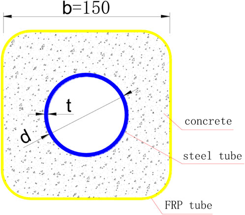
FIGURE 1. Cross-section of composite square columns.
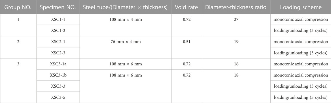
TABLE 1. Test matrix.
2.2 Materials
Both the CFRP and GFRP sheets have a thickness of 0.17 mm, and the mechanical properties of FRP sheets was tested by using GB/T 1446-2005 (GB/T1446-2005, 2005), GB/T 21490-2008 (GB/T 21490-2008, 2008) and GB/T 3354-2014 (GB/T 3354-2014, 2014). The test results in Table 2 show that the ultimate tensile strength of the CFRP sheet was 3,434 MPa and the elastic modulus was 240 GPa, and the GFRP sheets were 2,650 MPa and 160 GPa. The compressive strength of concrete cube was determined by using GB/T 50081-2019 (GB/T50081-2019, 2019), and the compressive strength is 50.8 MPa. The compressive strength of concrete prism was determined by using GB/T 50081-2019 (GB/T50081-2019, 2019), and the compressive strength is 39 MPa.
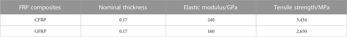
TABLE 2. FRP tension test results.
The tensile properties of the steel tube were tested by using GB/T228.1-2010 (GB/T228.1-2010, 2010). The coupons were cut from the steel tubes as shown in Figure 2, and three coupons were tested to determine the average tensile strength and average tensile modulus. The test results are given in Table 3. Moreover, three steel tubes with different specifications were subjected to axial compression, as shown in Figure 3. The loading was controlled by using force-controlled method, and the loading rate was 1 kN/s and 0.5 kN/s before and after the steel tube yielded separately. The stress-strain curves obtained are shown in Figure 4.
FIGURE 2. Tensile test of steel plate.
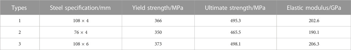
TABLE 3. Steel tension test results.
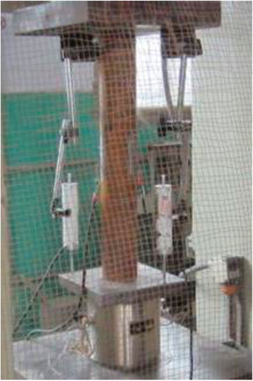
FIGURE 3. Axial compression test of steel tube.
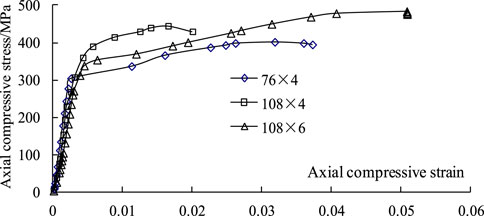
FIGURE 4. Axial stress-strain curves of steel tubes.
2.3 Preparation of specimen
The preparation of specimens mainly included two steps: casting concrete and making FRP jackets. Before casting concrete, the steel tubes installed with strain gages (Figure 5) were first carefully fixed into the formwork. The Polyvinyl chloride (PVC) tubes were divided into four small pieces, and then fixed on the four inner corners of the formwork to form the fillet. The strain gages were connected with enough long wires. After the concrete was cast and cured, the wet-layup process was employed to form the FRP jackets, as shown in Figure 6. The length of the overlap zone was 150 mm. In addition, an FRP wrap with a width of 30 mm was used at two ends of the columns to avoid the premature failure during the test.
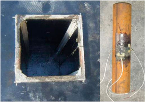
FIGURE 5. Formwork and steel tube.
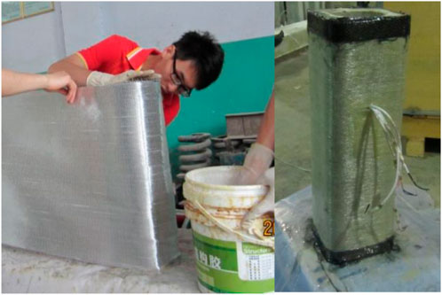
FIGURE 6. FRP jackets.
2.4 Test set-up and instrumentation
On the two longitudinal ends of steel tubes, two axial strain gauges and two hoop strain gauges were attached separately to test the strain of the steel tubes. The axial deformation of composite square columns was measured through the two opposite displacement meters installed inside at a height of 270 mm. The hoop strain was tested through 4 strain gauges evenly distributed on the lap area of the lengthways section of FRP jackets along the fiber direction, as shown in Figure 7.

FIGURE 7. Layout of strain gages.
The loading equipment is the YA-3000 electro-hydraulic pressure testing machine. The preload is 10% of the ultimate load of specimens. Force control and step loading scheme were adopted in the formal loading. The load value of each step was 10% of the ultimate load of specimens, and the load of each step were kept for 2 min. When the load reached to 90% of the ultimate load, the continuous slow loading was adopted till the end of test. All test results, including load, strain and displacement, were synchronously recorded by using IMP data collection system, as shown in Figure 8.
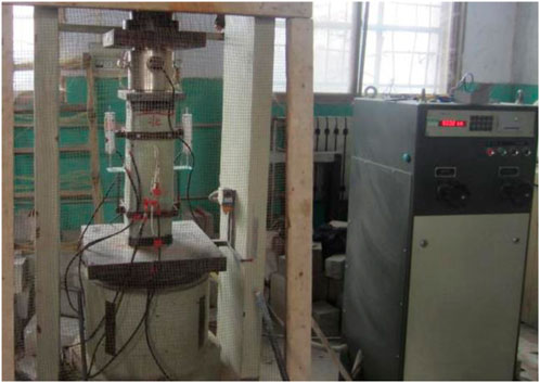
FIGURE 8. Test set-up.
The cyclic loading method adopted is completely unloading/reloading. The specimens were unloaded to 0 (in order to guarantee the stable working of the testing machine, unloading process was stop at 20 kN in this study), and then, the specimens were loaded to the unloading displacement value in the same cycle. The default unloading displacement value is set according to monotonic axial compression result of FRP-concrete-steel composite columns, to make sure that the strain of concrete at the first unloading is between 0.001 and 0.0035, and the clarification of other unloading value facilitates the unloading/loading response of constrained concrete under different degrees of plastic deformation.
3 Experimental results and discussions
3.1 Failure modes
Before the ultimate load was reached, the surface of the DSTC columns was intact without apparent damage. The columns experienced a large axial deformation and failed due to the rupture of the FRP composites with a loud noisy. The fracture of FRP jackets occurred in the middle height of the square columns, as shown in Figure 9. The strain-stress curves of all FRP-concrete-steel composite square column specimens are presented in Figure 10. The axial strain was calculated with the readings of the two displacement meters on the opposite sides of the square columns.
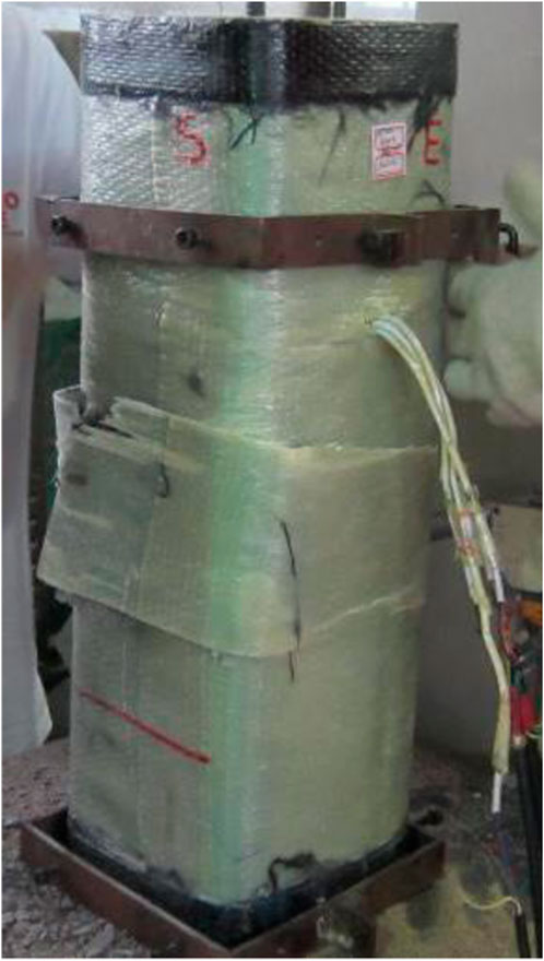
FIGURE 9. Failure mode of Specimen XSC1-3.
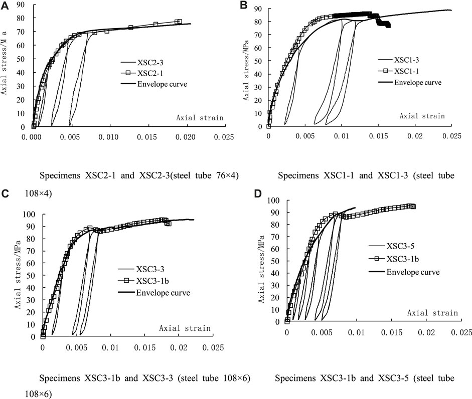
FIGURE 10. Axial stress-strain curves of composite square columns (A) Specimens XSC2-1 and XSC2-3 (steel tube 76 × 4) (B) Specimens XSC1-1 and XSC1-3 (steel tube 108 × 4) (C) Specimens XSC3-1b and XSC3-3 (steel tube 108 × 6) (D) Specimens XSC3-1b and XSC3-5 (steel tube 108 × 6).
Figure 10 shows that the DSTCs possessed good ductility under cyclic axial compression. In addition, the strain-stress envelope curves of specimens under cyclic axial compression agreed well with that under monotonic axial compression, thus suggesting that loading/unloading scheme does not influence the envelope curves. The difference between the envelope curve of XSC3-5 and XSC3-1b was comparatively obvious. One reason is that during the casting of XSC3-5, there are partial void areas in the interface between FRP jackets and concrete, leading to the weak confinement of FRP jackets. The other reason may be related the location of the unloading point. The impact of cyclic loading on cumulative plastic deformation can also be observed in Figure 10, that is, more cycles caused the greater plastic deformation.
3.2 Peak load
Table 4 and test results show that the ultimate state of specimens under cyclic axial compression is similar to that of the specimens under monotonic axial compression. Meanwhile, the peak load of cyclic axial compression and monotonic axial compression were close, with the greatest difference of 3.1%. This result implied that the cyclic axial compression did not have a significant impact on the peak load of the hollow-core FRP-concrete-steel square columns. As shown in Table 4, the peak load of XSC3-1a was obviously smaller than that of XSC3-1b, which was attributed to uneven thickness of concrete along the longitudinal direction of columns caused in casting concrete. Moreover, the effect of axial loading and unloading on the strain-stress of square column specimens was limited, and only the strain slightly increased. Also, as shown in Table 1, the void rate of the specimens in Group 2 and 3 differed, but the diameter-thickness ratio was very close. However, the peak load of the specimens in the two groups approached, with the average difference of 0.4%, suggesting that void rate did not have a significant impact on the peak load of the square columns under cyclic axial compression. The void rate of Group 1 and 3 was same. However, the diameter-thickness ratio and the peak load of the specimens in two group are different, meaning that diameter-thickness ratio has more significant influence on the peak load of composite square columns.

TABLE 4. Test results.
3.3 Effect of inner steel tube
To illustrate the influence of inner steel tube diameter (d), Table 4 presents the results of the specimens from three different groups. Each group shown in Table 4 consisted of two or three DSTCs with identical inner steel tube sizes. It can be seen from the table that an increase of diameter d caused an increase in the ultimate axial strains (
3.4 Plastic strain
Plastic strain referred to the residual strain when the stress was 0. When the strain of the steel tubes and concrete in the composite columns reached a certain value that is greater than the yield strain of steel tube, the plastic strain caused by concrete is much smaller than that caused by steel tube. That is because the non-linearity of concrete is one of the major factors for material failure and stiffness degradation. However, the plastic strain of steel tube almost completely depended on its plasticity. Therefore, in the whole unloading process, the axial compression strain of the steel tube reached 0 before the composite columns. When the axial compression was completely unloaded, steel tubes provided tensile stress to balance the compressive stress of concrete. At that moment, the slippage between the two materials occurred, and compared with the concrete, the length of the steel tube shortened more. In such a case, when the composite columns are reloaded again, the concrete immediately bear the load and the deformation. When the steel tube touched the bearing plate, the two materials generate the same axial strain again.
Figure 11 presents the axial strain of the steel tube and concrete in Specimen XSC1-3. The strain of steel tube was recorded by the axial strain gauges, and concrete by the axial displacement meters. The test results verify the above-mentioned results, especially in the final cycle (as shown in Figure 10B, the first unloading point of XSC1-3 locating in the elastic stage). Also, it is further proved that, when the load decrease to 0, the axial strain of the composite columns was normally greater than the plastic strain of concrete, and always smaller than the plastic strain of the steel tube.
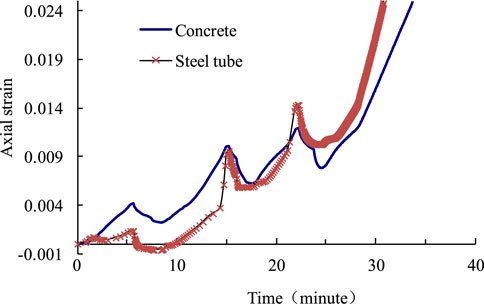
FIGURE 11. Axial strain of concrete and steel tube.
4 Conclusion
In this research study, the cyclic axial compressive behaviour of the double-skin tubular square columns has been experimentally investigated. The main parameters included the loading scheme, void ratio and diameter-thickness ratio were studied. The experimental results and the parametric analyses on the cyclic behaviour of the columns have been given. The following conclusions can be drawn.
(1) The results show that cyclic axial compression barely has any influence on the peak load of hollow-core FRP-concrete-steel square columns, and the ductility of composite square columns remains intact. Besides, repeated unloading/reloading cycles have a certain effect on the cumulative plastic deformation of composite square columns, that is, with the growth of cycles, the value of plastic deformation increases.
(2) Similar to the findings under monotonic axial compression, the diameter-thickness ratio of inner steel tube has a significant impact on the peak load of composite square columns, the higher the diameter-thickness ratio, the lower the peak load. Void rate, however, did not significantly influence the peak load of composite square columns under cyclic axial compression.
(3) Due to the difference in the plastic properties of steel tube and concrete, though the plastic strain of them is almost synchronous in the first loading/unloading cycle, with the increase of cycles and especially in the last cycle, the plastic strain of steel tube is greatly higher than that of concrete.
(4) The strain-stress envelope curves of composite square columns under cyclic axial compression agree with that of specimens under monotonic axial compression. Therefore, with the reference of the existing stress-strain models of concrete in composite columns under monotonic axial compression, the stress-strain envelope curves of concrete in composite square columns under cyclic axial compression may be accurately predicted, by considering the factor of shape of cross-section.
Data availability statement
The original contributions presented in the study are included in the article/Supplementary Material, further inquiries can be directed to the corresponding author.
Author contributions
DW: Project Administration, Supervision, Conceptualization, Investigation, Writing—Original Draft. JY: Formal analysis, Writing—Review and Editing. YL: Methodology. QF: Investigation. HZ: Investigation. All authors contributed to the article and approved the submitted version.
Funding
The authors highly appreciate the financial support from Cultivating Plan (2017GGJS183) on Young Backbones Teachers of Colleges and Universities, Henan province and National Nature Science cultivation fund program (GJJKT 2018K2), Zhengzhou University of Technology and Key Scientific and Technological Project of Henan Province (Project No. 222102520040).
Conflict of interest
The authors declare that the research was conducted in the absence of any commercial or financial relationships that could be construed as a potential conflict of interest.
Publisher’s note
All claims expressed in this article are solely those of the authors and do not necessarily represent those of their affiliated organizations, or those of the publisher, the editors and the reviewers. Any product that may be evaluated in this article, or claim that may be made by its manufacturer, is not guaranteed or endorsed by the publisher.
References
Abdelkarim, O. I., Elgawady, M. A., Anumolu, S., Gheni, A., and Sanders, G. E. (2018). Behavior of hollow-core FRP-concrete-steel columns under static cyclic flexural loading. J. Struct. Eng. 144 (2), 04017188–4017216. doi:10.1061/(asce)st.1943-541x.0001905
Albitar, M., Ozbakkaloglu, T., and Louk Fanggi, B. A. (2015). Behavior of FRP-HSC-steel double-skin tubular columns under cyclic axial compression. J. Compos. Constr. 19 (2), 4014041. doi:10.1061/(asce)cc.1943-5614.0000510
Belzer, B., Robinson, M., and Fick, D. (2013). Composite action of concrete-filled rectangular GFRP tubes. J. Compos. Constr. 17 (5), 722–731. doi:10.1061/(asce)cc.1943-5614.0000370
Cardoso, D. C. T., and Vieira, J. D. (2017). Comprehensive local buckling equations for FRP I-sections in pure bending or compression. Compos. Struct. 182, 301–310. doi:10.1016/j.compstruct.2017.09.027
Chen, L., and Ozbakkaloglu, T. (2016). Corner strengthening of square and rectangular concrete-filled frp tubes. Eng. Struct. 117, 486–495. doi:10.1016/j.engstruct.2016.03.031
Estep, D. D., GangaRao, H. V. S., Dittenber, D. B., and Qureshi, M. A. (2016). Response of pultruded glass composite box beams under bending and shear. Compos. Part B Eng. 88, 150–161. doi:10.1016/j.compositesb.2015.11.008
Fallah Pour, A., Gholampour, A., Zheng, J., and Ozbakkaloglu, T. (2019). Behavior of frp-confined high-strength concrete under eccentric compression: tests on concrete-filled frp tube columns. Compos. Struct. 220, 261–272. doi:10.1016/j.compstruct.2019.03.031
Fam, A. Z., and Rizkalla, S. H. (2001). Behavior of axially loaded concrete-filled circular fiber-reinforced polymer tubes. ACI Struct. J. 98 (3), 280–289.
Feng, P., Hu, L., Qian, P., and Ye, L. (2017). Buckling behavior of CFRP-aluminum alloy hybrid tubes in axial compression. Eng. Struct. 132, 624–636. doi:10.1016/j.engstruct.2016.11.051
Gb/T 21490-2008, (2008). Carbon fiber sheet for strengthening and restoring structures. https://webstore.ansi.org/standards/spc/gb214902008.
Gb/T 3354-2014, (2014). Test method for tensile properties of orientation fiber reinforced polymer matrix composite materials. https://www.chinesestandard.net/PDF/English.aspx/GBT3354-2014.
Gb/T1446-2005, (2005). Fiber-reinforced plastics composites-The generals for determination of properties. https://webstore.ansi.org/standards/spc/gb14462005.
Gb/T228.1-2010, (2010). Metallic materials-tensile testing-part 1: method of test at room temperature. https://www.chinesestandard.net/PDF.aspx/GBT228.1-2010.
Gb/T50081-2019, (2019). Standard for test methods of concrete physical and mechanical properties. https://www.chinesestandard.net/PDF.aspx/GBT50081-2019.
Girão Coelho, A. M., and Mottram, J. T. (2015). A review of the behaviour and analysis of bolted connections and joints in pultruded fibre reinforced polymers. Mater. Des. 74, 86–107. doi:10.1016/j.matdes.2015.02.011
Hadi, M. N. S. (2006). Comparative study of eccentrically loaded frp wrapped columns. Compos. Struct. 74 (2), 127–135. doi:10.1016/j.compstruct.2005.03.013
Hadi, M. N. S., and Yuan, J. S. (2017). Experimental investigation of composite beams reinforced with GFRP I-beam and steel bars. Constr. Build. Mater. 144, 462–474. doi:10.1016/j.conbuildmat.2017.03.217
Jiang, T., and Teng, J. G. (2007). Analysis-oriented stress–strain models for FRP–confined concrete. Eng. Struct. 29 (11), 2968–2986. doi:10.1016/j.engstruct.2007.01.010
Moshiri, N., Hosseini, A., and Mostofinejad, D. (2015). Strengthening of rc columns by longitudinal cfrp sheets: effect of strengthening technique. Constr. Build. Mater. 79, 318–325. doi:10.1016/j.conbuildmat.2015.01.040
Nunes, F., Correia, J. R., and Silvestre, N. (2016). Structural behavior of hybrid frp pultruded beams: experimental, numerical and analytical studies. Thin-Walled Struct. 106, 201–217. doi:10.1016/j.tws.2016.05.004
Revathy, J., Gajalakshmi, P., and Pavithra, P. (2020). Experimental investigation on concrete filled glass fibre reinforced polymer tubular beams under flexural loading. Mater. today Proc. 33, 440–445. doi:10.1016/j.matpr.2020.04.869
Sakino, K., Nakahara, H., Morino, S., and Nishiyama, I. (2004). Behavior of centrally loaded concrete-filled steel-tube short columns. J. Struct. Eng. 130 (2), 180–188. doi:10.1061/(asce)0733-9445(2004)130:2(180)
Sankholkar, P. P., Pantelides, C. P., and Hales, T. A. (2018). Confinement model for concrete columns reinforced with GFRP spirals. J. Compos. Constr. 22 (3), 04018007. doi:10.1061/(asce)cc.1943-5614.0000843
Shao, Y., Zhu, Z., and Mirmiran, A. (2006). Cyclic modeling of FRP-confined concrete with improved ductility. Cem. Concr. Compos. 28 (10), 959–968. doi:10.1016/j.cemconcomp.2006.07.009
Sofi, F. A., Zakir, M., and Naqash, J. A. Experimentally verified behavior of multiple-shape hybrid FRP-concrete-steel double skin tubular columns under axial compression. 1st Online International Conference on Recent Advances in Computational and Experimental Mechanics (ICRACEM 2020), Singapore, 2020.
Wang, W., Sheikh, M. N., and Hadi, M. N. S. (2015). Axial compressive behaviour of concrete confined with polymer grid. Mater. Structures/Materiaux Constr. 49, 3893–3908. doi:10.1617/s11527-015-0761-9
Xiao, J., Tresserras, J., and Tam, V. W. Y. (2014). GFRP-tube confined RAC under axial and eccentric loading with and without expansive agent. Constr. Build. Mater. 73, 575–585. doi:10.1016/j.conbuildmat.2014.09.038
Yu, T., Zhang, S., Huang, L., and Chan, C. (2017). Compressive behavior of hybrid double-skin tubular columns with a large rupture strain FRP tube. Compos. Struct. 171, 10–18. doi:10.1016/j.compstruct.2017.03.013
Yu, T., Zhao, H., Ren, T., and Remennikov, A. (2019). Novel hybrid frp tubular columns with large deformation capacity: concept and behaviour. Compos. Struct. 212, 500–512. doi:10.1016/j.compstruct.2019.01.055
Yu, T., Zhang, B., Cao, Y. B., and Teng, J. G. (2012). Behavior of hybrid frp-concrete-steel double-skin tubular columns subjected to cyclic axial compression. Thin-Walled Struct. 61 (6), 196–203. doi:10.1016/j.tws.2012.06.003
Zakir, M., Sofi, F. A., and Naqash, J. A. (2021). Compressive testing and finite element analysis-based confined concrete model for stiffened square FRP-concrete-steel double-skin tubular columns. J. Build. Eng. 44, 103267. doi:10.1016/j.jobe.2021.103267
Zeng, J-J., Gao, W-Y., Duan, Z-J., Bai, Y-L., Guo, Y-C., and Ouyang, L-J. (2020). Axial compressive behavior of polyethylene terephthalate/carbon FRP-confined seawater sea-sand concrete in circular columns. Constr. Build. Mater. 234, 117383. doi:10.1016/j.conbuildmat.2019.117383
Zeng, J-J., Zheng, Y-Z., and Long, Y-L. (2021). Axial compressive behavior of FRP-concrete-steel double skin tubular columns with a rib-stiffened Q690 steel tube and ultra-high strength concrete. Compos. Struct. 268, 113912. doi:10.1016/j.compstruct.2021.113912
Keywords: FRP, cyclic load, axial compression test, composite columns, square columns
Citation: Wang D, Yuan JS, Li Y, Fu Q and Zhang H (2023) Cyclic axial compressive performance of hybrid double-skin tubular square columns. Front. Mater. 10:1214147. doi: 10.3389/fmats.2023.1214147
Received: 29 April 2023; Accepted: 06 September 2023;
Published: 19 September 2023.
Edited by:
Behzad Nematollahi, The University of Sheffield, United KingdomReviewed by:
Jun-Jie Zeng, Guangdong University of Technology, ChinaRijalul Fikri, International Islamic University Malaysia, Malaysia
Copyright © 2023 Wang, Yuan, Li, Fu and Zhang. This is an open-access article distributed under the terms of the Creative Commons Attribution License (CC BY). The use, distribution or reproduction in other forums is permitted, provided the original author(s) and the copyright owner(s) are credited and that the original publication in this journal is cited, in accordance with accepted academic practice. No use, distribution or reproduction is permitted which does not comply with these terms.
*Correspondence: Jian Song Yuan, eXVhbmppYW5zb25nQGhvdG1haWwuY29t