 Xuexu An
 Juan Huang2
- 1School of Railway Engineering, Shaanxi College of Communications Technology, Xi’an, China
- 2School of Highway Engineering, Shaanxi College of Communications Technology, Xi’an, China
- 3School of Intelligent Science and Engineering, Xi’an Peihua University, Xi’an, China
Introduction: Deep underground excavation induces significant unloading damage in diorite, yet micromechanical mechanisms under varying unloading rates remain poorly understood.
Methods: Herein, we employed the discrete element method to investigate the microscopic and macroscopic response mechanisms of deep hard diorite samples during the loading and unloading process. We performed numerical analysis at three unloading-confining-pressure rates using PFC3D. The macroscopic mechanical characteristics, particle displacement, number of contact force chain failures, and propagation and evolution characteristics of the spatial distribution of tensile shear microcracks along the axial and radial directions of the samples during the loading and unloading process were studied.
Results: (1) Peak strength and strain increased with reduced unloading rates, while confining pressure exhibited instantaneous fluctuations during unloading, signaling progressive fracture evolution. (2) Radial particle displacement and contact force chain failures showed nonlinear concave growth from core to surface, intensifying post-peak—indicating severe near-surface damage. (3) Microcracks propagated inward from the unloading surface, with tensile cracks predominating over shear cracks. Tensile crack density increased as unloading rate decreased.
Discussion: Lower unloading rates facilitate prolonged stress redistribution, amplifying force chain failures and microcrack density. This confirms that unloading-induced damage initiates near boundaries and propagates inward, with tensile mechanisms governing failure.
1 Introduction
In underground engineering, different excavation rates cause considerable differences in the unloading mechanical characteristics of rocks (Lin et al., 2022). In recent years, with the increasing number of deep underground engineering projects in China, the unloading mechanical properties of rocks induced by excavation have attracted garnered widespread attention. Research has shown that rock failure during the unloading of high-confining-pressure conditions is often sudden and more intense than is rock failure under loading conditions. Thus, studying the macroscopic and microscopic mechanical properties of rocks under unloading rates is of considerable importance for understanding the damage and fracture evolution mechanism of rocks that are induced by deep underground engineering excavation (Zhang et al., 2023a; Zhao et al., 2021).
Many studies have investigated the unloading strength, deformation, and energy evolution characteristics of rocks through laboratory experiments (Wang et al., 202a; Zhu et al., 2021; Han et al., 2021). Lau and Chandler (2004) reported that obtaining rock mechanics parameters through unloading experiments is more in line with actual underground engineering. Chen et al. (2020b) conducted unloading tests on sandstone under different confining pressures and reported that the crack volume strain decreases with increasing confining pressure and that rock bursts are prone to occur under high unloading rates. Bing et al. (2018) conducted unloading experiments on granite and found that the unloading failure strain is smaller than the loading failure strain; furthermore, the difference between the two increases with increasing confining pressure. You et al. (2023) conducted triaxial loading and unloading experiments to determine the energy conversion law of rock samples; they found that before the loading and unloading peak strength is reached, the strain energy conversion rate increases with the increasing confining pressure. An et al. (2023) conducted triaxial loading and unloading experiments to investigate the strain energy storage and transfer mechanisms of diorite before its peak strength was reached; they found that the ultimate strain energy accumulation ability of rock samples decreases with the increasing unloading confining pressure rate. These studies have elucidated the unloading macroscopic mechanical properties of rocks.
Considering the unloading mechanical properties of rocks only from the perspectives of its strength, deformation, and energy evolution cannot provide enough insights into rock failure mechanisms. To study microcrack propagation and evolution characteristics and failure modes of rocks under unloading conditions, new technologies, such as computed tomography (CT) scanning (Wu et al., 2022; Zhao et al., 2022), acoustic emission (AE) (Li et al., 2023; Yang et al., 2023), and digital image correlation (DIC) (Tang et al., 2020), are widely employed. Wang et al. (2020b) employed the CT scanning technology to investigate the three-dimensional (3D) failure characteristics of coarse-grain marble under different unloading conditions; they showed that the 3D failure morphology of the marble is closely related to the unloading rate and time effects. An et al. (2022) and Wang et al. (2020c) employed AE to analyze damage evolution in rock samples under unloading conditions; they found that the failure of rocks during unloading is caused by microcrack initiation, propagation, and coalescence of microcracks. Chen et al. (2022) used DIC and AE techniques to demonstrate that the internal failure before the peak strength of rocks is primarily attributed to tensile cracks during loading and unloading cycles. Although these technologies are currently considerably advanced, some limitations still exist in exploring crack propagation and evolution in rocks. For example, AE cannot accurately capture the spatial position of microcracks in rocks because of signal interference; in addition, CT scanning technology cannot be used for real-time monitoring of microcrack propagation and evolution.
Numerical analysis techniques can effectively overcome the aforementioned technical shortcomings. Among various numerical methods, including the use of FLAC, particle flow code (PFC), and UDEC, etc (Liu et al., 2024; Chen et al., 2020a). The use of PFC has become important for exploring microscopic damage and fracture characteristics in rock samples (Shen et al., 2023; Zhang and Wong, 2012). Numerous studies have shown that the PFC can effectively simulate microcrack evolution in rock (Yang et al., 2019; De Silva et al., 2018; Yang and Zhang, 2020). Based on numerical analyses using PFC, Jin et al. (2019), Rong et al. (2022), Cong et al. (2019), and Li et al. (2019) found that the higher the unloading rate, the slower the propagation and evolution of microcracks in rocks but the more the internal tensile microcracks. Xiong et al. (2019) also studied the unloading mechanical properties of layered rocks using PFC2D and found that fracture evolution in layered rocks is considerably influenced by material properties and layered distribution. Ao et al. (2024) investigated the rock burst proneness of coarse-grained granite, red sandstone, and white marble under triaxial loading and unloading conditions using PFC3D. They found that coarse-grained granite exhibited the higher rock burst proneness. In addition, Zhang et al. (2023b) conducted a true triaxial unilateral unloading test on granite samples containing prefabricated cracks using PFC3D, and they found that the degradation effect of prefabricated cracks on the model strength linearly increased with decreasing inclination angle. Li et al. (2024) investigated the mechanical behavior and fracture mechanism of marble under true triaxial cyclic loading and unloading using the discrete element method. Their results indicated that as the intermediate principal stress increases or the minimum principal stress decreases, the failure surface changes from inclined to parallel to the direction of the maximum principal stress.
The aforementioned experimental and numerical studies have enhanced the understanding of the unloading macroscopic and microscopic mechanics of rock samples; however, to obtain a more comprehensive understanding of the damage response characteristics of rocks during unloading, it is necessary to further study the macroscopic and microscopic mechanical response mechanisms of rocks under loading and unloading conditions. Herein, we first constructed a diorite loading unloading numerical model using PFC3D. We then divided the numerical model into five regions in the axial and radial directions and exported basic particle information for the regions during the loading and unloading processes through programming. Finally, we applied statistical theory to study the evolution characteristics of internal particle displacement components, the number of contact force chain failures, and the tensile shear microcracks along the axial and radial directions of the involved samples. Overall, this study provides a basis for understanding the loading and unloading damage and fracture mechanism of rock samples.
2 Numerical test
2.1 Selection of contact models
PFC3D is an important tool for studying the macroscopic and microscopic mechanical properties of rocks. Numerical models developed using this software comprise numerous rigid particles bonded to the bonded materials. Some contact models are provided in PFC3D. Among them, the parallel-bond model (PBM) is often used as the basic contact model for simulating geotechnical materials. However, owing to the insufficient self-locking effect provided by the rigid particles assigned to the PBM, this model has some shortcomings, such as low unconfined compression ratio and internal friction angle and linear strength envelope when simulating brittle rocks (Yang et al., 2019). Compared with the PBM, the flat-joint model (FJM), owing to its unique structure and discretized structural element form of the particle contact surface (Figure 1a), enables particles to exhibit strong self-locking effects and rotational impedance. This model overcomes the shortcomings of the PBM and is suitable for simulating the macroscopic and microscopic mechanical behavior of rocks (Wu and Xu, 2016).
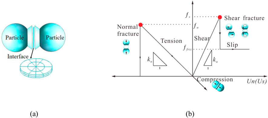
Figure 1. (a) Contact element between particles; (b) Schematic of the flat joint model (FJM).
The FJM is a cohesive contact model that considers local damages, and the elements at each particle interface assigned to the FJM have only two states: bonded and unbound (He et al., 2018). For the bonded elements, when the normal contact force of the particles is greater than the ultimate tensile stress of the bonding material, the bonding material fractures and forms tensile cracks. When the tangential contact force of the particles meets the Mohr–Coulomb strength criterion, the bonding material fractures and forms shear cracks. For the unbound elements, there is only compressive stress in the normal direction of the particles. When the tangential stress of the particles is greater than the ultimate friction force, the particles slide (Figure 1b). For more information on the FJM, refer to the PFC3D manual.
2.2 Microparameter calibration
The diorite samples analyzed herein originate from a deeply buried hard rock tunnel in the north of Qinling Mountains, Shaanxi Province, China. The total length of the tunnel is 98.3 km, and the diorite surrounding rock in the Lingbei TBM section is located in a geological environment with a high burial depth and high ground stress. During excavation, disasters such as rock burst, large deformations, rock mass peeling, and block falling occur. Therefore, it is necessary to study the macroscopic and microscopic mechanical properties of deep diorite during unloading.
The basic mechanical parameters of diorite samples were obtained using a SAS-2000 microcomputer-controlled rock triaxial test system and an RMT-150C rock mechanics testing system. The density, compressive strength, tensile strength, elastic modulus, and Poisson’s ratio of the samples are 2,680 kg/m3, 166.0 MPa, 7.56 MPa, 33.245 GPa, and 0.18, respectively. For numerical analysis, we employed a standard cylindrical sample (Φ50 mm × H100 mm) comprising 33,675 rigid particles of different scales (Figure 2), which is the same as that used for laboratory experiments. Studies have shown that particle size affects the accuracy and computational efficiency of numerical analyses. Considerably small particles may result in unacceptable calculation time, whereas considerably large particles may cause substantial calculation errors. When the ratio of the minimum size of the sample to the average particle size in numerical analyses is greater than 5, the particle size exerts a relatively small impact on the numerical results and can be ignored (Potyondy and Cundall, 2004).
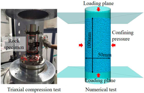
Figure 2. Numerical model of the diorite rock sample.
A Gaussian distribution was employed to assign strength values to the bonding material between particles in the numerical sample. Through repeated calculations, we obtained a set of microscopic parameters that reflect the macroscopic mechanical properties of the diorite samples under different confining pressures (Table 1). Figure 3 and Table 2 show the strength curves and failure results obtained from numerical and laboratory experiments under different confining pressures. The peak strengths of the samples obtained from experiments under different confining pressures agree well with the numerical values. Before the peak strength, the trends of the strength curves are consistent. After the peak strength, the experimental strength curves exhibit more distinct brittle characteristics than the numerically obtained curves, but the overall trends are consistent, indicating that the micromechanical parameters listed in Table 1 can be used for subsequent loading and unloading mechanical analyses.
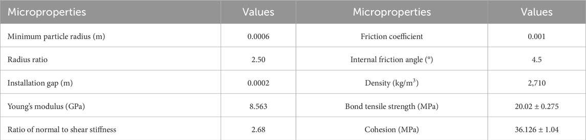
Table 1. Microproperties of the numerical model obtained using PFC3D.
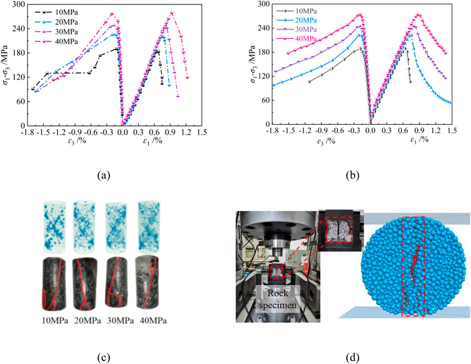
Figure 3. Experimental and numerical results under triaxial compression: (a) Experimental stress–stain curves; (b) Numerical stress-stain curves; (c) Failure modes under different confining pressures; (d) Experimental and numerical failure modes in the Brazilian splitting test.
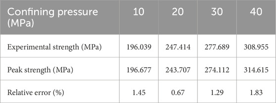
Table 2. Experimental and simulated peak strengths of rock samples under different confining pressures.
2.3 Unloading method
For numerical unloading analyses, the lateral rigid wall can be moved at a certain rate to unload the confining pressure on the samples (Jin et al., 2019). However, because of the increase in radial deformation during the unloading process, the confining pressure may first decrease and then increase. To avoid this shortcoming and improve the reliability of the involved method, we adopted a stress/time step unloading method, which can prevent the rebound of confining pressure during the unloading process, avoiding the uncertainty in the results.
In experimental analysis, the unloading method involves specifying a certain unloading rate (MPa/s) through servo control to obtain the specified unloading path. In numerical analysis, the stress/time step (MPa/Step) is employed to achieve the corresponding unloading path. Notably, the units of the unloading rate in the two methods are different. To ensure that the numerical unloading method has practical importance, determining the corresponding relation between these two unloading methods is necessary. Figure 4 shows the experimental and numerical unloading strength curves of a rock sample under a confining pressure of 30 MPa. The slopes of the experimental and numerical unloading strength curves are the same, indicating that the stress/time step unloading method used in numerical analysis is the same as the stress-control unloading method used in experiments.
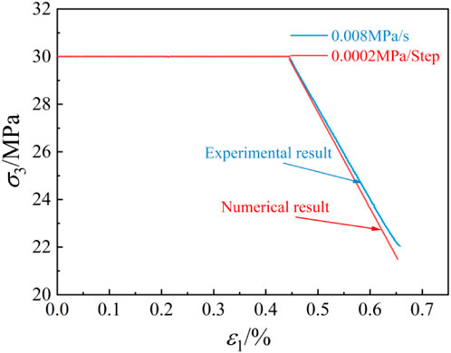
Figure 4. Experimental and simulated strain curves of a rock sample under a confining pressure.
2.4 Tested scheme
To investigate the influence of unloading rates on microscopic damage and fracture evolution in diorite, a numerical scheme was developed as follows (Figure 5): (I) a predetermined hydrostatic pressure of 30 MPa was applied to the diorite sample through servo control; (Ⅱ) the vertical servo control was turned off, a displacement rate of 0.0002 mm/step was assigned to the top and bottom walls of the sample, and the axial pressure was continuously applied; (Ⅲ) when the axial stress was applied to 80% of the peak strength, the confining pressure was unloaded at three rates (0.0002, 0.0004, and 0.0008 MPa/Step) while maintaining the axial loading rate until sample failure.
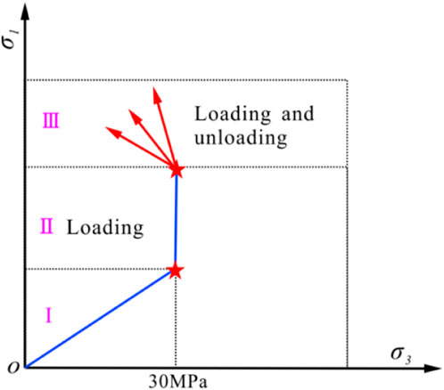
Figure 5. Schematic of the loading path.
3 Results and analysis
3.1 Regional division of the model
During the loading and unloading processes, macroscopic deformation of the sample primarily occurs in the axial and radial directions. In this study, the numerical model was divided into different regions (Figure 6). Hi and Ki (i = 1, 2, 3, 4, and 5) represent regions in the axial and radial directions of the specimen, respectively. The strength curve of the specimen under different unloading rates comprises a loading phase (Ⅱ) and a loading–unloading phase (Ⅲ). Next, the particle displacement, contact force chain, and microcrack evolution characteristics corresponding to the four key points (loading and unloading initial point A, loading and unloading point B (90% of peak strength), loading and unloading peak strength point C, and loading and unloading point D (60% of peak strength)) on the diorite strength curve shown in Figure 7 is studied. Notably, phase Ⅱ and Ⅲ in Figure 7 are elaborated in Section 2.3.
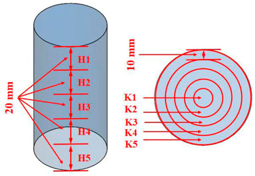
Figure 6. Regional division of the model.
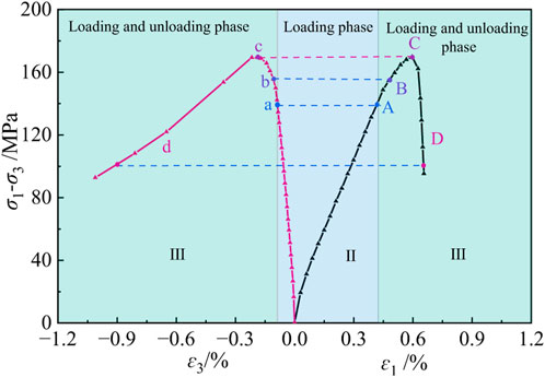
Figure 7. Key points on the loading and unloading strength curves.
3.2 Change characteristics of loading and unloading strength curves
Figure 8 presents the changes in the strength of diorite samples with the unloading confining pressure rate. As the unloading confining pressure rate decreases, the peak deviatoric stress increases, the postpeak deviatoric stress rapidly decreases, and the postpeak radial deformation rapidly increases (Figure 8a), consistent with the results of a previous study (Cong et al., 2023). Although the numerical models under the three unloading conditions are identical, their peak stresses differ. This is because the higher the unloading confining pressure rate, the lower the lateral deformation constraint of the rock sample, decreasing the bearing capacity of the rock sample.
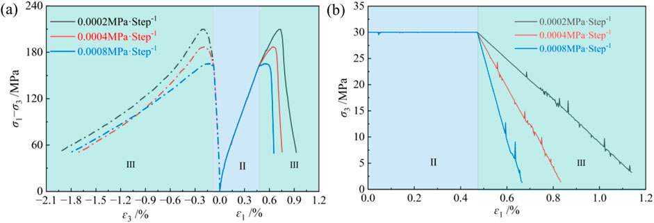
Figure 8. Strength curves of samples under different unloading confining pressure rates: (a) Strength curves; (b) Relationship between confining pressure and axial strain.
As shown in Figure 8b, with increasing unloading confining pressure rate, the slope of the unloading curve gradually increases and its trend is consistent with that reported in a previous study (Li et al., 2019). During the unloading process, the confining pressure and axial strain curves linearly decrease, but an instantaneous floating phenomenon occurs in the local part of the curve, which becomes more pronounced as the unloading process continues. This is because sudden fracture within the rock sample can cause an instantaneous decrease in the confining pressure, indicating that damage and fracture evolution in the rock sample is a progressive failure process.
3.3 Response characteristices of contact force chains
The numerical model obtained using PFC3D enables overlapping of rigid particles in mechanical relations, thereby effectively simulating the contact forces between particles. Particles form continuous or intermittent contact force chains with different strengths through contact and run through the entire specimen. During external loading, when the particle is subjected to a force greater than the ultimate load-bearing capacity of the force chain, fracture can occur. The number of contact force chain failures in the sample better reflects the degree of damage and fracture. Figure 9 presents the response curves of the number of contact force chain failures in the regions along the axial and radial directions of the specimen under different unloading confining pressure rates.
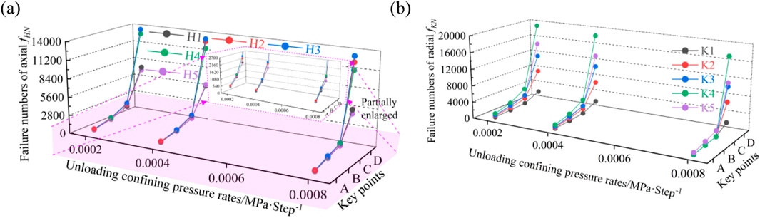
Figure 9. Response curves of contact force chains in the sample under different unloading confining pressure rates: (a) Number of contact force chain failures in different axial sections of the sample; (b) Number of contact force chain failures in different radial sections of the sample. fHN, number of contact force chain failures along the axial direction of the sample; fKN, number of contact force chain failures along the radial direction of the sample.
As shown in Figure 9, during the loading and unloading processes, the number of contact force chain failures in different axial and radial regions of the sample gradually increases and the number of contact force chain failures in different radial regions is considerably greater than the number in different axial regions. This indicates that while unloading the confining pressure, the change in lateral constraints leads to a greater change in stress in the radial direction inside the rock sample than in the axial direction. In addition, the number of contact force chain failures in the middle of the sample is higher than those at the end. This phenomenon may be related to the constraint effect of the axial loading plate on the end of the rock sample. The number of force chain failures in different regions of the rock sample increases with decreasing unloading confining pressure rate. This indicates that various contact stresses in the rock sample are transmitted and adjusted more fully over a longer time step at low unloading rates. This process allows particles to participate in stress adjustment and redistribution for longer periods, thereby increasing the number of internal contact force chain failures.
3.4 Response characteristics of particle displacements
To more intuitively and quantitatively evaluate the axial and radial response characteristics of particle displacement in the numerical model while unloading confining pressure, we derived the particle displacement components in each region of the sample corresponding to the four key points (A, B, C, and D) using a self-designed program and calculated the mean of all particle displacement components in the same region. Finally, the changes in the average particle displacement components in different regions of the sample under different unloading confining pressure rates were plotted (Figure 10).
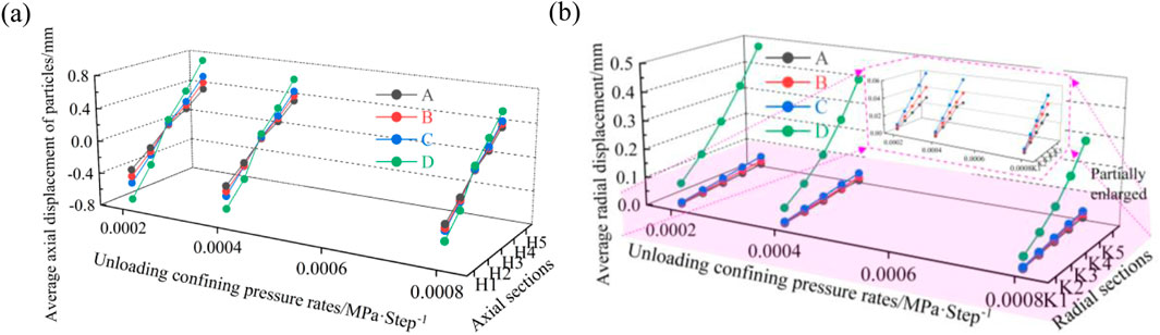
Figure 10. Particle displacements in the samples at different unloading confining pressure rates: (a) Axial displacement component; (b) Radial displacement component.
During the loading and unloading processes, the axial displacement components of particles at the upper and lower ends along the axial direction of the rock sample were larger than those in the middle (Figure 10), which is related to the direct external load borne by the particles at the upper and lower ends of the sample. The radial displacement components of particles along the radial direction of the rock sample showed a nonlinear concave increase from the inside out and gradually increased with further loading and unloading. This is because during the loading and unloading processes, as the confining pressure decreases, the lateral contact stress between particles inside the sample decreases and the particles are more prone to lateral displacement under compression, which results in greater volume expansion. Furthermore, the axial and radial displacement components of particles in different internal regions of the sample decreased with increasing unloading confining pressure rate. This indicates that as the unloading rate increases, the stress transfer and adjustment time between particles inside the sample become shorter, and the contact force between particles decreases, resulting in a decrease in the axial and radial deformation components of the particles.
3.5 Spatial distribution characteristics of microcracks
The distribution of tensile shear microcracks inside the diorite samples during loading and unloading is the most intuitive response to damage and fracture. Tables 3, 4 list the radial and axial distribution densities of internal tensile shear microcracks during the loading and unloading processes of the samples under different unloading confining rates, respectively.
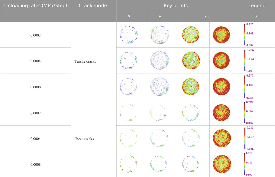
Table 3. Radial distribution density of tensile shear microcracks in the sample during the loading and unloading processes.
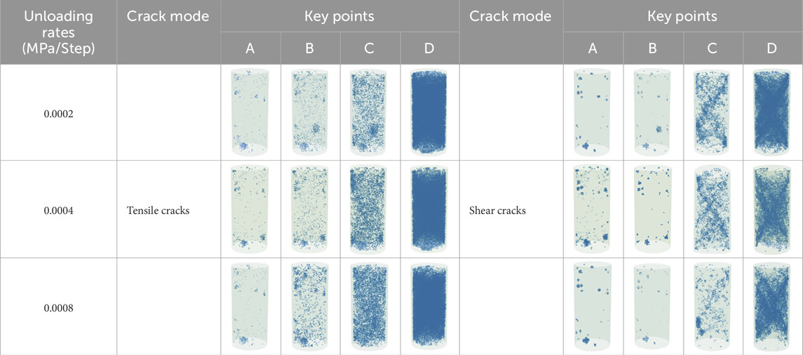
Table 4. Axial distribution of tensile shear microcracks in the specimen during loading and unloading.
As shown in Table 3, the internal microcracks of the samples under the three unloading-confining-pressure rates are primarily distributed near the unloading surface and gradually expand and evolve toward its interior as unloading continues, especially after the loading and unloading peak strength. The number of tensile microcracks caused by the lateral volume expansion of the sample is substantially higher than that of shear fracture microcracks, and the growth rate of tensile microcracks under unloading confining pressure is higher than that of shear microcracks. This is due to the concentration of contact tensile stress between particles near the unloading surface during the unloading process, which renders it easier for tensile cracks to form and expand.
As shown in Table 4, at key point A, radial tensile shear microcracks accumulate at the upper and lower ends of the sample under different unloading confining pressure rates. At key points B–D, the distribution of internal tensile cracks in the sample is similar to that at key point A before achieving the loading and unloading peak strength: internal tensile cracks are primarily distributed at the sample edges. After the loading and unloading peak strength, the distribution is more uniform along the axial direction; in addition, the distribution density increases with increasing unloading confining pressure rate. This indicates that during while unloading the confining pressure, the particles near the unloading surface are more susceptible to tensile stress, resulting in the formation of tensile cracks. The internal shear cracks of the sample accumulate at the sample edges before the loading and unloading peaks and at the double-shear part of the sample after the loading and unloading peaks. The distribution density decreases with increasing unloading confining pressure rate. The above results show that there is a difference in the failure shape of the specimens between the numerical and experimental analyses. This is because the material distribution inside the numerical samples is uniform and there are no natural defects, unlike in case of actual samples.
4 Discussion
The microscopic response characteristics within the macroscopic mechanical surface of a rock during the loading and unloading cycles are vital in understanding the mechanism of unloading damage and fractures in rock samples. Figure 11 presents the evolution mechanism of the loading and unloading damage and fracture of the sample.
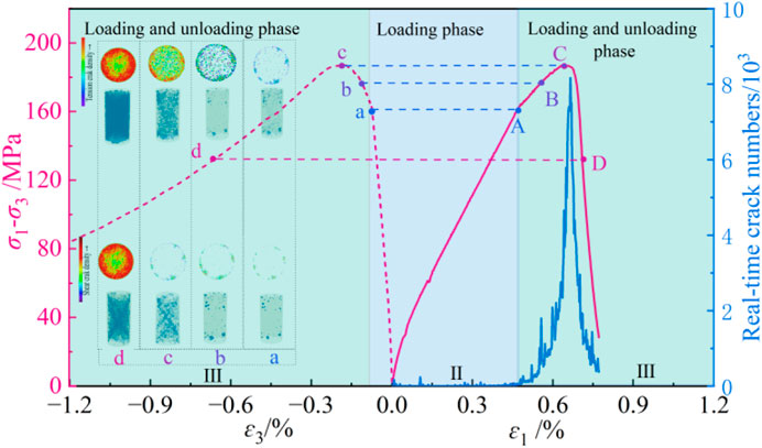
Figure 11. Evolution curve of damage and fracture in rock samples during loading and unloading processes.
Before achieving the loading and unloading peak strength (points A–C), owing to the compression effect at the upper and lower sample ends, the axial displacement component and tensile shear microcracks of particles near the ends are larger than those in the middle of the samples. In addition, because the tensile strength of the force chain between particles is smaller than their shear strength, tensile cracks generated inside the sample outnumber the shear cracks. During axial compression, particles in the rock sample move in the direction of the applied force and in the radial direction. Owing to the unloading confining pressure, the degree of obstruction to the radial movement of particles is weakened, especially near the unloading surface, resulting in more severe changes in the tensile and shear microcracks near the unloading surface compared to its interior. As loading and unloading continue, the damage and fracture of the sample gradually expand and penetrate from the edges and ends of the samples to the interior and middle. When the tensile shear main through the lateral surface of the sample is formed, the sample reaches its ultimate bearing capacity. After the loading and unloading peak strength (point C), as the bearing capacity and lateral constraint force of the sample rapidly decrease, shear slip occurs when the tensile shear microcracks near the main through surface accumulate to a certain extent, resulting in complete sample failure.
PFC is an effective tool for exploring the macroscopic and microscopic mechanical properties of rocks. It can be used to construct numerical models that are close to the mineral shape and gradation of actual rock materials. However, it leads to high computational costs. Thus, herein, we employed spherical particles to establish a scale of 50 mm × 100 mm for a standard cylindrical numerical sample. Considering that the internal scale ratio of common rock and soil materials ranges from 10–5 to 10–1 (Bazant and Chen, 1997; Yin et al., 2011), after repeated adjustments, the maximum particle diameter in the model was determined to be 1.5 mm, which is < 1/10 of the sample diameter, i.e., the internal scale is 10–2, which meets the requirements for the internal scale ratio of rock and soil materials.
Several studies on the microscopic response characteristics of rock samples under different unloading paths have been reported, but most of them are based on software interface output results (Amiri and Bahrani, 2024; Huang et al., 2019). In this study, we employed a self-designed program to output information on all particles, contact force chains, and tensile shear microcracks in a rock sample. Statistical analysis was then performed to analyze the evolution of this microscopic information along the axial and radial directions of the sample during the unloading confining pressure processes.
5 Conclusion
Herein, using PFC3D, we investigated the response characteristics of internal particle displacement, contact force chains, and tensile shear microcracks during the loading and unloading processes of diorite samples under three unloading confining pressures and determined the evolution mechanism of unloading damage and fracture of diorite at the macrolevel and microlevel. The main conclusions are as follows.
(1) As the unloading confining pressure rate decreases, the ultimate bearing capacity and peak strain of the rock sample increase. During the unloading process, the strain curve of the involved sample at a confining pressure shows notable instantaneous fluctuation. This indicates the gradual fracture evolution of the sample during loading and unloading.
(2) Under the three unloading confining pressures, the displacement of particles and the number of contact force chain failures in the sample show a nonlinear concave increase along the sample radial direction, especially after the peak strength, indicating that the unloading confining pressure considerably affects the damage and fracture of materials near the unloading surface.
(3) Before peak loading and unloading strength, the tensile and shear microcracks accumulate at the upper and lower ends of the sample and near the unloading surface. After the loading and unloading peak strength, the tensile cracks are evenly distributed along the axial direction of the sample, whereas shear cracks mainly accumulate at the double-shear position. The distribution density increases with decreasing unloading confining pressure rate, indicating relatively sufficient time for stress transfer and adjustment in the sample at low unloading-confining-pressure rates.
Data availability statement
The original contributions presented in the study are included in the article/supplementary material, further inquiries can be directed to the corresponding author.
Author contributions
XA: Data curation, Funding acquisition, Investigation, Writing – review and editing. JH: Data curation, Formal Analysis, Writing – review and editing. XD: Methodology, Supervision, Writing – original draft. DY: Investigation, Resources, Visualization, Writing – original draft.
Funding
The author(s) declare that financial support was received for the research and/or publication of this article. This work was supported by the Natural Science Basic Research Program of Shaanxi Province (2025JC-YBQN-014), Shaanxi College of Communications Technology Scientific Research Innovation Team Funding Project (CX2302), Shaanxi Provincial Education Department Scientific Research Program Key Project (24JR025) and Shaanxi Provincial Department of Education Youth Innovation Team Project (24JP017). Their support is gratefully acknowledged.
Conflict of interest
The authors declare that the research was conducted in the absence of any commercial or financial relationships that could be construed as a potential conflict of interest.
The reviewer RL declared a shared affiliation with the author WZ to the handling editor at the time of review.
Generative AI statement
The author(s) declare that no Generative AI was used in the creation of this manuscript.
Publisher’s note
All claims expressed in this article are solely those of the authors and do not necessarily represent those of their affiliated organizations, or those of the publisher, the editors and the reviewers. Any product that may be evaluated in this article, or claim that may be made by its manufacturer, is not guaranteed or endorsed by the publisher.
References
Amiri, F., and Bahrani, N. (2024). Continuum-based heterogenous models for capturing brittle damage and failure of hard rocks under loading and unloading conditions. Comput. Geotechnics 165, 105917. doi:10.1016/j.compgeo.2023.105917
An, X. X., Hu, Z. P., Zhang, L., Liu, A. L., Zhang, Y. H., and Li, F. (2022). Nonlinear energy evolution characteristics of diorite examined by triaxial loading-unloading and acoustic emission tests. Materials 15 (18), 6434. doi:10.3390/ma15186434
An, X. X., Su, Y., Tao, L., Tian, A. A., and Hu, Z. P. (2023). Analysis of pre-peak strain energy storage transformation mechanism of diorite under triaxial loading-unloading paths. Bull. Eng. Geol. Environ. 82 (7), 270. doi:10.1007/s10064-023-03310-4
Ao, Y. H., Jia, B. X., Sun, C., Chen, D. X., and Pu, Y. B. (2024). Rockburst proneness analysis of rock materials based on the discrete element method. Eng. Analysis Bound. Elem. 169, 106047. doi:10.1016/j.enganabound.2024.106047
Bazant, Z. P., and Chen, E. P. (1997). Scaling of structural failure. Appl. Mech. Rev. 50 (10), 593–627. doi:10.1115/1.3101672
Bing, D., Zhao, G. Y., Konietzky, H., and Wasantha, P. L. P. (2018). Experimental and numerical study on the damage evolution behaviour of granitic rock during loading and unloading. Ksce J. Civ. Eng. 22 (9), 3278–3291. doi:10.1007/s12205-018-1653-7
Chen, M., Yang, S. Q., Ranjith, P. G., and Zhang, Y. C. (2020a). Cracking behavior of rock containing non-persistent joints with various joints inclinations. Theor. Appl. Fract. Mech. 109, 102701. doi:10.1016/j.tafmec.2020.102701
Chen, X. D., Tang, J. H., Zhang, N., Dai, F., and Wei, M. D. (2022). Fracture analysis of three-point bending notched granite beams under prepeak and postpeak cyclic loading by digital image correlation and acoustic emission techniques. Fatigue and Fract. Eng. Mater. and Struct. 45 (3), 904–920. doi:10.1111/ffe.13646
Chen, Y., Zuo, J. P., Li, Z. H., and Dou, R. (2020b). Experimental investigation on the crack propagation behaviors of sandstone under different loading and unloading conditions. Int. J. Rock Mech. Min. Sci. 130, 104310. doi:10.1016/j.ijrmms.2020.104310
Cong, Y., Cong, Y., Zhang, L. M., Jia, L. X., and Wang, Z. Q. (2019). 3D particle flow simulation of loading-unloading failure process of marble. Rock Soil Mech. 40 (3), 1179–1186. doi:10.16285/j.rsm.2018.0262
Cong, Y., Yuan, H. C., Abi, E. D., Han, Y. F., Li, H. T., and Pu, Y. J. (2023). Deformation and acoustic emission characteristics of hard rock under different unloading rates. Alexandria Eng. J. 77, 581–591. doi:10.1016/j.aej.2023.06.056
De Silva, V. R. S., Ranjith, P. G., Wu, B., and Perera, M. S. A. (2018). Micro-mechanics based numerical simulation of NaCl brine induced mechanical strength deterioration of sedimentary host-rock formations. Eng. Geol. 242, 55–69. doi:10.1016/j.enggeo.2018.05.005
Han, Y., Ma, H., Yang, C., Li, H., and Yang, J. (2021). The mechanical behavior of rock salt under different confining pressure unloading rates during compressed air energy storage (CAES). J. Petroleum Sci. Eng. 196, 107676. doi:10.1016/j.petrol.2020.107676
He, X., He, Y., Guo, L., Pan, X. H., Pang, C. X., Qiao, L., et al. (2018). Development of softening constitutive model based on Flat-Joint contact model and parametric analysis. Chin. J. Rock Mech. Eng. 37 (10), 2277–2287. doi:10.13722/j.cnki.jrme.2018.0007
Huang, Y. H., Yang, S. Q., and Tian, W. L. (2019). Crack coalescence behavior of sandstone specimen containing two pre-existing flaws under different confining pressures. Theor. Appl. Fract. Mech. 99, 118–130. doi:10.1016/j.tafmec.2018.11.013
Jin, A. B., Liu, J. W., Zhao, Y. Q., Wang, B. X., Sun, H., and Wei, Y. D. (2019). Mechanical characteristics analysis of granite under unloading conditions. Rock Soil Mech. 40, 459–467. doi:10.16285/j.rsm.2018.1920
Lau, J. S. O., and Chandler, N. A. (2004). Innovative laboratory testing. Int. J. Rock Mech. Min. Sci. 41 (8), 1427–1445. doi:10.1016/j.ijrmms.2004.09.008
Li, B. Y., Yang, F. W., Li, H. F., Du, P. Z., and Liu, Z. H. (2023). Experimental study on triaxial unloading mechanical properties and acoustic emission response of shale with different water contents. Environ. Earth Sci. 82 (18), 414. doi:10.1007/s12665-023-11124-6
Li, X. B., Chen, Z. H., Weng, L., and Li, C. J. (2019). Unloading responses of pre-flawed rock specimens under different unloading rates. Trans. Nonferrous Metals Soc. China 29 (7), 1516–1526. doi:10.1016/s1003-6326(19)65059-4
Li, Y. P., Zhang, Q., and Jiang, B. S. (2024). Numerical investigation on the mechanical and fracture behaviors of marble under cyclic loading and unloading true triaxial compression using discrete element method. Comput. Part. Mech. 11 (6), 2753–2776. doi:10.1007/s40571-024-00750-x
Lin, H., Liu, J., Yang, J., Ran, L. N., Ding, G. S., Wu, Z. D., et al. (2022). Analysis of damage characteristics and energy evolution of salt rock under triaxial cyclic loading and unloading. J. Energy Storage 56, 106145. doi:10.1016/j.est.2022.106145
Liu, J., Zhang, C. G., Oh, J., Canbulat, I., Li, C. C., Craig, P., et al. (2024). Microcrack characteristics of granite under circumferential strain-controlled uniaxial compression test using UDEC-GBM. Comput. Geotechnics 174, 106627. doi:10.1016/j.compgeo.2024.106627
Potyondy, D. O., and Cundall, P. A. (2004). A bonded-particle model for rock. Int. J. Rock Mech. Min. Sci. 41 (8), 1329–1364. doi:10.1016/j.ijrmms.2004.09.011
Rong, H. Y., Li, G. C., Liang, D. X., Xu, J. H., and Hu, Y. Q. (2022). Particle flow simulation of mechanical properties of high stress rock under the influence of stress path. J. Min. Saf. Eng. 39 (1), 163–173. doi:10.13545/j.cnki.jmse.2021.0191
Shen, J. Y., Sun, C. H., Huang, H. J., Chen, J. W., and Wu, C. Z. (2023). Scale effects on shear strength of rough rock joints caused by normal stress conditions. Sustainability 15 (9), 7520. doi:10.3390/su15097520
Tang, J. H., Chen, X. D., Dai, F., and Wei, M. D. (2020). Experimental investigation of fracture damage of notched granite beams under cyclic loading using DIC and AE techniques. Fatigue and Fract. Eng. Mater. and Struct. 43 (7), 1583–1596. doi:10.1111/ffe.13253
Wang, H. Y., Dyskin, A., Dight, P., Pasternak, E., and Hsieh, A. (2020a). Review of unloading tests of dynamic rock failure in compression. Eng. Fract. Mech. 225, 106289. doi:10.1016/j.engfracmech.2018.12.022
Wang, S. S., Xu, W. Y., Yan, L., Feng, X. T., Xie, W. C., and Chen, H. J. (2020b). Experimental investigation and failure mechanism analysis for dacite under true triaxial unloading conditions. Eng. Geol. 264, 105407. doi:10.1016/j.enggeo.2019.105407
Wang, Y., Zhao, Q. H., Xiao, Y. G., and Hou, Z. Q. (2020c). Influence of time-lagged unloading paths on fracture behaviors of marble using energy analysis and post-test CT visualization. Environ. Earth Sci. 79 (10), 217. doi:10.1007/s12665-020-08945-0
Wu, S. C., and Xu, X. L. (2016). A study of three intrinsic problems of the classic discrete element method using flat-joint model. Rock Mech. Rock Eng. 49 (5), 1813–1830. doi:10.1007/s00603-015-0890-z
Wu, Y., Wang, D. K., Wang, L., Shang, S. J., Zhu, C. Q., Wei, J. P., et al. (2022). An analysis of the meso-structural damage evolution of coal using X-ray CT and a gray-scale level co-occurrence matrix method. Int. J. Rock Mech. Min. Sci. 152, 105062. doi:10.1016/j.ijrmms.2022.105062
Xiong, L. X., Xu, Z. Y., Li, B., and Zhang, Y. (2019). Bonded-particle discrete element modeling of mechanical behaviors of interlayered rock mass under loading and unloading conditions. Geomechanics Geophys. Geo-Energy Geo-Resources 5 (1), 1–16. doi:10.1007/s40948-018-0090-x
Yang, P., Pang, D. D., Liu, J., Huang, Z. G., Xu, W. S., and Dou, Z. S. (2023). Experiment on deformation and failure characteristics of sandstone at different unloading rates. Alexandria Eng. J. 75, 209–219. doi:10.1016/j.aej.2023.05.061
Yang, S. Q., Yin, P. F., Zhang, Y. C., Chen, M., Zhou, X. P., Jing, H. W., et al. (2019). Failure behavior and crack evolution mechanism of a non-persistent jointed rock mass containing a circular hole. Int. J. Rock Mech. Min. Sci. 114, 101–121. doi:10.1016/j.ijrmms.2018.12.017
Yang, Y. Z., and Zhang, Z. N. (2020). Dynamic fracturing process of fissured rock under abrupt unloading condition: a numerical study. Eng. Fract. Mech. 231, 107025. doi:10.1016/j.engfracmech.2020.107025
Yin, X. I. T., Zheng, Y. N., and Ma, S. K. (2011). Study of inner scale ratio of rock and soil material based on numerical tests of Particle flow code. Rock Soil Mech. 32 (34), 1211–1215. doi:10.16285/j.rsm.2011.04.017
You, S., Li, H. Z., Hou, X. X., and Geng, Q. C. (2023). Deformation damage characteristics and evolution mechanism of granite under mining stress path. J. Northeast. Univ. 44 (8), 1177–1187. doi:10.12068/j.issn.1005-3026.2023.08.015
Zhang, C., Fu, J. X., and Wang, Y. (2023a). Numerical simulation of true triaxial unilateral unloading effect of fractured rock. Eng. Comput. 40 (9/10), 2110–2128. doi:10.1108/ec-07-2022-0477
Zhang, S. G., Li, Y. M., Yang, J. F., Song, Y., Yang, L., and Guo, J. H. (2023b). Energy action mechanism of reinforced sandstone under triaxial cyclic loading and unloading. Materials 16 (1), 211. doi:10.3390/ma16010211
Zhang, X. P., and Wong, L. N. Y. (2012). Cracking processes in rock-like material containing a single flaw under uniaxial compression: a numerical study based on parallel bonded-particle model approach. Rock Mech. Rock Eng. 45 (5), 711–737. doi:10.1007/s00603-011-0176-z
Zhao, H. G., Song, Z. L., Zhang, D. M., Liu, C., and Yu, B. C. (2021). True triaxial experimental study on mechanical characteristics and energy evolution of sandstone under various loading and unloading rates. Geomechanics Geophys. Geo-Energy Geo-Resources 7 (1), 22. doi:10.1007/s40948-020-00212-7
Zhao, K., Ma, H. L., Liang, X. P., Li, X. X., Liu, Y. B., Cai, R., et al. (2022). Damage evaluation of rock salt under multilevel cyclic loading with constant stress intervals using AE monitoring and CT scanning. J. Petroleum Sci. Eng. 208, 109517. doi:10.1016/j.petrol.2021.109517
Keywords: numerical analysis, loading and unloading, particle displacement, contact force chain failure, microcrack evolution
Citation: An X, Huang J, Duan X and Yang D (2025) Effect of unloading confining pressure rates on macroscopic and microscopic mechanisms in diorite based on PFC3D. Front. Mater. 12:1550403. doi: 10.3389/fmats.2025.1550403
Received: 23 December 2024; Accepted: 07 April 2025;
Published: 27 June 2025.
Edited by:
Changtai Zhou, City University of Hong Kong, Hong Kong SAR, ChinaReviewed by:
Yunliang Tan, Shandong Univeristy of Science and Technology, ChinaJiarong Chen, Central South University, China
Rui Li, Xi’an University of Science and Technology, China
Copyright © 2025 An, Huang, Duan and Yang. This is an open-access article distributed under the terms of the Creative Commons Attribution License (CC BY). The use, distribution or reproduction in other forums is permitted, provided the original author(s) and the copyright owner(s) are credited and that the original publication in this journal is cited, in accordance with accepted academic practice. No use, distribution or reproduction is permitted which does not comply with these terms.
*Correspondence: Xuexu An, MjAxOTAyODAxMkBjaGQuZWR1LmNu;