 Jin Yu1
 Tianwei Kong
- 1CNOOC Gas and Power Group Ltd., Beijing, China
- 2College of Mechanical and Transportation Engineering, National Engineering Research Center for Pipeline Safety, MOE Key Laboratory of Petroleum Engineering, Beijing Key Laboratory of Urban Oil and Gas Distribution Technology, China University of Petroleum-Beijing, Beijing, China
The growing demand for lightweight, corrosion-resistant, and cost-effective solutions in offshore oil and gas operations has driven the transition from traditional metallic pipes to advanced non-metallic flexible pipes. A rigorous three-dimensional nonlinear finite element model was developed using ABAQUS/Explicit, incorporating actual material parameters, structural nonlinearity, and interlayer contact behavior. The model was validated through full-scale burst pressure tests, demonstrating excellent agreement (within 13.4% error) with experimental results. Key findings indicate that internal pressure of 35 MPa can increase tensile stiffness by up to 22.1%, while external pressure of 15 MPa enhances it by 8.9%. Under combined axial tension-bending loading conditions, the flexible pipe demonstrates higher bending stiffness compared to single-load scenarios. Internal pressure exhibits minimal influence on non-slip bending stiffness but simultaneously elevates both critical slip curvature and post-slip stiffness. In contrast, external pressure significantly improves both critical slip curvature and post-slip stiffness. These quantitative results provide crucial design guidelines for performance optimization of non-metallic pipes in deepwater applications.
1 Introduction
In recent years, composite materials have been widely adopted in engineering applications, particularly in deep-sea oil and gas exploration, where flexible pipes have become essential infrastructure for offshore hydrocarbon transportation. These pipes are often referred to as the “lifeline” of offshore oil and gas resources due to their critical role in production systems. The mechanical analysis of flexible pipes under load is primarily conducted using numerical simulation methods and experimental approaches. In numerical modeling, researchers have focused on developing accurate representations of key functional layers. De Sousa established a finite element model of a 4-inch flexible pipe considering the nonlinearity of metallic materials using ANSYS software. In this model, the spiral strips in the tensile armor layer were simulated using beam elements, the carcass layer and the pressure armor layer were simulated using orthotropic shell elements, and the remaining cylindrical layers were simulated using isotropic shell elements (De Sousa et al., 2018). Sævik utilized the specialized finite element software BFLEX to simulate the compression armor layer and calculate the stress distribution of the Z-shaped helical strip under internal pressure, tensile, and bending loads. Additionally, a complete model of the flexible pipe was established in BFLEX to simulate the stress in the helical strip of the tensile armor layer under bending loads, and the validity of the model was confirmed through experimental results (Sævik and Thorsen, 2012). Zhou and Sævik, among others, investigated the mechanical properties of a multilayer flexible pipe, replacing the metallic compression reinforcement layer with an epoxy composite carbon fiber (EP/CF) material. They developed a finite element model using ABAQUS to analyze the stress state of various functional layers under axial tensile and bending loads for the new structural flexible pipe (Zhou et al., 2017). Lukassen proposed a finite element model using a representative unit cell (RUC) to study the mechanical performance of flexible pipes under axial tensile and bending loads. By establishing periodic boundary conditions based on the periodicity of the flexible pipe structure and loads, the stress distribution of the local tensile reinforcement layer was solved (Lukassen et al., 2019). However, extensive research on numerical simulation of composite structures has also been conducted by other scholars. Venkadesh Raman et al. successfully identified critical failure zones in wind turbine blades through finite element analysis, and their interlayer contact model provides an important reference for the mechanical behavior analysis of non-metallic flexible pipes in this study (Venkadesh et al., 2016). Avachat systematically investigated the dynamic response characteristics of metal/composite hybrid structural plates subjected to underwater shock loading, employing experimental methods coupled with the Coupled Eulerian-Lagrangian (CEL) approach (Avachat and Zhou, 2016). Li et al. adopted a multi-scale simulation method to achieve comprehensive numerical simulation of the fiber-bundle-laminates’ mechanical properties and penetration resistance across micro-, meso-, and macro-scales throughout the entire deformation process (Li et al., 2025).
The establishment of numerical simulation models for flexible pipes is closely linked to the validation of real experimental results. To clarify the mechanical performance and failure modes of flexible pipes under various loads, experimental research is an indispensable and crucial method. Currently, the most cited experimental study is Witz’s re-search from 1996 on a 2.5-inch unbonded flexible pipe, which primarily investigates the mechanical performance of flexible pipes under axial tensile loads, torsional loads, and bending loads. The study provides detailed geometric and material parameters of the test samples (Witz, 1996). Clevelario and others conducted experiments on the crushing failure of flexible pipes un-der bending loads, utilizing samples with internal diameters of 4 inches and 6 inches. In their experiments, the sample pipes were bent to 1.5 times the minimum bend radius while applying external compressive loads to study the crushing failure of the bent flexible pipes. The results indicated that the compressive stiffness of the flexible pipes de-creased by over 10% after bending deformation (Clevelario et al., 2010). De Sousa and colleagues performed experimental studies on the structural responses of 4-inch flexible pipes under various loads, obtaining data on structural stiffness, strains of the outer helical strips, failure loads, and failure modes for different loading conditions. They also conducted tensile tests on high-strength fiber materials designed to prevent radial buckling of the tensile armor layer’s helical strips (De Sousa, 2001).
Currently, research primarily focuses on metallic flexible pipes, with relatively few studies addressing non-metallic flexible pipes, such as those with high-strength fiber reinforcement and composite material functional layers. Due to significant differences in structural forms and material properties of the functional layers, their mechanical responses under various loads differ as well. Therefore, conclusions drawn from studies on metallic flexible pipes cannot be directly applied to non-metallic flexible pipes. It is essential to conduct numerical simulation studies specifically targeting the structural and material characteristics of the functional layers in non-metallic flexible pipes.
In this paper, a three-dimensional finite element model of flexible pipe was developed by ABAQUS/Explicit, which take the real material parameters, structural nonlinearity as well as the nonlinear contact behavior between components into account. Full-scale pipeline mechanical performance tests are conducted. The mechanical behavior of non-metallic unbonded flexible pipe subjected to combined load was investigated in detail. The stiffness change rule of flexible pipe under different loads is obtained. The findings and conclusions of current study would provide useful guides to the design and manufacturing of nonmetallic unbonded flexible pipe.
2 Nonlinear finite element model
2.1 Structure and parameters
The schematic diagram of the functional layers of the non-metallic non-bonded flexible pipe is shown in Figure 1. Unlike conventional metallic flexible pipes, the internal pressure reinforcement layer and tensile reinforcement layer of the non-metallic non-bonded flexible pipe are made of high-modulus aramid fibers, while the external pressure reinforcement layer is composed of carbon fiber reinforced nylon materials. The primary load-bearing functional layers are all made from non-metallic materials. The various functional layers of the pipe are not bonded with each other, allowing for relative slippage and friction under marine conditions. A three-dimensional solid model of the non-metallic non-bonded flexible pipe was established using the ABAQUS finite element analysis software. This model includes the S-shaped cross-section structure of the self-locking external pressure reinforcement layer, the internal pressure reinforcement layer woven from aramid fibers, the tensile reinforcement layer, and the corresponding polymer layers, with a non-bonded configuration between adjacent layers, as illustrated in Figure 2A. The internal pressure reinforcement layer and tensile reinforcement layer are modeled by composite material lamination model, which can simulate the braided angle and ply thickness of the fiber accurately. The braided angle of internal pressure reinforcement layer is 55° and the winding angle of tensile reinforcement layer is 30°. The length of the model is setup as 1640 mm to eliminate the end effects. The material parameters for each functional layer are presented in Table 1 (Wang et al., 2021).
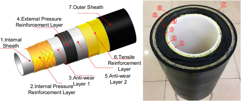
Figure 1. Schematic diagram of nonmetallic unbonded flexible pipe.
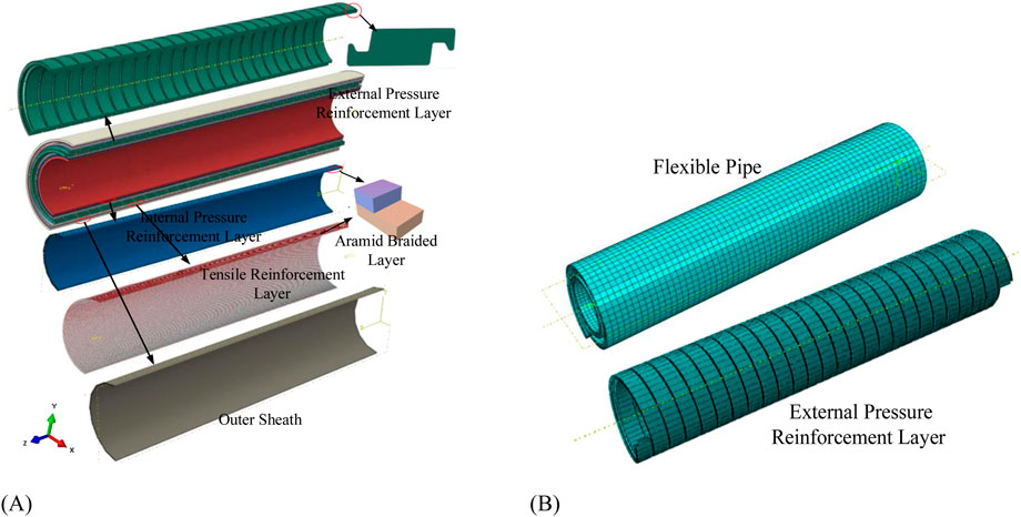
Figure 2. Finite element model and meshing schematic diagram: (A) FEM schematic diagram. (B) Mesh of the FEM.
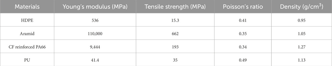
Table 1. Material parameters of nonmetallic unbonded flexible pipe.
2.2 Boundary conditions
The flexible pipe will be subjected to various forms of loads in the marine environment. To apply the loads and boundary conditions, reference points RP-1 and RP-2 are established at both ends of the flexible pipe. The “kinematic coupling” method was employed to couple both ends of the pipe with reference points (RP-1 and RP-2), ensuring that the degrees of freedom at the pipe ends match those of the reference points (Yang et al., 2015). The boundary conditions are applied at the reference points. The form of the boundary conditions for the finite element model analyzing the mechanical performance of the non-metallic flexible pipe is presented in Table 2.
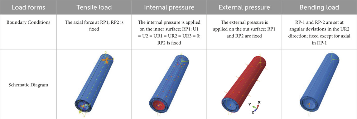
Table 2. Boundary conditions of nonmetallic unbonded flexible pipe.
2.3 Contact behaviors and mesh
The normal behavior of contact between layers is defined as “hard contact” with the setting of “allow separation after contact.” The tangential contact behavior is defined as “penalty,” with a friction coefficient set to 0.1 (Dai et al., 2017). A friction coefficient (CoF) of 0.1 was selected based on prior studies on non-bonded composite structures (Dai et al., 2017), which reported typical CoF values between thermoplastic layers. Sensitivity analysis shows that increasing CoF to 0.2 increases tensile stiffness by 4.7%, while decreasing it to 0.05 reduces stiffness by 3.2%. This confirms the model’s robustness and the chosen CoF’s rationalisation (reasonableness) for representing interlayer friction in nonmetallic materials. The numerical modeling approach employed distinct meshing strategies and element formulations for different pipe layers. A systematic mesh sensitivity study was conducted to establish appropriate element sizes that achieve an optimal balance between solution accuracy and computational cost for each functional component. The inner sheath, abrasion layer, external pressure reinforcement layer, and outer sheath are modeled using solid elements C3D8R (8-node hexahedron linear reducing integral element), with the thickness direction of the inner and outer layers divided into four elements. These elements are suitable for nonlinear analysis and can produce high-accuracy results when considering contact and nonlinear geometry (Ebrahimi et al., 2018). The mesh size is set to 15 mm in the axial direction, with 48 elements in the circumferential direction, while the external pressure reinforcement layer is assigned a global mesh size of 15 mm, and the S-shaped cross-section is refined using a sweeping method. The internal pressure reinforcement layer and tensile reinforcement layer are modeled using continuous shell elements SC8R (8-node quadrilateral general continuous shell elements), allowing for the simulation of the laminate arrangement. The axial dimension of the pipeline is 15 mm, and the circumferential direction is divided into 48 elements. This element size ensures the accuracy of the computations. The model comprises 232,755 elements, as shown in Figure 2B.
3 Full-scale bursting experiments
3.1 Specimen and experiment process
The internal pressure reinforcement layers and tensile reinforcement layers are modeled by composite material ply structure. To verify the accuracy and effectiveness of the above modeling approach, two groups of internal pressure bursting tests (one specimen pipeline for each group) of aramid fiber reinforcement thermoplastic pipes were conducted according to the API SPEC 17E standard (API, 2017). The 1-inch flexible pipe which produced by Beijing Zhongshida petrochemical technology development Co. Ltd were selected for the internal pressure bursting test. The flexible pipe specimen is shown as Figure 3A. The effective length of pipe is 800 mm (21 times of its outer diameter) and the end fittings (240 mm) are assembled by the withhold machine, rendering a sealing function. The end fittings were installed at both ends of the flexible pipe, where one end was fixed at the pressure port and the other end was free. The aramid fiber-reinforced thermoplastic pipes used in the internal pressure burst test consist of three functional layers: an internal liner made of Nylon 11 (PA11), a fiber reinforcement layer with a braided structure of aramid fibers at a weave angle of ±55°, and an external protective layer made of polyurethane, as illustrated in Figure 3B. The parameters of the flexible pipe are shown in Table 3. The bursting pressure can be obtained by gradually increasing the internal pressure till flexible pipe bursts or leaks.
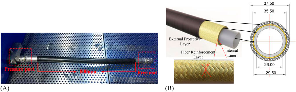
Figure 3. 1-inch aramid fiber reinforcement thermoplastic pipe (Unit:mm): (A) Specimen with end-fittings. (B) Pipeline structure diagram.
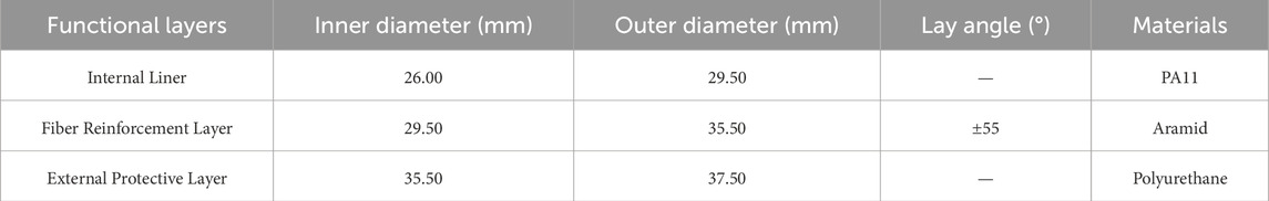
Table 3. Geometric parameters of 1 - inch aramid fiber reinforcement thermoplastic pipe.
3.2 Experiment results
Two sets of experiments were conducted, during which the aramid fiber-reinforced layers experienced rupture under internal pressure, leading to the failure of both the inner and outer layers of the pipeline. Figure 4 illustrates the time-pressure relationships for the two tests. The trend of increasing internal pressure was largely consistent. When the in-ternal pressure reached the burst pressure, the time-pressure curve exhibited a sharp de-cline, indicating leakage of the pipeline. The burst and leakage pressures of the hose in the two experiments were 78.2 MPa and 76.1 MPa, respectively.
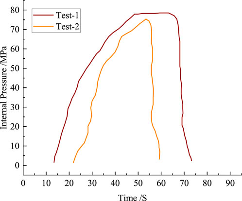
Figure 4. The time-pressure curves during the internal pressure experiments.
3.3 Model validation
Based on the internal pressure burst test results, a finite element analysis model was established to validate the accuracy of the numerical model. The fiber reinforcement layer is modeled by composite material ply structure, the braided angle and thickness of rein-forced layers are same with the specimen. The internal liner and external protective layer are modeled as solid structures based on their real geometric parameters, with material parameters referenced from Table 3. Using Chamis micromechanics equations, various anisotropic mechanical properties parameters of the aramid fiber composite material can be calculated (Qu, 2009). Specific parameters are shown in Table 4. The head plate is coupling on one end of flexible pipe to apply the head force (as shown in Figure 5). A pressure of 78.2 MPa is applied on the internal surface and head plate (Wang et al., 2019). The equivalent tensile strength of the aramid fiber bundle is 662 MPa, and the ultimate tensile strength of the matrix material of the composite laminate is 24.7 MPa. The failure of fiber reinforcement layer can be analyzed with the maximum stress criterion (given by Equation 1) of composite materials (Cornacchia et al., 2019).

Table 4. Anisotropic material parameters of aramid fiber reinforcement layer.
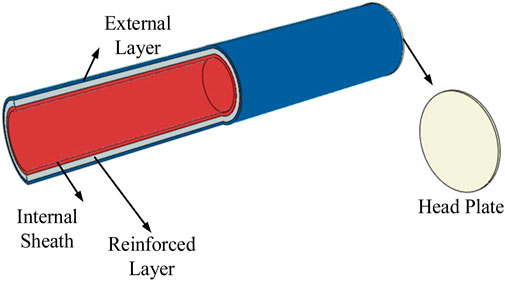
Figure 5. Internal pressure burst test model.
By applying a burst pressure of 78.2 MPa to the model and comparing the failure criterion coefficient (MSTRS), we observed that while the experimental failure corresponds to MSTRS = 1, our FEM (Finite Element Model) simulation yielded MSTRS = 1.13. The resulting 13.4% error margin adequately demonstrates the model’s accuracy. Although strain data were not directly compared, the fact that both kinetic energy and pseudo-strain energy remain below 5% of the total internal energy further confirms the model’s stability (as shown in Figure 6). This also ensures the numerical results remain unaffected by inertial effects, which is an essential requirement for conducting quasi-static analysis (Ren et al., 2018).
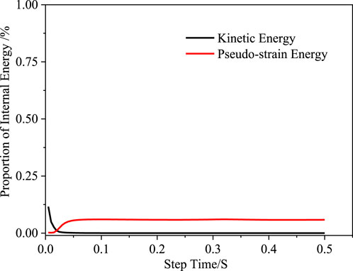
Figure 6. The proportion of kinetic energy and pseudo-strain energy in internal energy.
4 Mechanical behaviors of flexible pipe under different loads
According to API 17J specifications, the stiffness coefficients and mechanical properties of flexible risers under internal pressure, axial tension, and external pressure loads constitute critical parameters for both design/manufacturing processes and the establishment of integrated riser analysis models. Accordingly, this study systematically simulated: (1) individual loads (internal/external pressure, tension, bending) and (2) combined load cases including axial tension + internal pressure, axial tension + external pressure, and bending + internal/external pressure. These loading conditions accurately replicate the actual stress states encountered during deepwater operations.
4.1 Individual loads
4.1.1 Internal pressure load
The distribution of Von Mises stress (referred as stress in the following content) in the flexible pipe under an internal pressure of 35 MPa is shown in Figure 7. It can be seen that under the internal pressure, the stress in the internal pressure reinforcement layer is the highest among all functional layers, reaching to 417.5 MPa. Additionally, due to the material and structural differences, the stress distribution is very different for each functional layer. The maximum stress in the non-metallic reinforcement layer (417.5 MPa) is approximately 18% lower than that reported by De Sousa et al. (2018) for metallic pipes. This difference is mainly due to the lower elastic modulus of aramid fibers (110 GPa) compared to steel (210 GPa), but the specific strength of aramid is higher, meeting the lightweight requirements for deep-water applications.
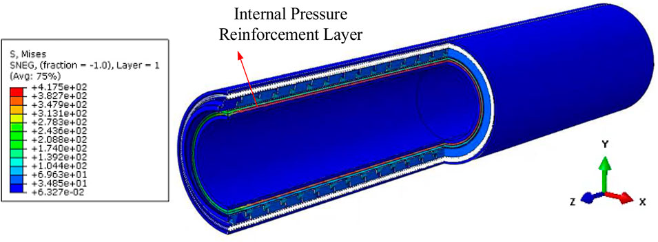
Figure 7. Von Mises stress distribution in the nonmetallic unbonded flexible pipe under 35 MPa internal pressure.
In order to further investigate the mechanical performance and bearing capacity of each functional layer of the flexible pipe under the action of internal pressure, stress plots of each functional layer are extracted separately, as shown in Figures 8A,B. The in-ternal pressure reinforcement layer primarily bears the internal pressure load. The maxi-mum stress of the aramid fibers in the internal pressure reinforcement layer 1 differs by 20 MPa from that in the internal pressure reinforcement layer 2. This is because the internal pressure reinforcement layer 1 is located on the internal side, and under the action of the internal pressure, its deformation is relatively larger. The tensile reinforcement layer on the external side of the external pressure reinforcement layer bears relatively smaller load.
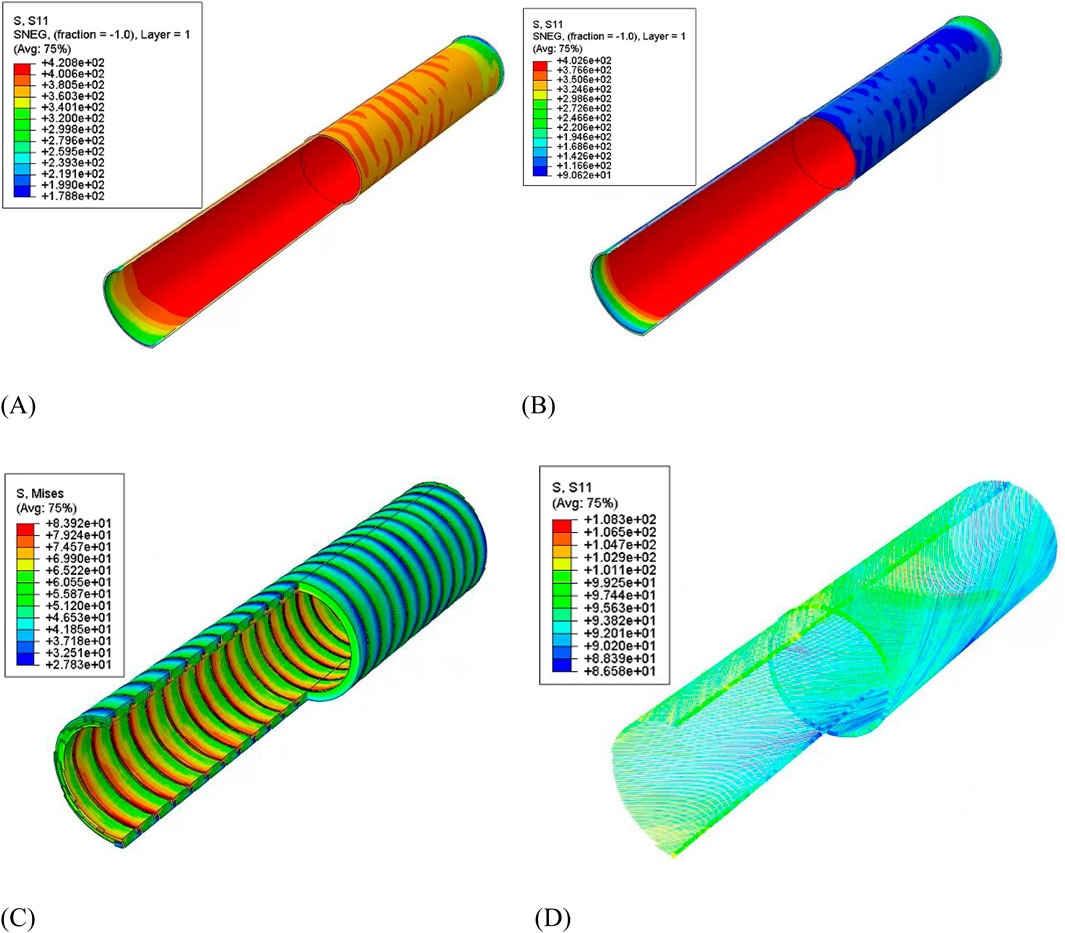
Figure 8. Stress of each functional layer under internal pressure: (A) Internal pressure reinforcement layer 1. (B) Internal pressure reinforcement layer 2. (C) External pressure reinforcement layer. (D) Tensile reinforcement layer.
Under the action of internal pressure, the maximum stress of the external pressure reinforcement layer is located on the internal side, close to the surface of the internal pressure reinforcement layer. The maximum stress is 83.9 MPa. Due to its S-shaped cross-section with spiral-wrapped strips, it has relatively large radial stiffness, allowing it to withstand certain internal pressure. Under 35 MPa internal pressure, the tensile reinforcement layer will experience stress along the direction of the fiber bundle, with the maximum stress of the fiber being 108.3 MPa. This is because under the action of internal pressure, the flexible pipe undergoes radial and axial deformation, and the tensile reinforcement layer is subjected to tensile load.
The trend of maximum stress in the internal pressure reinforcement layer with the change in internal pressure is shown in Figure 9A. From the figure, it can be observed that the maximum stress of the aramid fibers in the internal pressure reinforcement layer in-creases linearly with the increase in internal pressure load. This is because aramid fibers are linear elastic materials, and fracture failure occurs when their maximum stress reach-es the ultimate tensile strength. The following calculation results can be used to evaluate the mechanical response of the internal pressure reinforcement layer of the flexible pipe under the action of internal pressure load. The trend of radial displacement of the internal pressure reinforcement layer with the increase in internal pressure is shown in Figure 9B. The radial displacement-internal pressure load relationship can represent the radial stiff-ness parameter of the internal pressure reinforcement layer. It can be observed that the radial displacement of the internal pressure reinforcement layer of the flexible pipe increases linearly with the increase in internal pressure. When the internal pressure reaches 35 MPa, with the radial displacement only reaches to 0.192 mm, proving that the combined action of the aramid fiber braided layer and the external pressure reinforcement layer provides excellent resistance to internal pressure for the flexible pipe.
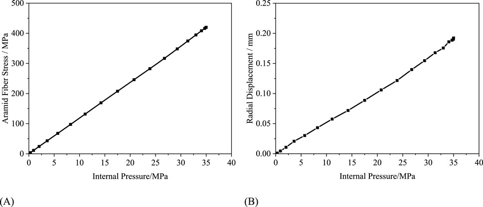
Figure 9. The mechanical response results of internal pressure reinforced layer under 35 MPa internal pressure: (A) Stress-load curve. (B) Radial displacement-load curve.
4.1.2 External pressure load
The distribution of stress in the flexible pipe under an external pressure of 15 MPa is depicted in Figure 10. The external pressure reinforcement layer mainly bears the external pressure. This is because the tensile reinforcement layer on the external side is made of aramid fiber bundles, which cannot withstand external pressure. Additionally, the antiwear layer and outer sheath layer are made of thermoplastic materials with lower mod-ulus, limiting their radial load-bearing capacity. Therefore, the external pressure mainly acts on the external pressure reinforcement layer. The maximum stress in the external pressure reinforcement layer under the 15 MPa external pressure load is calculated as 118.1 MPa, and the material still remains elastic.
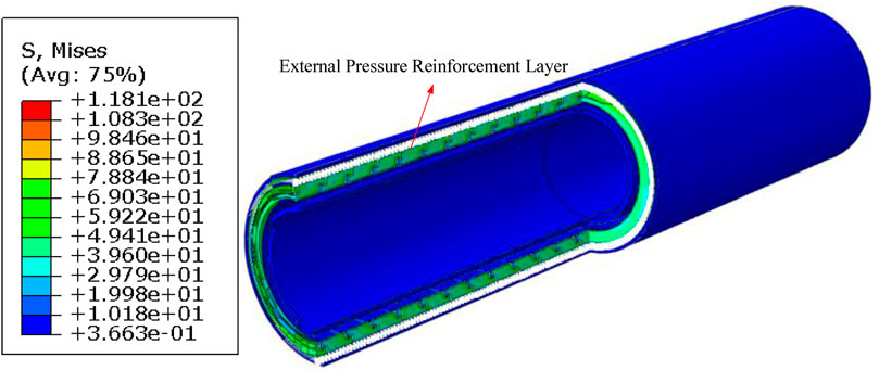
Figure 10. Stress distribution of flexible pipe under 15 MPa external pressure.
The local stress distribution of the outer pressure reinforcement layer is shown in Figure 11. It can be observed that under the external pressure, the stress distribution in the external pressure reinforcement layer is relatively uniform. The maximum stress occurs at the front tooth-like structure of the spiral band. This is because under the external pressure load, the external pressure reinforcement layer undergoes radial deformation, and its tooth-like structure contacts with the lower end spiral band, resulting in some stress con-centration at this point. The stress in the main part of the external pressure reinforcement layer is around 70 MPa.
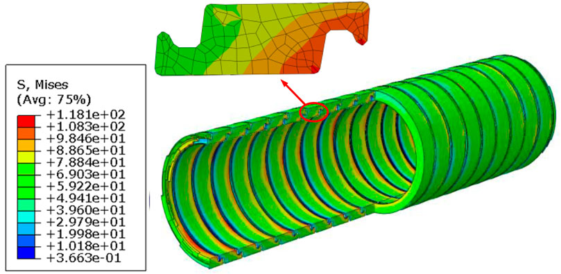
Figure 11. Stress of external pressure reinforced layer under 15 MPa external pressure.
As shown in Figure 12A, the variation of the maximum stress in the external pressure reinforcement layer with increasing external pressure load is depicted. It can be observed that under the external pressure, the stress in the external pressure reinforcement layer exhibits a linear relationship with the external pressure, with the stress increasing with the increase in external pressure. Under the action of external pressure, flexible pipe will experience radial displacement towards the center of the pipe. The radial displacement-external pressure load curve of the outer pressure reinforcement layer can effectively represent the radial bearing capacity of the flexible pipe, as shown in Figure 12B. It can be observed that the radial deformation of the external pressure reinforcement layer exhibits a nearly linear growth trend with the increase in external pressure, with an approximate ratio of external pressure to radial displacement of 20.7 MPa/mm. The trend of radial dis-placement between external pressure loads of 6 MPa and 12 MPa shows slight variations, possibly due to the influence of frictional contact between the spiral bands of the external pressure reinforcement layer on the radial deformation of the pipe.
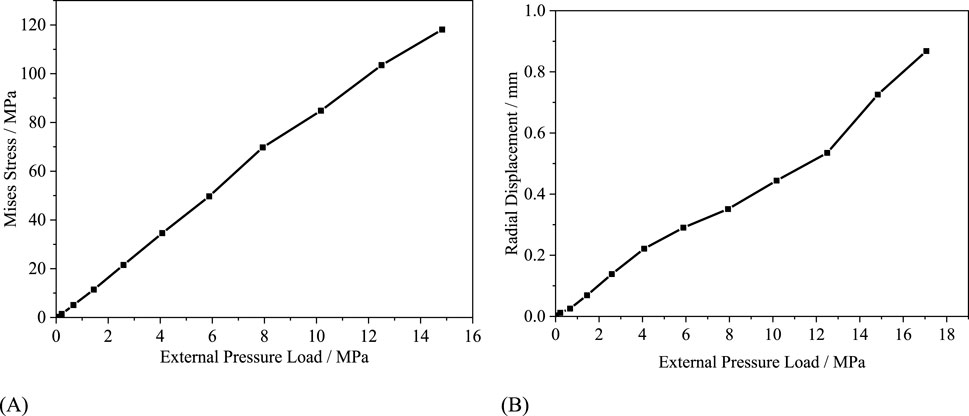
Figure 12. The mechanical response results of external pressure reinforced layer under 15 MPa external pressure: (A) Stress-load curve. (B) Radial displacement-load curve.
4.1.3 Axial tensile load
The stress plots of the flexible pipe under axial tensile load of 1,200 kN obtained through finite element modeling is shown in Figure 13A. It can be seen that under the axial tensile load, the maximum stress of 202.9 MPa is in the tensile reinforcement layer of the flexible pipe, indicating that the tensile reinforcement layer plays a primary role in axial load bearing. This is because the tensile reinforcement layer has a greater axial stiffness compared to other functional layers. The weave angle of the internal pressure reinforcement layer with respect to the axial direction of the pipe is 55°, primarily providing radial load-bearing capacity.
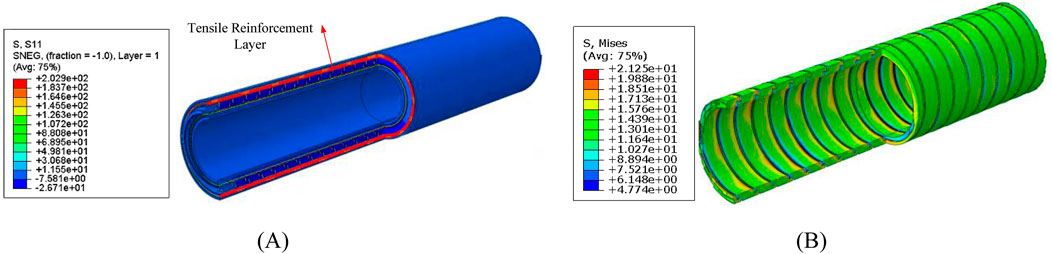
Figure 13. Stress of flexible pipe and external pressure reinforced layer under 1200 kN tensile load: (A) Stress of flexible pipe under 1200 kN tensile load. (B) Stress of external pressure reinforced layer.
The external pressure reinforcement layer is composed of S-shaped cross-section carbon fiber reinforced composite strips wound in a large angle spiral, with certain gaps between the spiral strips. Under axial tensile load, sliding can occur between the spiral strips, resulting in very low axial tensile stiffness of the outer pressure reinforcement layer, almost no axial load-bearing capacity is provided by the external pressure reinforcement layer. The stress in the external pressure reinforcement layer under tensile load is shown in Figure 13B, with the maximum stress value of only 21.3 MPa.
The variation of stress in the tensile reinforcement layer fiber bundle under axial tensile load is shown in Figure 14A. It can be observed that the stress in the aramid fiber bundle of the tensile reinforcement layer under axial tensile load exhibits a linear relationship with the axial tensile load. This curve can be used for stress assessment and calculation of the tensile reinforcement layer under axial tensile load, providing a basis for the design and manufacture of the tensile reinforcement layer of flexible pipes. By extracting the elongation of the pipe under tensile load, the axial tensile stiffness of the flexible pipe can be obtained, as shown in Figure 14B. Under axial tensile load, the axial strain of the flexible piper is linearly related to the tensile load, with the tensile load increasing with the in-crease in axial strain. This is because in this study, the flexible material is considered to be elastic, but due to the nonlinear contact and friction between the functional layers, the curve of tensile force and elongation strain fluctuates. The axial tensile stiffness of the flexible pipe is calculated as 413.0 MN based on the slope of the curve.
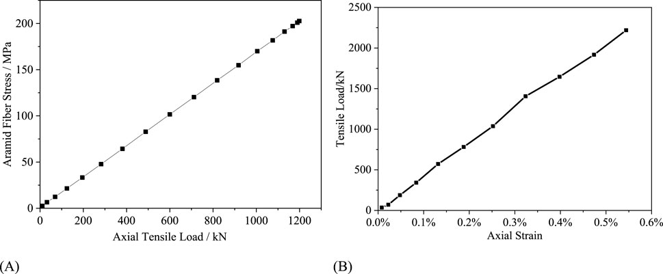
Figure 14. The mechanical response results of tensile reinforcement layer under 1200 kN tensile load: (A) The curve of fiber bundle stress. (B) Elongation-tensile load curve.
4.1.4 Bending load
At RP-1 and RP-2, angular deviations of 0.25 radians are applied around the central axis of the pipe. The deformation of the flexible pipe under bending load is shown in Figure 15A. It can be observed that under the bending load, the flexible pipe undergoes upward arching deformation, with deformation uniformly coordinated across various functional layers. Under a curvature of 0.25 m−1, the maximum displacement of the flexible pipe is 72 mm.
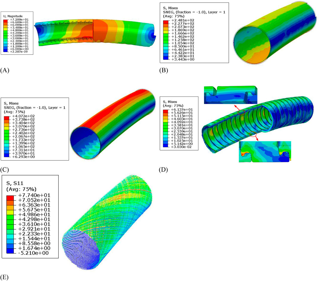
Figure 15. Contour plot distribution of flexible pipe under bending load: (A) Deformation of flexible pipe under bending load. (B) Internal pressure reinforcement layer 1. (C) Internal pressure reinforcement layer 1. (D) External pressure reinforcement layer 1. (E) Tensile reinforcement layer.
The stress distributions across functional layers of the flexible pipe under a curvature of 0.25 m−1 are presented in Figures 15B–E. It can be observed that under the bending load, the maximum stress is in the second internal pressure reinforcement layer of the flexible pipe, reaching 407.2 MPa. This is attributed to the fact that under the same deformation curvature, the second outer internal pressure reinforcement layer experiences greater bending strain compared to the first outer internal pressure reinforcement layer. Additionally, since the internal pressure reinforcement layer is composed by densely woven aramid fibers, it cannot recede the bending induced tensile/compressive stress by slipping among fiber bundles, hence leading to a greater local stress value.
The stress distribution of the fiber bundles in the tensile reinforcement layer is analyzed separately. Since the aramid fiber bundles are wounded in 30° angle, when the axial force on the tensile reinforcement layer exceeds the frictional force induced by interlayer pressure, sliding happens among the aramid fiber bundles. This leads to changes in the mechanical properties of the tensile reinforcement layer, affecting its bending stiffness. The bending moment data at reference point RP-2 and the stress of aramid fiber bundles are extracted and plotted in Figure 16. The bending moment curve can be divided into three segments. Firstly, when the bending curvature is small, the bending moment of the tensile reinforcement layer increases linearly with curvature. At this stage, the bending stiffness of the tensile reinforcement layer is constant, at 387.9 kN·m2. When the bending moment of the tensile reinforcement layer increases to the critical slip moment of 0.116 m−1, the trend of the bending moment changes to nonlinear growth with curvature. As the curvature increases, the bending stiffness of the tensile reinforcement layer decreases. At this point, aramid fiber bundles undergo slipping behavior, leading to reduced load-bearing capacity. The average bending stiffness during the slip segment is 138.93 kN·m2. When the bending curvature of the pipe increases to 0.249 m−1, the aramid fiber bundles reach equilibrium and stop slipping. At this point, the trend of bending moment against curvature at the end returns to approximately linear, and the average bending stiffness of the tensile reinforcement layer after slipping stage is 288.9 kN·m2. When the aramid fiber bundles change their slipping state at curvatures of 0.116 m−1 and 0.249 m−1 respectively, the stress on the fiber bundles also changes accordingly. The stress increment of the aramid fiber bundles is relatively small in the pre-slip stage. When the aramid fiber bundles enter the slipping stage, their mechanical state is influenced by the slipping behavior, causing an increase in stress level of the fiber bundles with increasing bending moment. After the aramid fiber bundles cease slipping behavior, the amplitude of stress variation changes again. In all three stages, the stress increases linearly along with the increase of bending curvature. Moreover, it is noteworthy that the critical slip curvature observed in this study (0.116 m−1) is significantly higher than that reported for metallic pipes by Witz (0.05–0.1 m−1). This discrepancy may be attributed to the relatively lower friction coefficient characteristic of non-metallic layers, which facilitates more pronounced interlayer slip behavior (Witz, 1996).

Figure 16. Bending moment and stress of tensile layer under bending load.
The bending stiffness is a key structural parameter of the flexible pipe. Figure 17 illustrates the correlation between the bending moment at reference point RP-1 and curvature of the flexible pipe. It compares the bending moment-curvature data of the tensile reinforcement layer with that of the entire flexible pipe. It can be observed that the flexible pipe exhibits slipping behavior under bending load, and the bending stiffness variation trend in the flexible pipe across the three stages is generally similar to that of the tensile reinforcement layer. The critical slip curvature of the aramid fiber bundles in the entire flexible pipe model is also consistent with that of the tensile reinforcement layer. The critical slip curvature of the tensile reinforcement layer and the nonmetallic flexible pipe is larger compared to that of the metallic flexible pipe, which typically ranges from 0.05 to 0.1 for an equivalent size.
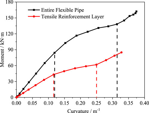
Figure 17. Bending stiffness comparison between flexible pipe and tensile reinforced layer.
The linear stress-displacement relationships in Figures 9, 12, 14 validate the numerical model’s accuracy under monotonic loading, consistent with the elastic behavior of aramid and carbon fiber composites.
4.2 Combined loads
Combined loads included axial tension + internal pressure, axial tension + external pressure, and bending + internal/external pressure, mimicking deepwater operations.
4.2.1 The effect of combined loads on the axial stiffness of flexible pipes
The study considers combined loads including axial, bending, and internal pressure. These load types were chosen to replicate real-world operating conditions of non-metallic flexible pipes, where multiple forces typically act simultaneously. To investigate the deformation behavior of the flexible pipe under combined loading conditions (internal pressure, external pressure, and axial tension), in the first load step, an internal pressure of 35 MPa or an external pressure of 15 MPa was applied to the pipe. In the second load analysis step, an axial tensile load of 1,600 kN is applied. The tensile load-axial strain curve for the flexible pipe under the action of internal pressure and external pressure is shown in Figure 18. It can be seen that the tensile load of the flexible pipe under the action of internal pressure and external pressure increases linearly with axial strain, and the influence of internal pressure on the axial tensile stiffness of the flexible pipe is greater than that of external pressure. This is because the internal pressure, while increasing the interlayer pressure, also causes radial expansion deformation between the internal pressure reinforcement layer and the tensile reinforcement layer, which can resist a certain axial tensile load, thereby increasing the axial tensile stiffness of the flexible pipe. Under the action of external pressure, the inter-layer frictional force between various functional layers increases, thereby increasing the stiffness of the flexible pipe during axial deformation.
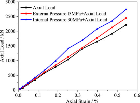
Figure 18. Tensile stiffness of non-metallic flexible tube under combined load.
The axial tensile stiffness of the flexible pipe under different internal pressure and external pressure loads are calculated separately, as shown in Figures 19A,B. It can be observed that both internal pressure and external pressure loads increase the axial tensile stiffness of the tensile reinforcement layer, with the magnitude of increase growing larger with the increase in pressure load. Under an internal pressure of 35 MPa, the axial tensile stiffness of the flexible pipe is 504.4 MN, representing a 22.1% increase compared to the case of a single tensile load. Under an external pressure of 35 MPa, the axial tensile stiffness of the flexible pipe is 449.7 MN, with an increase of 8.9%. Therefore, in actual operating conditions, the axial tensile load of the flexible pipe will increase due to the effects of internal pressure and external pressure. When conducting a whole-pipe analysis of the flexible pipe, the axial tensile stiffness considering the effects of internal pressure and ex-ternal pressure should be used as an input parameter.
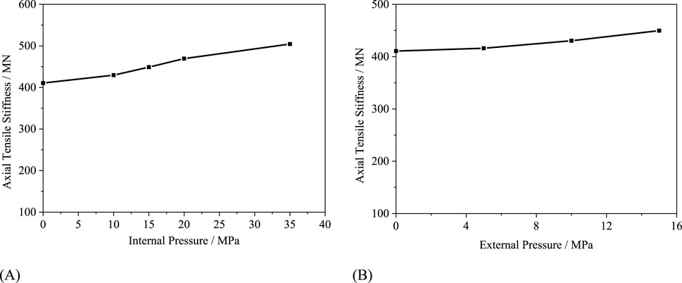
Figure 19. Axial stiffness of flexible pipe: (A) Internal pressure. (B) External pressure.
4.2.2 The influence of combined loads on the bending characteristics of flexible pipes
In the first load step, different concentrated forces are applied at reference point RP-1. In the second load step, angular deviations of 0.3 radians are respectively applied around the central axis of the pipe at reference points RP-1 and RP-2. The bending moments of the flexible pipe under combined axial tensile load and bending load are extracted, as shown in Figure 20A. It can be observed that the bending stiffness of the flexible pipe increases un-der the combined axial tensile load. Additionally, when the axial tensile load reaches 1,200 kN, the trend of bending stiffness variation of the flexible pipe changes, with less pronounced slipping behavior. The critical slip curvature of the flexible pipe increases with the increase of axial tensile load. Moreover, as the axial tensile load increases, the magnitude of increase in bending stiffness of the flexible pipe also rises.
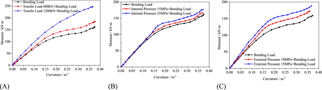
Figure 20. Bending stiffness variation of flexible pipe under different loads: (A) Axial tensile load and bending load. (B) Internal pressure and bending load. (C) External pressure and bending load.
The bending stiffness variation of the flexible pipe under combined internal pressure load and bending load is shown in Figure 20B. The effect of internal pressure load on the bending stiffness of the non-slipping segment of the flexible pipe is minimal. However, as the internal pressure load increases, the critical slip curvature of the flexible pipe increases. This is because the action of internal pressure load increases the interlayer pressure be-tween various functional layers, thereby increasing the frictional force during the bending deformation of the tensile fiber bundles, requiring a larger bending deformation to reach the slipping stage. The bending stiffness after slipping simultaneously increases with the increase of internal pressure. The bending stiffness of the flexible pipe under combined external pressure load and bending load is shown in Figure 20C. The action of external pressure load increases the bending stiffness of the non-slipping and slipping segments of the flexible pipe, and the critical slip curvature of the tensile reinforcement layer gradually increases with the increase of external pressure load. This phenomenon occurs because the material layers undergo compression under external pressure loading, causing more pronounced interaction between functional layers. The increased interlayer friction during fiber bundle bending deformation consequently leads to higher structural bending stiffness. In summary, internal pressure increases interlayer contact pressure, enhancing frictional resistance to axial deformation, while external pressure compresses layers, reducing relative slip and increasing bending stiffness. These mechanisms are directly linked to the composite materials’ high specific strength and nonlinear contact behavior.
5 Results
In this paper, a three-dimensional finite element model of flexible pipe which con-siders the real structural and material parameters is established to analysis the mechanical behavior of flexible pipe under different loads. The model is validated by comparing with the full-scale internal pressure bursting experimental results. Then, the model is further employed to study the effects of different loads on the mechanical behavior of flexible pipe. The main findings are summarized as follows:
(1) The elongation strain of the flexible pipe increases almost linearly with increasing tensile force during the loading process, with a tensile stiffness of 413.0 MN under pure tensile load. Compared with the pure tensile load condition, combined loads significantly affect the tensile stiffness of the flexible pipe. Both internal and external pressures cause tighter fitting between layers, thereby increasing the tensile stiffness. At an internal pressure of 35 MPa, the tensile stiffness reaches 504.4 MN, representing a 22.1% increase compared to the pressure-free case. Similarly, under an external pressure of 15 MPa, the tensile stiffness measures 449.7 MN, showing an 8.9% increase relative to the pressure-free condition.
(2) Under pure bending loading conditions, the bending stiffness of the flexible pipe exhibits nonlinear behavior due to internal slippage within the tensile armor layer. When subjected to combined axial tension and bending loads, the flexible pipe demonstrates increased bending stiffness. This stiffening effect becomes particularly evident when the axial tensile load exceeds 1,200 kN, at which point the interlayer slippage behavior is significantly reduced.
(3) The internal pressure exhibits minimal influence on the bending stiffness of the non-slipping segment in flexible pipes. Both the critical slip curvature and post-slip bending stiffness increase with rising internal pressure. In contrast, increasing external pressure enhances the bending stiffness for both non-slipping and slipping segments, while also elevating the critical slip curvature of the pipe.
(4) The findings suggest that internal and external pressures, as well as tensile and bending loads, significantly influence the stiffness and overall mechanical behavior of the pipes. By understanding these influences, manufacturers can select materials with appropriate mechanical properties, such as high tensile strength and elasticity, and optimize the layer thicknesses to ensure that the pipes can withstand the operational conditions without premature failure.
6 Equations
In the equation, IF is the failure criterion of the composite material; σ11, σ22, and τ12 are the stresses in the composite material; X, Y and S are the tensile strength and shear strength of the composite material, respectively.
Data availability statement
The raw data supporting the conclusions of this article will be made available by the authors, without undue reservation.
Author contributions
JY: Project administration, Writing – original draft. XY: Writing – original draft, Writing – review and editing. TK: Methodology, Writing – review and editing. MX: Investigation, Writing – review and editing. RL: Writing – review and editing. KZ: Data curation, Writing – review and editing. BW: Resources, Writing – review and editing.
Funding
The author(s) declare that financial support was received for the research and/or publication of this article. This research was funded by Key Science and Technology Project of Ministry of Emergency Management of the People’s Republic of China (Grant No. 2024EMST090903); National Key R&D Program of China (Grant No. 2022YFC3070100) and Young Elite Scientists Sponsorship Program by Beijing Association for Science and Technology (Grant No. BYESS2023261).
Acknowledgments
The authors would like to thank Key Science and Technology Project of Ministry of Emergency Management of the People’s Republic of China (Grant No. 2024EMST090903); National Key R&D Program of China (Grant No. 2022YFC3070100) and Young Elite Scientists Sponsorship Program by Beijing Association for Science and Technology (Grant No. BYESS2023261).
Conflict of interest
Authors JY, XY, MX, RL, and KZ were employed by CNOOC Gas and Power Group Ltd.
The remaining authors declare that the research was conducted in the absence of any commercial or financial relationships that could be construed as a potential conflict of interest.
Generative AI statement
The author(s) declare that no Generative AI was used in the creation of this manuscript.
Publisher’s note
All claims expressed in this article are solely those of the authors and do not necessarily represent those of their affiliated organizations, or those of the publisher, the editors and the reviewers. Any product that may be evaluated in this article, or claim that may be made by its manufacturer, is not guaranteed or endorsed by the publisher.
References
Avachat, S., and Zhou, M. (2016). High-speed digital imaging and computational modeling of hybrid metal-composite plates subjected to water-based impulsive loading. Exp. Mech. 56 (4), 545–567. doi:10.1007/s11340-015-0038-9
Clevelario, J., Pires, F., Falco, G., Tan, Z., and Lu, J. (2010). “Sheldrake, Flexible pipe curved collapse behavior assessment for ultra-Deepwater developments for the Brazilian pre-salt area,” in Proceedings of Offshore Technology Conference, Houston, TX, USA, 3–6 May, 2010.
Cornacchia, F., Liu, T., Bai, Y., and Fantuzzi, N. (2019). Tensile strength of the unbonded flexible pipes. Compos. Struct. 218, 142–151. doi:10.1016/j.compstruct.2019.03.028
Dai, T., Sævik, S., and Ye, N. (2017). Friction models for evaluating dynamic stresses in non-bonded flexible risers. Mar. Struct. 55, 137–161. doi:10.1016/j.marstruc.2017.05.010
De Sousa, J. R. M. (2001). “Local mechanical behavior of flexible pipes subjected to installation loads,” in Proceedings of the International Conference on Offshore Mechanics and Arctic Engineering, Rio de Janeiro, Brazil.
De Sousa, J. R. M., Magluta, C., Roitman, N., and Campello, G. C. (2018). On the extensional-torsional response of a flexible pipe with damaged tensile armor wires. Ocean. Eng. 161, 350–383. doi:10.1016/j.oceaneng.2018.04.091
Ebrahimi, A., Kenny, S., and Hussein, A. (2018). Finite element investigation on the tensile armor wire response of flexible pipe for axisymmetric loading conditions using an implicit solver. J. Offshore Mech. Arct. Eng. 140, 041402. doi:10.1115/1.4039132
Li, H., Chen, C., and Lu, C. (2025). Multiscale simulation method for anti-penetration of fiber-reinforced composite laminates. Chin. J. High Press. Phys., 1–12. doi:10.11858/gywlxb.20240940
Lukassen, T. V., Gunnarsson, E., Krenk, S., Glejbøl, K., Lyckegaard, A., and Berggreen, C. (2019). Tension-bending analysis of flexible pipe by a repeated unit cell finite element model. Mar. Struct. 64, 401–420. doi:10.1016/j.marstruc.2018.09.010
Qu, P. (2009). Analysis on mesoscopic mechanics of 2D biaxial braided composites. Jinan, Shandong, China: Shan Dong University.
Ren, S., Liu, W., Song, Y., Geng, H., and Wu, F. (2018). Crushing study for interlocked armor layers of unbonded flexible risers with a modified equivalent stiffness method. Int. J. Nav. Archit. Ocean Eng. 11, 521–529. doi:10.1016/j.ijnaoe.2018.09.006
Sævik, S., and Thorsen, M. J. (2012). “Techniques for predicting tensile armour buckling and fatigue in deep water flexible pipes,” in ASME International Conference on Ocean, Rio de Janeiro, Brazil, 1–6 July, 2012, 469–482. doi:10.1115/omae2012-83563
Venkadesh, R., Monssef, D., Laurent, G., and Khadhour, A. (2016). Numerical simulation analysis as a tool to identify areas of weakness in a turbine wind-blade and solutions for their reinforcement. Compos. Part B 103, 23–39. doi:10.1016/j.compositesb.2016.07.018
Wang, B., Xiao, B., Zhang, H., Liu, X., and Xu, L. (2021). A combined experimental and numerical simulation approach for burst pressure analysis of fiber-reinforced thermoplastic pipes. Ocean. Eng. 236, 109517. doi:10.1016/j.oceaneng.2021.109517
Wang, B. D., Zhang, H., and Liu, X. B. (2019). “Mechanical behaviors of reinforced thermoplastic pipe under combined load,” in Pressure Vessels and Piping Conference PVP2019, San Antonio, TX, USA, 14-19 July, 2019.
Witz, J. A. (1996). A case study in the cross-section analysis of flexible risers. Mar. Struct. 9 (9), 885–904. doi:10.1016/0951-8339(95)00035-6
Yang, X., Saevik, S., and Sun, L. (2015). Numerical analysis of buckling failure in flexible pipe tensile armor wires. Ocean. Eng. 108, 594–605. doi:10.1016/j.oceaneng.2015.08.011
Keywords: nonmetallic unbonded flexible pipe, mechanical behaviors, nonlinearity finite element, loads, simulation analysis
Citation: Yu J, You X, Kong T, Xia M, Lv R, Zhang K and Wang B (2025) Analysis of the mechanical behaviors of nonmetallic un-bonded flexible pipe under different loads. Front. Mater. 12:1560428. doi: 10.3389/fmats.2025.1560428
Received: 14 January 2025; Accepted: 30 June 2025;
Published: 18 July 2025.
Edited by:
Qingzhen Yang, Xi’an Jiaotong University, ChinaReviewed by:
Monssef Drissi Habti, Université Gustave Eiffel, FranceVaibhav S. Kathavate, MIT World Peace University, India
Copyright © 2025 Yu, You, Kong, Xia, Lv, Zhang and Wang. This is an open-access article distributed under the terms of the Creative Commons Attribution License (CC BY). The use, distribution or reproduction in other forums is permitted, provided the original author(s) and the copyright owner(s) are credited and that the original publication in this journal is cited, in accordance with accepted academic practice. No use, distribution or reproduction is permitted which does not comply with these terms.
*Correspondence: Tianwei Kong, a3R3OTgxMTE2QDE2My5jb20=