 Zeyu Zuo1,2
 Zhenhua Yu3,4Qingle Hou5Kai Ren1,2Jie Zhang1*Chengjun Zhang5
 Ruiyong Zhang1*
 Wolfgang Sand6Zhao Hu1
 Xilei Chen2
 Jizhou Duan1Baorong Hou1
- 1Key Laboratory of Advanced Marine Materials, Institute of Oceanology, Chinese Academy of Sciences, Qingdao, China
- 2College of Environment and Safety Engineering, Qingdao University of Science and Technology, Qingdao, China
- 3Qingdao Municipal Center for Disease Control and Prevention, Qingdao, China
- 4Qingdao Institute of Preventive Medicine, Qingdao, China
- 5Wanhua Chemical Group Co., Yantai, China
- 6Institute of Biosciences, University of Mining and Technology, Freiberg, Germany
Cooling water heat exchangers are essential components in chemical production processes, requiring long-term stability under corrosive circulating cooling water conditions. Coating protection technology has become increasingly widespread for mitigating corrosion in these systems. However, prolonged immersion in cooling water during operation can result in coating degradation and detachment. This study examines the corrosion behavior associated with coating damage in cooling water heat exchangers under varying immersion times. Coated carbon steel specimens were coupled with artificially stripped specimens to simulate large cathode and small anode systems in a cooling water environment. The results reveal that the corrosion rate of the small exposed anode increases as the exposure area decreases. Simultaneously, the adhesion between the coating and the substrate of the large cathode weakens with immersion time, leading to the formation of voids regardless of the exposure area. The findings indicate that in practical applications, smaller areas of coating delamination drive localized corrosion at the exposed substrate, whereas larger areas promote internal corrosion beneath the coating, ultimately leading to complete coating failure.
1 Introduction
In chemical production processes, heat exchangers play a critical role but often operate in harsh environments. These demanding conditions make heat exchangers particularly susceptible to issues such as corrosion thinning, erosion corrosion, fatigue fracture, and stress corrosion cracking. As a result, they are among the components most prone to failure in such systems (Faes et al., 2019; Ali et al., 2021; Kuźnicka, 2009; Sharma and Roy, 2015).
In order to effectively mitigate corrosion induced by environmental conditions and to prevent heat exchanger failure—potentially resulting in economic losses or safety hazards—protective coatings are increasingly employed on carbon steel heat exchangers to reduce and delay corrosion processes (Bhuvanendran Nair Jayakumari et al., 2023; Fedrizzi et al., 2008; Liu et al., 2024; Kazi, 2020; Zhang et al., 2022). The application of anticorrosion coatings provides an effective barrier between the external environment and the metal substrate of the heat exchanger, thereby delaying corrosion caused by environmental exposure and prolonging the operational lifespan of the equipment. However, prolonged immersion in cooling water environments can compromise the lifespan and anti-corrosion efficiency of these coatings. Under conditions of cooling water flow and high-temperature immersion, localized coating damage may occur (Kuźnicka, 2009), exposing the underlying substrate to the high-temperature cooling water. In such cases, the exposed metal substrate acts as an anode while the coated areas serve as a cathode, forming a large cathode-to-anode ratio and triggering galvanic coupling corrosion (Mousavian et al., 2011; Yang et al., 2012). This process accelerates the corrosion at the damaged areas, increasing the risk of failure in cooling water pipelines and threatening the safety of chemical production systems.
This study investigates the issue of corrosion in heat exchangers following coating damage by evaluating the changes in corrosion behavior and rates of carbon steel specimens at damaged coating sites. By designing different coating damage areas and immersion times, the research aims to analyze the accelerated corrosion of heat exchanger tube bundles caused by localized coating damage. The findings are expected to serve as a valuable reference for the design, operation, and maintenance of chemical production units, enhancing decision-making and improving system reliability.
2 Materials and methods
The coating used in this experiment is a specialized organic anticorrosive coating designed for heat exchange equipment, applied in four layers to achieve a total thickness of no less than 120 μm. The test specimens were made of 20# steel, and to enhance adhesion between the steel substrate and the coating, the specimens were sandblasted prior to coating application. The experimental setup is illustrated in Figure 1. For the large cathode, a fully coated 20# steel specimen with dimensions of 2 × 5 × 0.5 cm was used, leaving a working surface area of 10 cm2 while the remaining surface was sealed with epoxy resin. The small anodes consisted of two types of specimens: one with 30% exposed surface area (dimensions: 2 × 1.5 × 0.5 cm, working surface: 3 cm2) and another with 60% exposed surface area (dimensions: 2 × 3 × 0.5 cm, working surface: 6 cm2). Both types of small anodes were bare steel with the remaining surfaces sealed with epoxy resin. The large cathode and the corresponding small anodes were paired to form coupling pairs with 30% and 60% exposed areas, respectively, and connected using wires. The coupled pair was immersed in a chemical cooling water environment, with the main components and properties of the cooling water listed in Table 1. A constant-temperature water bath was used to heat the solution to 50°C, and the immersion was maintained continuously for 40 days.
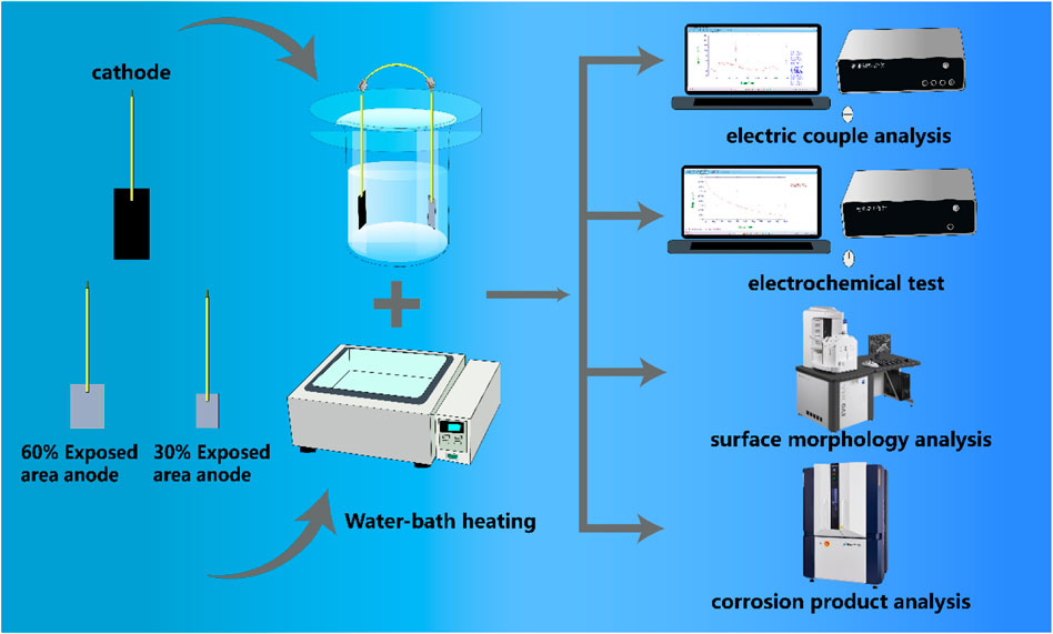
Figure 1. Experimental setup and flow chart.

Table 1. Main components and properties of cooling water.
2.1 Weight loss tests
The weight loss tests were conducted on the small anodes with different exposed areas in the coupling pairs on the 4th, 16th, 30th, and 40th days of immersion. Three parallel samples were used at each time point to ensure the repeatability of the experiment. A pickling solution was used to remove the corrosion products from the surface of the small anodes. The samples were then sequentially washed with distilled water and absolute ethanol, followed by drying with high-purity N2. Based on the weight loss of the samples, the corrosion rate of the small anode (Vcorr, mm/a) was calculated using Equation 1.
where Δm is the weight difference of the sample before and after immersion, ρ is the density of the sample (g/cm3), A is the exposed surface area of the sample (cm2), and t is the immersion time (h).
2.2 Galvanic current measurement
The galvanic current measurement method is widely employed in the evaluation of corrosion inhibitors, cathodic protection systems, and studies on galvanic corrosion in metal couples (Zhang et al., 2023; Nakagawa et al., 2010; Chen et al., 2023). The galvanic coupling current measurement method is primarily used to study the galvanic corrosion characteristics of metal coupling pairs in electrolyte solutions from a kinetic perspective. Currently, the most commonly employed measurement techniques include the zero-resistance ammeter (ZRA) method and the constant potential meter method (Okonkwo et al., 2021; Wang et al., 2018; Yang and Yang, 2017; Curioni et al., 2013). In this study, the CHI1030C potentiostat was used for measurements. Figure 2 illustrates the working principle of the potentiostat.
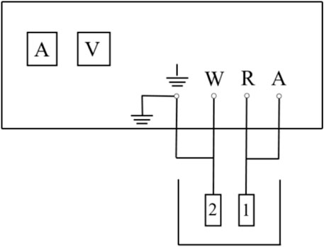
Figure 2. Schematic diagram of potentiostat measurement.
2.3 Galvanic potential measurement
Galvanic potential measurement is a crucial step in evaluating the potential difference formed when a metal substrate establishes a galvanic pair in an electrolyte solution (Chen et al., 2023). The galvanic potential clearly reflects the corrosion tendency of a metal when forming a galvanic pair. Additionally, the higher the galvanic potential, the greater the risk of galvanic corrosion (Li et al., 2024; Omar Rihan, 2014). This means that more intense electrochemical reactions will lead to more severe corrosion. In this report, the galvanic potential is measured using a potentiostat. The working surfaces of the anode and cathode are positioned opposite each other, with a 5 cm distance between them, and are fully immersed in a cooling water solution. The anode and cathode are coupled using wires, and a saturated calomel electrode is used as the reference electrode.
2.4 Electrochemical impedance spectroscopy
Electrochemical Impedance Spectroscopy (EIS) was performed using a CHI660 electrochemical workstation, with separate tests conducted on the cathode and anode specimens. A three-electrode system was used, with the cathode or anode as the working electrode, a saturated calomel electrode as the reference electrode, and a platinum electrode as the counter electrode. The tests were conducted in a cooling water medium at the corresponding temperature. Prior to testing, the specimens were immersed in the medium at the designated temperature for 30 min to stabilize the system. Electrochemical impedance spectroscopy measurements were carried out under open circuit potential (OCP) conditions, with a 10 mV sine wave as the amplitude of the alternating current voltage and a scan frequency range from 10–2 Hz to 10–5 Hz. The test results were fitted and analyzed using Zsimp Win Version 3.21 software.
2.5 Surface morphology analysis
After the immersion test, the coupled parts of the samples were separated. The small anode working surface was then acid-washed using a corrosion product acid solution, followed by rinsing with deionized water to remove any residual acid solution. The samples were quickly dried using nitrogen gas and subsequently analyzed using Scanning Electron Microscopy (SEM) for surface morphology observation.
2.6 Corrosion product analysis
After the immersion experiment, the samples were collected, and the galvanic couples were separated. The small anode was removed, and the corrosion products formed on its surface were scraped off and collected. Simultaneously, the corrosion products suspended in the corresponding cooling water were centrifuged, and the upper clear liquid was removed. The collected corrosion products were then mixed with those from the small anode. The mixture was dried in a vacuum oven, and once completely dried, X-ray diffraction (XRD) testing was performed on the samples.
3 Results and discussion
3.1 Macroscopic corrosion morphology analysis
Figure 3 shows the macroscopic corrosion morphology of the small anode in the large cathode-small anode system after 40 days of immersion in a 50°C cooling water environment. From the figure, it can be observed that the small anode with 30% exposed area has more corrosion products than the one with 60% exposed area. This is due to the larger current density caused by the smaller exposed area, which accelerates the corrosion process. For the small anode with 30% exposed area, corrosion products were abundant but not dense during the first 16 days, and they did not completely cover the entire working surface. Between days 16 and 22, the corrosion products began to accumulate and gradually covered the working surface. From days 22–40, the corrosion products completely covered the working surface and started to accumulate. For the small anode with 60% exposed area, corrosion products began to cover the working surface gradually from days 1–16. From days 16–40, the corrosion products fully covered the working surface; however, they were not as dense as those on the 30% exposed area small anode.
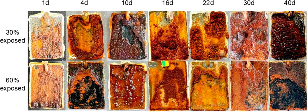
Figure 3. Macroscopic corrosion morphology of small anode in large cathode-small anode system after 40 Days of immersion in 50°C cooling water environment.
By comparing the changes in macroscopic morphology for different exposed areas, it can be observed that specimens with smaller exposed areas have more corrosion products on their surface. This indicates that smaller exposed areas result in more severe corrosion, suggesting that the corrosion rate is inversely proportional to the exposed area (Feliu et al., 2017; Li et al., 2017). This may be attributed to the smaller exposed area resulting in a higher current density, which in turn intensifies the corrosion process.
3.2 Weight loss test
The weight loss test can be used to determine the corrosion development of anode metals with different exposed areas at various stages in a 50°C cooling water environment by calculating the corrosion rate, as shown in Figure 4. The corrosion rates of both anodes with different exposure areas exhibit a trend of initially decreasing and then increasing over time. Additionally, the corrosion rate of the 30% exposed area anode is higher than that of the 60% exposed area anode. Specifically, for the anode with a 30% exposed area, the corrosion rate is relatively high on the 4th day of immersion. At this stage, the oxide film on the anode surface disappears, increasing the electrochemical activity of the anode metal. Meanwhile, the large cathode is not yet under corrosion threat, and corrosion mainly occurs on the anode surface. As the immersion time increases, the corrosion rate of the anode significantly decreases on the 16th day. This is due to the dense accumulation of corrosion products forming a protective film on the anode metal surface, providing a certain degree of corrosion inhibition. By the 30th day, the accumulation of corrosion products reaches its peak. However, as immersion in high-temperature cooling water continues, the corrosion product film is gradually penetrated, weakening its inhibition effect and eventually leading to its failure. This results in a renewed increase in the electrochemical activity of the anode surface, causing the corrosion rate to rise again. For the anode with a 60% exposed area, the initial stage of immersion also shows a relatively high corrosion rate due to the disappearance of the oxide film. However, because of the larger exposed area, the generated galvanic current density is lower, making the corrosion less severe compared to the 30% exposed area anode. During immersion in cooling water, corrosion products begin to accumulate densely by the 16th day, reducing the electrochemical activity of the metal surface. At the same time, gaps start to appear in the cathodic coating, leading to a reduction in the anode corrosion rate. Due to the larger exposed area, the coverage of the corrosion product film occurs more slowly. From the 16th to the 40th day, the anode surface is gradually covered by the corrosion product film. During this period, corrosion products begin to appear in the gaps of the cathodic coating, driving further anode metal corrosion. However, the presence of the corrosion product film causes the corrosion rate to increase at a slower pace.
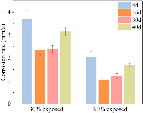
Figure 4. Anodic corrosion rates for different exposed areas in a 50°C cooling water environment.
3.3 Galvanic current density analysis
Galvanic current and galvanic current density can reflect the severity of galvanic corrosion, its variation over time, the optimal selection of galvanic pairs, and the effectiveness of protective measures (Wang et al., 2019). Additionally, they can be used to analyze the relationship between the galvanic current and the corrosion rate of the anode in the galvanic pair through calculation.
Figure 5 illustrate the current-time curves for the large cathode-small anode coupling system immersed in a 50°C cooling water environment for 40 days. It can be observed that regardless of the exposure area ratio of the small anode in the coupling system, the galvanic current exhibits a trend of initially increasing and then decreasing over time. This phenomenon occurs because, as the immersion time in the cooling water increases, small defects on the coating surface begin to expose, allowing the solution to penetrate through the coating and come into contact with the metal substrate, leading to an increase in galvanic current. With further immersion, corrosion products gradually accumulate on the metal surface, forming a corrosion product film that provides some protection to the metal substrate, thereby causing the current to decrease. For the coupling system with a 30% exposed area, the galvanic current increases during the first 1–16 days, then begins to decrease between days 16 and 30. Around day 30, a current reversal phenomenon occurs, and the current rises slightly again between days 30 and 40; For the coupling system with a 60% exposed area, the galvanic current increases during the first 1–4 days, decreases between days 4 and 16, and then rises again from days 16–40.
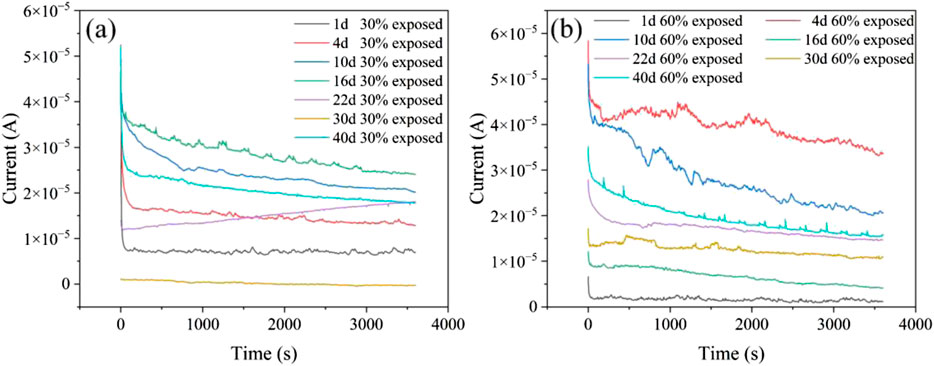
Figure 5. Current–time curves of coupled specimens with 30% and 60% exposed area at 50°C (a: 30% exposed area; b: 60% exposed area).
From the macroscopic morphology analysis, it can be observed that for the coupling system with a 30% exposed area, the accumulation of corrosion products during the first 16 days does not completely cover the entire working surface. At the initial stage of immersion, an oxide film forms on the metal surface, reducing surface activity, which explains why the galvanic current is initially low. As immersion time increases, the surface activity of the metal rises, and the oxide film is penetrated and destroyed, causing the galvanic current to increase. Simultaneously, corrosion products begin to accumulate densely on the surface. With the dense accumulation of corrosion products, the electron exchange between the metal and the solution becomes hindered, leading to a subsequent decrease in the galvanic current (Yoo et al., 2014). Although the corrosion product film can slow down the corrosion rate to a certain extent, leading to a decrease in galvanic current, its inhibition ability is limited (Chen et al., 2024). As immersion time increases, small defects in the cathode coating begin to emerge, allowing the solution to penetrate through the pores into the coating and form gaps between the coating and the metal substrate. This leads to an expansion of the exposed area, and the cathode substrate starts to corrode. The rate of decrease in galvanic current slows down. By the 30th day, the corrosion product film on the anode provides a certain shielding effect, while the failure of the cathode coating progresses further, enlarging the gaps under the coating. The contact area between the metal substrate and the solution increases, resulting in the phenomenon of current reversal on the 30th day. At this point, cathode corrosion intensifies, and the dense corrosion product film on the anode isolates electron exchange with the solution, causing the galvanic current to reverse. Subsequently, the inhibition capability of the corrosion product film in the cooling water environment weakens, and the shielding effect of the film begins to fail. This re-exposes the anode to the solution, leading to a rise in galvanic current. For the coupling system with a 60% exposed area, the macroscopic morphology analysis reveals that from the 1st to the 4th day, the corrosion products are not dense, and the cathode coating has not failed extensively. Consequently, as immersion progresses, the electrochemical activity on the anode surface increases, raising the galvanic current. With the dense accumulation of corrosion products, the corrosion product film begins to impede electron exchange between the anode surface and the solution, causing the galvanic current to decrease. Meanwhile, under the influence of high temperatures and cooling water, small defects in the cathode coating become exposed, weakening the adhesion between the cathode coating and the metal substrate, and gaps form. This allows the solution to contact the cathode substrate. Simultaneously, the corrosion product film on the anode is penetrated due to prolonged exposure to high-temperature cooling water, further expanding the anode’s working area. This results in an increase in galvanic current from the 30th to the 40th day. Due to the larger exposed area of the 60% coupling system’s anode, the corrosion products cannot completely cover the working surface. Thus, even with extensive cathode coating failure, no current reversal is observed in the system.
The galvanic corrosion sensitivity of a galvanic couple in an electrolyte solution is determined by the magnitude of the galvanic current density. The galvanic current can be used to calculate the galvanic current density, as shown in Figure 6. The average galvanic current is obtained using the integral method from the galvanic current-time curve. Then, the average galvanic current density is calculated based on the actual area of the anode in the galvanic couple (Dong et al., 2010). The calculation formula is shown in Equation 2:
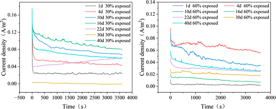
Figure 6. Couple current density curves of coupling pairs with different anode exposure areas in 50°C cooling water environment.
In the formula, Ig(t) represents the galvanic current at time t (A); S is the actual working area of the anode specimen (cm2); and t is the final time of the test (h).
The calculation results of the galvanic current ig for the large cathode and small anode galvanic couples at different corrosion times are shown in Table 2.
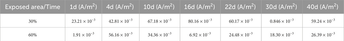
Table 2. Calculation of average coupling current density for large cathode and small anode coupling pairs.
Figure 7 shows the average galvanic current density of galvanic couples with different anode exposed areas in a 50°C cooling water environment. A comparison of the galvanic current density between the two coupling pairs with different anode exposed areas indicates that the coupling pair with 30% exposed area has a higher current density than the one with 60% exposed area. This suggests that the coupling pair with 30% exposed area has a more severe corrosion degree and a faster corrosion rate. This is because a smaller exposed area implies a smaller working surface, which concentrates the current. Additionally, more corrosion products accumulate on the anode of the 30% exposed area coupling pair, further reducing the effective working area. On the 30 days, the corrosion product film on the anode becomes densely accumulated, and with prolonged exposure to high-temperature cooling water, the adhesive force between the cathode coating and the metal substrate decreases. Cooling water infiltrates through small defects in the coating, forming gaps between the coating and the metal substrate, leading to contact between the cooling water and the metal substrate. As a result, the coating partially fails. With the accumulation of corrosion product film, the anode and cathode reverse, and the galvanic current crosses zero, resulting in a current reversal. Therefore, the galvanic current density at this point is relatively low.
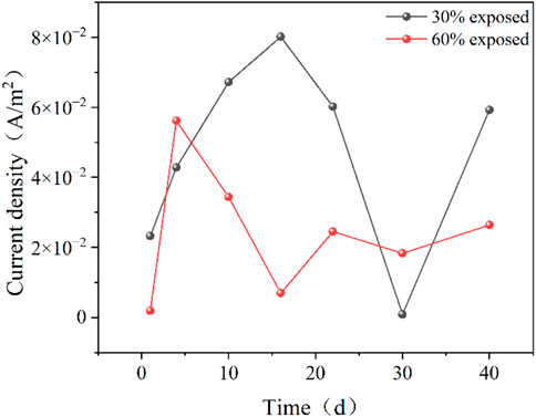
Figure 7. Average coupling current density for different anode exposure area coupling pairs in 50°C cooling water environment.
3.4 Galvanic potential measurement
As shown in Figure 8, the galvanic potentials of two galvanic couples with different anode exposure areas in a 50°C cooling water environment are presented. The average galvanic potentials of the two couples are calculated and shown in Figure 9. On the first day of immersion, the galvanic potentials of the couples with different anode exposure areas differ significantly, with the 30% exposure area couple having a higher galvanic potential than the 60% exposure area couple. This is due to more intense corrosion and electrochemical reactions on the metal surface in the early stages of immersion, and the initial electrochemical reactions may lead to interfacial reactions between the coating and the metal substrate, affecting the galvanic potential difference. As the immersion time increases, both couples exhibit a decrease in galvanic potential, which is attributed to the formation of an oxide film on the metal surface. The oxide film is eventually penetrated, and its corrosion inhibition ability weakens, leading to a subsequent increase in galvanic potential. As corrosion products accumulate and compact on the surface, the effective working area of the metal decreases, causing the galvanic potential to decline once more. After the corrosion product film fails and is penetrated, the galvanic potential increases again. From the figures, it can be observed that the galvanic potential of the 30% exposure area couple decreases more significantly. This indicates that compared to couples with larger exposed metal areas, the couple with smaller exposed areas is more easily covered by the corrosion product film, and the corrosion inhibition ability of the corrosion products is more pronounced (Shamsa et al., 2021). Additionally, a comparison of the two couples with different anode exposure areas reveals that although their galvanic potentials are not identical, the fluctuations are relatively small, suggesting that the dominant corrosion process in both cases is uniform corrosion.

Figure 8. Electrochemical potential of coupled metals with varying anode exposure areas during 40 days immersion in 50°C cooling water [(a): 30% anode exposure area; (b) 60% anode exposure area].
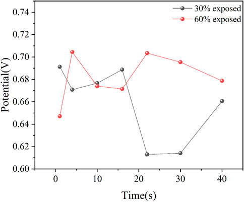
Figure 9. Pair of coupling potentials for different anode exposure area coupling in 50°C cooling water environment.
3.5 Electrochemical analysis
3.5.1 Open circuit potential
Open Circuit Potential (OCP) is a commonly used method in electrochemical testing (Hemkemeier et al., 2022; Choudhary et al., 2016; Michel et al., 2021), employed to measure the potential difference between the metal surface and the surrounding electrolyte in the absence of an applied external current. By analyzing the variations in OCP, insights can be gained into the coating failure and metal corrosion behavior.
As shown in Figure 10, the OCP of the large cathode and small anode in the 50°C cooling water environment is presented. From the figure, it can be observed that the OCP of the large cathode in both coupled systems with small anodes of different exposure areas first decreases and then increases. At the beginning of immersion, the OCP of the large cathode for both coupled systems is relatively positive, indicating that the coating provides effective protection to the metal substrate during the initial stage of immersion. From days 4–16, a rapid decline in OCP is observed, suggesting that the shielding effect of the coating gradually weakens. Small defects in the coating provide channels for the solution to contact the metal substrate, and with the increasing immersion time, gaps begin to appear between the coating and the metal substrate, thereby reducing the protective efficiency of the coating. On day 16, the OCP of the large cathode in both coupled systems becomes negative, indicating that significant corrosion of the metal substrate has occurred beneath the coating. The coating’s protective effect is diminished, and the exposed area of the anode is reduced due to the formation of the corrosion product film. This results in an increase in the anode activity of the cathode, leading to further corrosion. Between days 16 and 40, the corrosion product film formed on the metal substrate provides some passivation effect, causing the OCP to shift positively. However, during this period, the passivation effect of the corrosion product film on the anode surface weakens, and the exposed area begins to increase, which reduces the corrosion rate at the cathode.
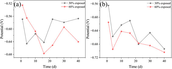
Figure 10. Open circuit potential variation of large cathode and small anode in coupled pairs with different exposure areas during 40 days of immersion in 50°C cooling water environment [(a): large cathode; (b) small anode].
The OCP of the small anode in the 50°C cooling water environment, which exhibits a trend of first decreasing, then increasing, and then decreasing again. The OCP trends for both small anodes with different exposure areas are consistent. On day 1, both systems show relatively positive OCP values, which is due to the formation of an oxide film on the metal surface at the beginning of immersion, reducing the surface’s electrochemical activity. From days 1–4, the OCP rapidly decreases due to the dissolution or breakdown of the oxide film. As corrosion products accumulate and form a dense corrosion product film, the electronic exchange at the metal surface is hindered, and the exposed anode area gradually decreases, leading to a quasi-passivation state. As a result, the OCP starts to rise, the exposed metal substrate of 30% exposure area is relatively smaller, so the accumulation of corrosion products becomes more compact, which leads to a slightly more positive OCP compared to the 60% exposure area anode. From days 16–40, the corrosion product film is gradually penetrated, causing the OCP to decrease again. Notably, on day 30, for the small anode with 30% exposure area, the compact accumulation of corrosion products again plays a significant role, resulting in a brief increase in OCP. This observation is consistent with the analysis of the galvanic current density.
By analyzing the OCP of both the cathode and anode in the galvanic pairs with different exposure areas, it can be observed that, regardless of the exposure area, the cathodic coatings of both systems have experienced failure. For the galvanic pair with a larger exposure area, the cathodic corrosion is relatively more severe. In contrast, the galvanic pair with a smaller exposure area, due to the smaller exposed metal substrate, has a relatively stronger corrosion inhibition effect from the corrosion products. This results in more localized corrosion on the cathode part (Wang et al., 2021; Zhou et al., 2024).
3.5.2 Electrochemical impedance spectroscopy
Electrochemical impedance spectroscopy (EIS) is a crucial tool for investigating metal corrosion rates and corrosion behaviors (Moradighadi et al., 2021; Zhong et al., 2008; Ribeiro and Abrantes, 2016), Additionally, for metals with coatings, EIS provides a more accurate assessment of the integrity of the metal coating and its protective effect on the metal in the solution.
In the cooling water medium, the metal substrate of the large cathode is coated with a layer of coating. As the high-temperature cooling water soaks the system, the adhesion between the metal and the coating weakens, leading to the formation of gaps between them. The solution enters these gaps and comes into contact with the metal substrate, generating corrosion products (Zhong et al., 2008). The corrosion products and the solution between the coating and metal become interwoven, making it difficult to distinguish between them. Based on the four key elements that influence electrochemical reactions at electrodes: the solution, coating, corrosion products in the coating gaps, and the charge transfer process at the double electric layer, an equivalent circuit, as shown in Figure 11, is used to fit the impedance spectra.
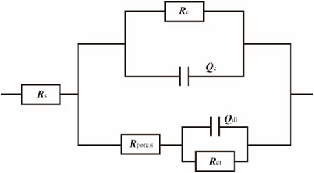
Figure 11. Fitted circuit of a coupled pair of large cathodes immersed in a cooling water environment at 50°C for 40 days.
In the equivalent circuit, Rs represents the solution resistance; Qc and Rc are the capacitance and resistance of the coating, respectively; Rpore.s is the resistance of the corrosion products in the gap between the coating and the metal substrate; Qdl is the double-layer capacitance; and Rct is the charge transfer resistance. The fitting results are presented in Tables 3, 4.
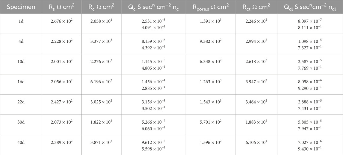
Table 3. Results of coupling to large cathode fitting for 30% exposed area in 50°C cooling water environment.
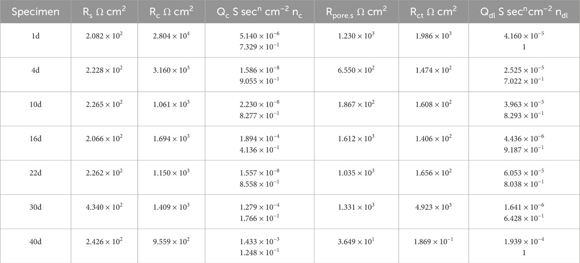
Table 4. Results of coupling to large cathode fitting for 60% exposed area in 50°C cooling water environment.
Figure 12 shows the EIS of the large cathode of coupled systems with different anode exposure areas after 40 days of immersion in a 50°C cooling water environment. At the beginning of the immersion, the Rct value of the coupled system with a 30% exposed area anode was smaller than that of the 60% exposed area anode. This indicates that, in the early stage of immersion, the larger exposed area of the small anode provides better protection for the cathode. As immersion progresses, from days 4–22, the Rct of the cathode with 30% exposed area gradually increases and surpasses that of the cathode with 60% exposed area. This is because, in the mid-term immersion, the smaller anode exposure area leads to a higher electrochemical current density, resulting in increased corrosion of the anode, which in turn provides corrosion inhibition for the cathode. At the same time, the bond between the coating and metal decreases, creating gaps in the coating where the solution can contact the metal substrate, generating a corrosion product film that plays a shielding role, which accounts for the gradual rise in Rct over time. At day 30, the anode of the 30% exposed area coupled system is fully covered by a dense corrosion product film. The accumulated corrosion products reach their peak, and the shielding effect of the corrosion product film on the anode exposure area is maximized. Meanwhile, gaps begin to appear under the cathode coating, allowing the metal substrate to contact the solution, causing a reversal of the cathode and anode. As a result, localized corrosion of the cathode intensifies, leading to a rapid decrease in the Rct of the cathode for the 30% exposed area system. In contrast, for the 60% exposed area coupled system, the corrosion product film is more widely spread but less dense, so the Rct of the 30% exposed area cathode becomes lower than that of the 60% exposed area cathode. By day 40, compared to the beginning of the immersion, the Rct of the cathode has decreased significantly, indicating the failure of the coating’s shielding effect. Large gaps have appeared between the coating and metal, allowing the solution to contact a large area of the cathode metal substrate. At this point, the Rct of the cathode with the 30% exposed area is again higher than that of the 60% exposed area system. This suggests that the corrosion product film on the smaller exposed area anode begins to lose its shielding effect, resulting in an increase in the anode surface electroactivity and resuming its corrosion inhibition effect. Based on the macroscopic corrosion morphology analysis, the larger exposed area anode surface may have formed a more dense corrosion product, weakening the corrosion inhibition effect, while localized cathodic corrosion intensified.
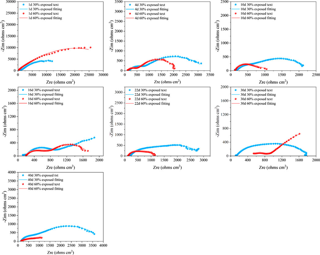
Figure 12. Electrochemical impedance spectra of large cathodes immersed for 40d in 50°C cooling water environment with different exposed area coupling pairs.
The analysis of the coating resistance (Rc) in the fitting results reveals that the Rc values of the cathodes with two different exposed areas decrease over the immersion period. This indicates that, as immersion time increases, the integrity of the coating deteriorates, and its shielding effect on the metal substrate is reduced. Comparing the Rc values of the two exposure areas, the trend of decline is consistent for both. From days 1–4, the coating resistance decreases rapidly, which may be attributed to the relatively high ion concentration in the cooling water solution during the early stages of immersion, leading to increased surface activity of the coating. As the immersion time progresses, the Rc decreases gradually. This is due to the disappearance of the anodic oxide film, an increase in surface electroactivity, and the formation of corrosion products. These corrosion products, suspended in the solution, attach to the cathode coating surface, acting as a shielding layer and partially mitigating the thinning of the cathode coating. Furthermore, the Rc of the cathode with a 30% exposed area is smaller than that of the cathode with a 60% exposed area. This is because the smaller exposure area allows corrosion products to accumulate more densely, forming a compact corrosion product film. In this case, the small gaps under the cathode coating allow the solution to contact not only the metal substrate but also the inside of the coating. The dense corrosion product film on the anode hinders electron exchange between the anode surface and the solution. As a result, localized corrosion of the cathode intensifies. Both sides of the coating are exposed to the high-temperature cooling water, which leads to a more pronounced failure of the coating. Based on the changes in the Rc, the evolution process of the coating can be divided into three stages: intact coating, degraded coating, and damaged coating (Song et al., 2012).
By analyzing the coating gap and the resistance of corrosion products (Rpore.s), the changes in the coating gap and the accumulation of corrosion products can be more intuitively understood. The Rpore.s values for the two different exposed area coupling pairs show a trend of first decreasing, then increasing, and finally decreasing again. This trend is related to the formation and expansion of the coating gap, as well as the accumulation of corrosion products. For the coupling pair with 30% exposed area, the cathode’s Rpore.s shows a decreasing trend from days 1–10 during the early stages of immersion. This is due to the weakening of the bond between the coating and the metal surface, causing the coating gap to widen, allowing the solution to enter and generate corrosion products. From days 16–22, the dense accumulation of corrosion products leads to a reduction in the coating gap, partially preventing further contact between the metal and the solution. From days 30–40, as the coating gap expands further and the high-temperature cooling water continues to permeate, the Rpore.s value decreases again, indicating the failure of the coating’s shielding effect. For the coupling pair with 60% exposed area, the cathode’s Rpore.s also increases initially from days 1–10 due to the expansion of the coating gap and the formation of corrosion products. From days 16–30, the dense accumulation of corrosion products provides some corrosion inhibition, while simultaneously reducing the gap size. From days 30–40, the solution penetrates the corrosion product film, and the coating gap continues to expand. Comparing the two different exposed area coupling pairs, the corrosion products in the coating of the 30% exposed area coupling pair accumulate more densely at an earlier stage. This is because the smaller exposed area allows corrosion products to accumulate more rapidly on the anode surface, which decreases the anode’s electroactivity and intensifies localized corrosion on the cathode.
Under the immersion of high-temperature cooling water, the exposed metal substrate of the small anode part undergoes corrosion. As the immersion time increases, corrosion products are generated and begin to accumulate densely on the exposed surface, forming a corrosion product film. Based on the three key factors affecting the electrochemical reaction: solution, corrosion products, and the charge transfer process in the double electric layer, and according to the characteristics of the impedance spectra, the fitting circuit shown in Figure 13 is selected to fit the impedance spectra from days 1–16 and day 40. Since the Nyquist plot from days 22–30 exhibits diffusion phenomena, the fitting circuit shown in Figure 14 is chosen to fit the Nyquist plot for the period of days 22–30. In fitting circuits, Rs represents the solution resistance; Rpore.s and Qf correspond to the resistance and capacitance of the corrosion product film, respectively; Qdl represents the double-layer capacitance; Rct is the charge transfer resistance; and W is the Warburg impedance. The fitting results are shown in Tables 5–8.
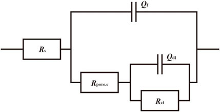
Figure 13. Fitted circuits for coupled pairs of small anodes immersed for 1d, 4d, 10d, 16d and 40d in a cooling water environment at 50°C.
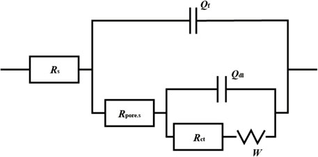
Figure 14. Fitted circuits for coupled pairs of small anodes immersed in a cooling water environment at 50°C for 22d and 30d.
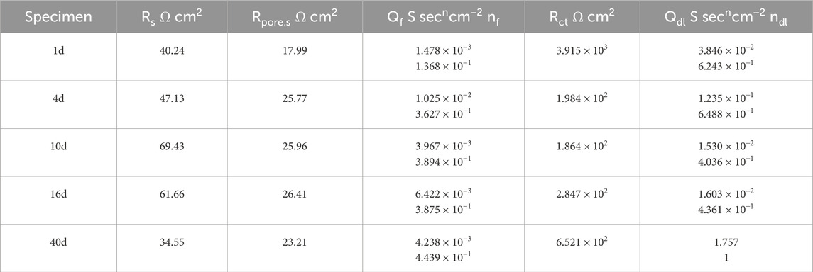
Table 5. Results of 1d, 4d, 10d, 16d, and 40d fitting of 30% exposed area of coupling to small anode in 50°C cooling water environment.
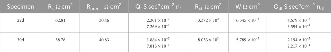
Table 6. Results of 22d and 30 d fitting of the coupling to small anodes with 30% exposure area in 50°C cooling water environment.
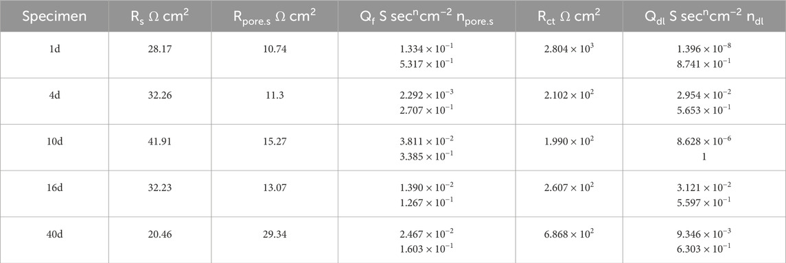
Table 7. 1d, 4d, 10d, 16d, and 40d fitting results of 60% exposure area of coupling to small anodes in 50°C cooling water environment.
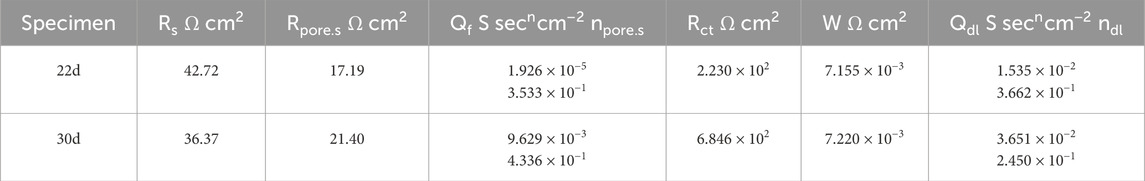
Table 8. Results of 22d and 30d fitting of 60% exposed area of coupling to small anode in 50°C cooling water environment.
Figure 15 shows the EIS of small anodes with different exposed areas immersed for 40 days in a cooling water environment. The fitted data reveals that the Rct values of the small anode generally follow a trend of decreasing, increasing, and then decreasing again. Initially, both small anodes with different exposed areas exhibit higher Rct values. This is because, in the early stages of immersion, a passive oxide film forms on the exposed surface of the small anode (Lavigne et al., 2011), which reduces its electrochemical activity, providing some degree of corrosion resistance. As immersion time increases, the oxide film is damaged, and the metal surface of the anode begins to make contact with the solution. For the small anode with 30% exposed area, the Rct value gradually decreases between 1–10 days as the oxide film on the anode surface dissolves with increasing immersion time, and corrosion phenomena begin to appear along with the generation of corrosion products. Between 10–22 days, with continued immersion in high-temperature cooling water, the corrosion products on the anode surface gradually become denser, forming a corrosion product film. This dense corrosion product film adsorbs onto the metal surface, providing a certain degree of corrosion inhibition, causing a decrease in corrosion on the anode surface and a continuous increase in Rct. From 22 to 30 days, the corrosion products continue to accumulate densely, expanding the area of the corrosion product film. Diffusion phenomena occur, and the ion exchange between the metal surface and the solution must pass through the dense corrosion product film, which suppresses anode corrosion. At day 30, due to the smaller exposed area and continued dense accumulation of corrosion products, the effective working area of the anode surface is significantly reduced, and the corrosion inhibition effect of the corrosion product film reaches its peak, greatly inhibiting the corrosion of the anode metal. From 30 to 40 days, as the immersion continues in high-temperature cooling water, the corrosion inhibition effect of the corrosion product film gradually fades, and the anode corrosion accelerates again, causing a decrease in Rct. For the small anode with 60% exposed area, during the first 1–4 days, the failure of the metal oxide film increases the metal surface activity, and the anode begins to corrode, resulting in a sharp decrease in Rct. With continued immersion in high-temperature cooling water from 4 to 10 days, corrosion products start to form on the anode metal surface. Although, due to the larger exposed area of the anode, the formation of the corrosion product film is relatively slow and its coverage is limited, the corrosion products adhere tightly to the metal, hindering ion exchange and still providing some corrosion inhibition (Foss et al., 2010). During this period, Rct continues to decrease, but at a slower rate. Between 10–16 days, Rct increases again, partly due to the dense accumulation of corrosion products providing some corrosion inhibition and reducing the effective exposed area of the anode. On the other hand, gaps appear under the cathodic coating, allowing solution to penetrate through fine holes and make contact with the metal substrate, leading to cathodic corrosion, which partially alleviates the anodic corrosion by sharing the galvanic current. From 16 to 22 days, corrosion products begin to form in the gaps under the cathodic coating (Emad et al., 2025), suppressing cathodic corrosion and further accelerating anodic corrosion, causing a temporary drop in Rct. As immersion time continues, the corrosion products on the anode surface accumulate, and the corrosion product film becomes increasingly dense. Although it does not fully cover the metal surface, its corrosion inhibition effect becomes more significant. From 22 to 30 days, diffusion phenomena occur on the metal surface, and the Rct value increases substantially. From 30 to 40 days, the corrosion product film on the anode metal surface becomes very dense, providing significant corrosion inhibition. Comparing the small anode impedance for the two different exposed areas, it is found that the smaller exposed area of the anode results in more severe corrosion. However, due to the smaller exposed area, the corrosion product film forms more quickly and densely, providing a more prominent corrosion inhibition effect, but it is also more prone to penetration.
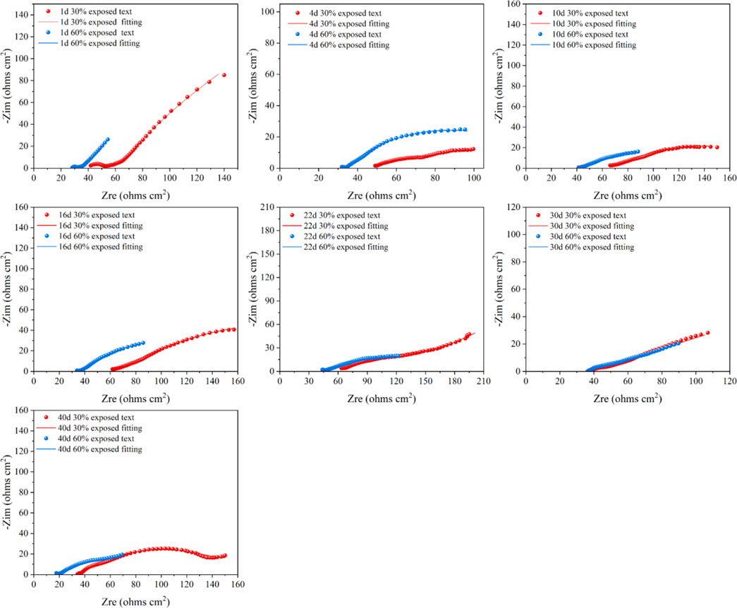
Figure 15. Electrochemical impedance spectra of small anodes immersed for 40d in 50°C cooling water environment with different exposure area coupling pairs.
3.6 Surface morphology analysis
Figure 16 shows the surface morphology of small anodes with different exposed areas after being immersed for 40 days in a 50°C cooling water environment. After immersion in high-temperature cooling water, the small anodes exhibited varying degrees of corrosion. From the images, it can be seen that during the early stages of immersion, an oxide film forms on the anode surface, providing some protection to the metal. Therefore, the corrosion on the surface of the small anodes with both exposed areas is not severe (Figures 16a,b). As immersion time increases, the oxide film is damaged, and corrosion begins to appear on the small anodes (Figures 16c,d). It is observed that the corrosion on the small anodes is primarily uniform, accompanied by localized corrosion. This is due to the uneven surface current distribution on the sandblasted anode surfaces, where local current densities are too high, resulting in intensified localized corrosion. Among them, the small anode with 30% exposed area exhibits more severe uniform corrosion. After 40 days, both small anodes with different exposed areas show significant corrosion, with the metal substrate of the 30% exposed area anode still exhibiting more severe corrosion than the 60% exposed area anode (Figures 16e,f). Although the corrosion of the 60% exposed area anode is mainly localized, deep corrosion pits caused by localized corrosion can still be observed on its surface.
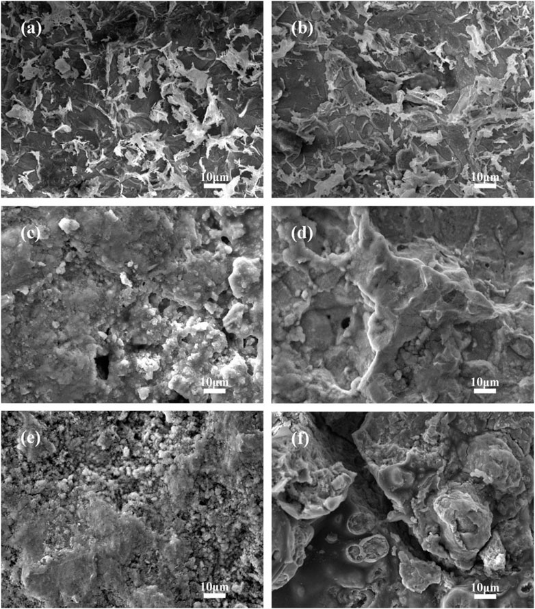
Figure 16. Surface morphology of small anode immersed for 40d in 50°C cooling water environment with different exposure area coupling pairs (a) 4d 30% exposure area small anode; (b) 4d 60% exposure area small anode; (c) 16d 30% exposure area small anode; (d) 16d 60% exposure area small anode; (e) 40d 30% exposure area small anode; (f) 40d 60% exposure area small anodes.
Comparing the small anodes with different exposed areas, both types of anodes exhibited uniform corrosion, along with localized corrosion. Typically, to improve the bonding strength of the coating to the metal, sandblasting is applied to the metal surface before coating (Benea et al., 2020). After the coating accidently detaches, the sandblasted metal substrate is exposed to the cooling water solution. While sandblasting enhances the adhesion of the coating, it also causes uneven current distribution on the exposed metal surface. This leads to a high local current density, which intensifies localized corrosion, resulting in corrosion pits, cracks, and other forms of damage. The small anode with a smaller exposed area shows more severe uniform corrosion compared to the larger exposed area anode. Additionally, the localized corrosion on the larger exposed area anode is more pronounced than that on the smaller exposed area anode. This is because the smaller exposed area generates a higher galvanic current density, causing both the corrosion rate and the formation of the corrosion product film to increase more rapidly. In contrast, the larger exposed area anode, although having a lower galvanic current density and experiences a slower corrosion rate. However, the larger exposed area combined with the slower accumulation of corrosion products leads to areas where dense corrosion products coexist with exposed metal regions. As a result, local current density becomes more concentrated, further intensifying localized corrosion. In actual working environments, when the coating first begins to peel off, uniform corrosion predominates. As high-temperature cooling water continues to immerse and erode the surface, the exposed area of the coating expands, and localized corrosion starts to develop. This is accompanied by the localized accumulation of corrosion products. As a result, local current density increases at the exposed surface, exacerbating localized corrosion and leading to the formation of corrosion pits and cracks.
3.7 Corrosion product analysis
The corrosion products formed on different anode exposure areas coupled in a 50°C cooling water environment for 40 days were analyzed using X-ray diffraction (XRD), as shown in Figure 17. The cooling water contains ions such as NaOH and K2PO4, with the primary corrosive ions being (OH)-, PO42-, and others. The XRD analysis of the corrosion products revealed that they primarily consist of FeO(OH), Fe2O3, and Fe(OH)3. These iron oxides formed and adhered to the metal surface, providing some level of corrosion protection. The formation of iron compounds and their adhesion to the metal surface provided some corrosion protection; however, they also contributed to the intensification of localized corrosion on the anode surface to some extent. By comparing the composition of corrosion products at different immersion times for the two exposure areas, it can be observed that as the immersion time increases, the corrosion products transition from FeO(OH) and Fe2O3 to the more stable Fe(OH)3 and Fe+3O(OH). This indicates that the corrosion process gradually stabilizes over time. Specifically, in the early immersion stage, the corrosion products of the 30% exposure area anode mainly consist of FeO(OH) and Fe2O3, while those of the 60% exposure area anode are primarily Fe2O3. This suggests that the anode with a smaller exposure area undergoes more severe corrosion, resulting in a higher corrosion rate and more complex corrosion products. In contrast, the anode with a larger exposure area experiences stronger polarization effects, leading to simpler corrosion products. As immersion time increases, by the 16th day, the corrosion products of the 30% exposure area anode mainly consist of Fe+3O(OH), Fe2O3, and Fe(OH)3, while those of the 60% exposure area anode primarily include Fe+3O(OH) and Fe(OH)3. The presence of Fe(OH)3 as an oxidation product of FeO(OH) indicates that the corrosion process is evolving towards a more stable state, with corrosion products becoming more hydrated and less compact. By the 40th day, the corrosion products of both exposure areas converge, consisting mainly of Fe+3O(OH) and Fe2O3. This suggests that despite the difference in exposure areas, the corrosion mechanisms are similar, ultimately leading to the formation of stable iron oxide products. Consequently, as immersion time increases, the corrosion products tend to transform into more stable forms, signifying that the corrosion process has entered a relatively stable phase.
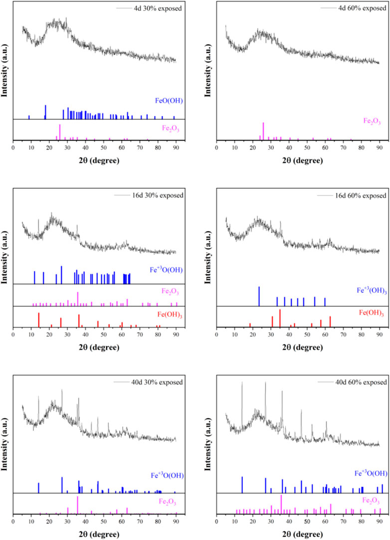
Figure 17. XRD analysis of small anodic corrosion products in cooling water environment at 50°C with different exposure area coupling on immersion for 40d.
Overall, in the early immersion stage, the corrosion products of the 30% exposure area anode are more complex, indicating more severe corrosion. As immersion time increases, the corrosion products of both exposure areas transition from FeO(OH) and Fe2O3 to the more stable Fe+3O(OH) and Fe(OH)3, eventually becoming consistent. This suggests that the corrosion process stabilizes over time. When the anode exposure area is smaller, corrosion is concentrated in the anode region, leading to more complex corrosion products. In contrast, when the anode exposure area is larger, the corrosion process develops more slowly. The corrosion products of both exposure areas provide a certain degree of corrosion inhibition to the metal substrate.
4 Conclusion
Through the analysis of galvanic current, current density, galvanic potential measurements, macroscopic corrosion morphology, SEM analysis, EIS analysis, and corrosion product analysis for different anode exposure areas coupled in a 50°C cooling water environment after 40 days of immersion, the changes in carbon steel corrosion behavior under different coating damage rates were explored. The study found:
1. As the exposure area decreased, the corrosion of the exposed small anode in the galvanic couple intensified. Additionally, regardless of the exposure area, as immersion time increased, the adhesion between the large cathodic coating and the metal substrate weakened, leading to the formation of voids. This allowed the electrolyte to infiltrate into the gaps and make contact with the metal substrate. The corrosion products generated provided some corrosion protection for the metal substrate, but at the same time, they further enlarged the gaps, promoting the progression of corrosion.
2. The galvanic couple with a smaller exposure area experienced more severe corrosion of the small anode, but the large cathode coupled with it exhibited a weaker corrosion tendency and less severe corrosion.
3. In practical working environments, when a small coating defect occurs, corrosion tends to develop in the exposed substrate area. In contrast, when a larger coating area is damaged, corrosion develops within the coating and continues to expand until the coating completely fails.
In practical working environments, to effectively mitigate coating failure in cooling water heat exchangers, enhance the protective efficiency of the coating on the metal substrate, and ensure the safe operation of the heat exchanger, comprehensive protection measures can be implemented from the following aspects.
1. Select corrosion-resistant coatings with high-temperature and hydrolysis resistance to minimize adhesion degradation and localized peeling failure.
2. Regularly inspect the integrity of the coating and promptly repair any localized damage to prevent intensified localized corrosion and expansion of exposed areas caused by coating detachment.
3. Implement sacrificial anode or impressed current cathodic protection methods to reduce the cathodic driving force on the anode, thereby mitigating localized corrosion.
4. Choose more corrosion-resistant materials, such as low-alloy corrosion-resistant steel or stainless steel, to enhance the corrosion resistance of the substrate. When designing heat exchangers, avoid dead zones and gaps to reduce localized corrosion caused by electrolyte retention.
5. Install corrosion sensors and electrochemical monitoring devices to continuously track parameters such as corrosion current, corrosion potential, and EIS, allowing for the prediction of corrosion trends. Utilize artificial intelligence analysis techniques to establish a corrosion failure early warning system, enabling timely maintenance and decision-making.
In conclusion, implementing these methods can improve the coating’s protective efficiency for heat exchangers, extend the lifespan of the equipment, and ensure the safety of personnel and the smooth operation of production.
Data availability statement
The original contributions presented in the study are included in the article/supplementary material, further inquiries can be directed to the corresponding authors.
Author contributions
ZZ: Conceptualization, Data curation, Formal Analysis, Methodology, Resources, Supervision, Validation, Writing – original draft. ZY: Supervision, Writing – review and editing. QH: Software, Writing – review and editing. KR: Data curation, Formal Analysis, Supervision, Writing – review and editing. JZ: Conceptualization, Funding acquisition, Project administration, Resources, Supervision, Writing – review and editing. CZ: Supervision, Writing – review and editing. RZ: Software, Validation, Writing – review and editing. WS: Software, Writing – review and editing. ZH: Supervision, Validation, Writing – review and editing. XC: Validation, Writing – review and editing. JD: Methodology, Writing – review and editing. BH: Methodology, Software, Writing – review and editing.
Funding
The author(s) declare that financial support was received for the research and/or publication of this article. This research was funded by the Major Basic Research Project of Natural Science Foundation of Shandong Province (No. ZR2023ZD31) and the National Natural Science Foundation of China (No. 42076043).
Conflict of interest
Authors QH and CZ were employed by Wanhua Chemical Group Co.
The remaining authors declare that the research was conducted in the absence of any commercial or financial relationships that could be construed as a potential conflict of interest.
Generative AI statement
The author(s) declare that no Generative AI was used in the creation of this manuscript.
Publisher’s note
All claims expressed in this article are solely those of the authors and do not necessarily represent those of their affiliated organizations, or those of the publisher, the editors and the reviewers. Any product that may be evaluated in this article, or claim that may be made by its manufacturer, is not guaranteed or endorsed by the publisher.
References
Ali, M., Ul-Hamid, A., Khan, T., Bake, A., Butt, H., Bamidele, O. E., et al. (2021). Corrosion-related failures in heat exchangers. Corros. Rev. 39, 519–546. doi:10.1515/corrrev-2020-0073
Benea, L., Simionescu, N., and Mardare, L. (2020). The effect of polymeric protective layers and the immersion time on the corrosion behavior of naval steel in natural seawater. J. Mater. Res. Technol. 9, 13174–13184. doi:10.1016/j.jmrt.2020.09.059
Bhuvanendran Nair Jayakumari, A., Malik, N. G., Mittal, G., Martelo, D., Kale, N., and Paul, S. (2023). A review on geothermal heat exchangers: challenges, coating methods, and coating materials. Coatings 13, 1988. doi:10.3390/coatings13121988
Chen, L., Daniel, E. F., Wang, C., Liu, C., Li, C., Ma, C., et al. (2023). Galvanic corrosion behavior of Cu-Fe-Zn trimetallic couple in acidic media. Electrochimica Acta 462, 142744. doi:10.1016/j.electacta.2023.142744
Chen, T., Wang, B., Sun, L., Liu, C., Cheng, X., and Li, X. (2024). The coupling mechanism of shrinkage defects and graphite on the corrosion resistance of ductile iron. Corros. Sci. 227, 111798. doi:10.1016/j.corsci.2023.111798
Choudhary, S., Garg, A., and Mondal, K. (2016). Relation between open circuit potential and polarization resistance with rust and corrosion monitoring of mild steel. J. Materi Eng Perform 25, 2969–2976. doi:10.1007/s11665-016-2112-6
Curioni, M., Cottis, R. A., and Thompson, G. E. (2013). Application of electrochemical noise analysis to corroding aluminium alloys. Surf. and Interface Analysis 45, 1564–1569. doi:10.1002/sia.5173
Dong, C. F., Xiao, K., Li, X. G., and Cheng, Y. F. (2010). Erosion accelerated corrosion of a carbon steel–stainless steel galvanic couple in a chloride solution. Wear 270, 39–45. doi:10.1016/j.wear.2010.09.004
Emad, S., Coghlan, L., Zhong, X., Burnett, T. L., Borwankar, K., Morsch, S., et al. (2025). High resolution analytical microscopy of damage progression within a polyester powder coating after cyclic corrosion testing. Prog. Org. Coatings 200, 108965. doi:10.1016/j.porgcoat.2024.108965
Faes, W., Lecompte, S., Ahmed, Z. Y., Van Bael, J., Salenbien, R., Verbeken, K., et al. (2019). Corrosion and corrosion prevention in heat exchangers. Corros. Rev. 37, 131–155. doi:10.1515/corrrev-2018-0054
Fedrizzi, L., Andreatta, F., Paussa, L., Deflorian, F., and Maschio, S. (2008). Heat exchangers corrosion protection by using organic coatings. Prog. Org. Coatings 63, 299–306. doi:10.1016/j.porgcoat.2008.01.009
Feliu, S., García-Galvan, F. R., Llorente, I., Diaz, L., and Simancas, J. (2017). Influence of hydrogen bubbles adhering to the exposed surface on the corrosion rate of magnesium alloys AZ31 and AZ61 in sodium chloride solution. Mater. and Corros. 68, 651–663. doi:10.1002/maco.201609233
Foss, M., Gulbrandsen, E., and Sjöblom, J. (2010). Oil wetting and carbon dioxide corrosion inhibition of carbon steel with ferric corrosion products deposits. Corrosion 66, 025005-1–025005-11. doi:10.5006/1.3319662
Hemkemeier, T. A., Almeida, F. C. R., Sales, A., and Klemm, A. J. (2022). Corrosion monitoring by open circuit potential in steel reinforcements embedded in cementitious composites with industrial wastes. Case Stud. Constr. Mater. 16, e01042. doi:10.1016/j.cscm.2022.e01042
Kazi, S. N. (2020). Fouling and fouling mitigation of calcium compounds on heat exchangers by novel colloids and surface modifications. Rev. Chem. Eng. 36, 653–685. doi:10.1515/revce-2017-0076
Kuźnicka, B. (2009). Erosion–corrosion of heat exchanger tubes. Eng. Fail. Anal. 16, 2382–2387. doi:10.1016/j.engfailanal.2009.03.026
Lavigne, O., Takeda, Y., Shoji, T., and Sakaguchi, K. (2011). Water irradiation by high-frequency ultrasonic wave: effects on properties of passive film formed on stainless steel. Ultrason. Sonochemistry 18, 1287–1294. doi:10.1016/j.ultsonch.2011.04.003
Li, Y., Sang, J., Yang, Y., Fang, G., Pang, J., and Liu, F. (2024). Galvanic corrosion behavior of the X80 steel welded joint. Coatings 14, 528. doi:10.3390/coatings14050528
Li, Z., Li, C., Qian, H., Li, J., Huang, L., and Du, C. (2017). Corrosion behavior of X80 steel with coupled coating defects under alternating current interference in alkaline environment. Materials 10, 720. doi:10.3390/ma10070720
Liu, Q., Li, N., Duan, J., Song, M., and Shi, F. (2024). Enhancing corrosion resistance and heat transfer performance of fin-tube heat exchangers for closed-type heat-source towers by superhydrophobic coatings. J. Build. Eng. 96, 110568. doi:10.1016/j.jobe.2024.110568
Michel, A., Sørensen, H. E., and Geiker, M. R. (2021). 5 years of in situ reinforcement corrosion monitoring in the splash and submerged zone of a cracked concrete element. Constr. Build. Mater. 285, 122923. doi:10.1016/j.conbuildmat.2021.122923
Moradighadi, N., Nesic, S., and Tribollet, B. (2021). Identifying the dominant electrochemical reaction in electrochemical impedance spectroscopy. Electrochimica Acta 400, 139460. doi:10.1016/j.electacta.2021.139460
Mousavian, R. T., Hajjari, E., Ghasemi, D., Manesh, M. K., and Ranjbar, K. (2011). Failure analysis of a shell and tube oil cooler. Eng. Fail. Anal. 18, 202–211. doi:10.1016/j.engfailanal.2010.08.022
Nakagawa, T., Sumi, R., and Kaneko, H. (2010). Galvanic corrosion of a Fe-Zn couple in a NaCl solution under high pressure O2-CO2 mixtures and a high temperature. J. Jpn. Inst. Met. 74, 77–84. doi:10.2320/jinstmet.74.77
Okonkwo, B. O., Ming, H., Meng, F., Wang, J., Xu, X., and Han, E.-H. (2021). Galvanic corrosion study between low alloy steel A508 and 309/308 L stainless steel dissimilar metals: a case study of the effects of oxide film and exposure time. J. Nucl. Mater. 548, 152853. doi:10.1016/j.jnucmat.2021.152853
Omar Rihan, R. (2014). Galvanic corrosion of electric resistance welded X52 steel in CO2 -containing solution. Anti-Corrosion Methods Mater. 61, 431–435. doi:10.1108/ACMM-08-2013-1299
Ribeiro, D. V., and Abrantes, J. C. C. (2016). Application of electrochemical impedance spectroscopy (EIS) to monitor the corrosion of reinforced concrete: a new approach. Constr. Build. Mater. 111, 98–104. doi:10.1016/j.conbuildmat.2016.02.047
Shamsa, A., Barker, R., Hua, Y., Barmatov, E., Hughes, T. L., and Neville, A. (2021). Impact of corrosion products on performance of imidazoline corrosion inhibitor on X65 carbon steel in CO2 environments. Corros. Sci. 185, 109423. doi:10.1016/j.corsci.2021.109423
Sharma, P., and Roy, H. (2015). Mill scale corrosion and prevention in carbon steel heat exchanger. High Temp. Mater. Process. 34. doi:10.1515/htmp-2014-0115
Song, S., Song, G.-L., Shen, W., and Liu, M. (2012). Corrosion and electrochemical evaluation of coated magnesium alloys. CORROSION 68, 015005-1–015005-12. doi:10.5006/1.3674295
Wang, C., Li, W., Wang, Y., Xu, S., and Yang, X. (2019). Chloride-induced stray current corrosion of Q235A steel and prediction model. Constr. Build. Mater. 219, 164–175. doi:10.1016/j.conbuildmat.2019.05.113
Wang, K., Li, C., Li, Y., Lu, J., Wang, Y., and Luo, X. (2021). Multi-physics analysis of the galvanic corrosion of Mg-steel couple under the influence of time-dependent anisotropic deposition film. J. Magnesium Alloys 9, 866–882. doi:10.1016/j.jma.2020.11.022
Wang, S.-S., Boerstler, J., and Frankel, G. S. (2018). Fundamental study of corrosion preventive compounds: Part II—effects on galvanic corrosion of coated Al alloy panels coupled to noble fasteners. Corrosion 74, 499–508. doi:10.5006/2654
Yang, L., and Yang, A. A. (2017). Communication—on zero-resistance ammeter and zero-voltage ammeter. J. Electrochem. Soc. 164, C819–C821. doi:10.1149/2.1421713jes
Yang, Z.-G., Gong, Y., and Yuan, J.-Z. (2012). Failure analysis of leakage on titanium tubes within heat exchangers in a nuclear power plant. Part I: electrochemical corrosion. Mater. and Corros. 63, 7–17. doi:10.1002/maco.201106189
Yoo, J. D., Ogle, K., and Volovitch, P. (2014). The effect of synthetic zinc corrosion products on corrosion of electrogalvanized steel. II. Zinc reactivity and galvanic coupling zinc/steel in presence of zinc corrosion products. Corros. Sci. 83, 32–37. doi:10.1016/j.corsci.2013.12.024
Zhang, X., Mei, W., Huang, L., Tao, J., Xiong, Y., and Wang, Z. (2023). Galvanic corrosion behavior of 5083 alloy/H62 brass couple under magnetic field. J. Mater. Res. Technol. 22, 192–205. doi:10.1016/j.jmrt.2022.11.140
Zhang, Y., Wang, S., Zhang, W., Ding, Y., Cheng, M., Mu, L., et al. (2022). Investigation of the condensation heat-transfer between the wet air and 3-D finned-tube heat exchanger surface with different anti-corrosion coatings. Exp. Heat. Transf. 35, 399–418. doi:10.1080/08916152.2021.1877371
Zhong, C., Tang, X., and Cheng, Y. F. (2008). Corrosion of steel under the defected coating studied by localized electrochemical impedance spectroscopy. Electrochimica Acta 53, 4740–4747. doi:10.1016/j.electacta.2008.02.014
Keywords: cooling water heat exchangers, organic coatings, chemical process safety, corrosion, coating breakage
Citation: Zuo Z, Yu Z, Hou Q, Ren K, Zhang J, Zhang C, Zhang R, Sand W, Hu Z, Chen X, Duan J and Hou B (2025) Study on galvanic corrosion caused by coating failure in heat exchangers for chemical cooling water systems. Front. Mater. 12:1580067. doi: 10.3389/fmats.2025.1580067
Received: 20 February 2025; Accepted: 21 April 2025;
Published: 15 May 2025.
Edited by:
Pan Liu, Tohoku University, JapanReviewed by:
Pavlo Maruschak, Ternopil Ivan Pului National Technical University, UkraineJihui Wang, Tianjin University, China
Copyright © 2025 Zuo, Yu, Hou, Ren, Zhang, Zhang, Zhang, Sand, Hu, Chen, Duan and Hou. This is an open-access article distributed under the terms of the Creative Commons Attribution License (CC BY). The use, distribution or reproduction in other forums is permitted, provided the original author(s) and the copyright owner(s) are credited and that the original publication in this journal is cited, in accordance with accepted academic practice. No use, distribution or reproduction is permitted which does not comply with these terms.
*Correspondence: Jie Zhang, emhhbmdqaWVAcWRpby5hYy5jbg==; Ruiyong Zhang, cnVpeW9uZy56aGFuZ0BxZGlvLmFjLmNu