 Lu Wang
- School of Civil Engineering, Liaodong University, Dandong, China
In order to study the influence of confining pressure on the deformation of concrete, triaxial compression and creep tests under different confining pressures are carried out using a combination of laboratory tests and theoretical analysis. Based on the whole creep process curve of concrete and the energy conservation theorem, viscoplastic and accelerated creep models are established by introducing loading rate equations at different stages. Taking time and stress as the triggering conditions of the creep model, the model parameters are identified by fitting the test curve, and a nonlinear creep damage model is established, which can better reflect the creep development characteristics of concrete. The results showed that the fitting curves closely matched the test results. The newly established damage creep model can better describe the deformation characteristics of the creep failure stage under different confining pressures and stress levels. It can effectively describe the nonlinear creep development trend of concrete during the accelerated creep stage. In general, the creep model has a high degree of accuracy in capturing the damage description of concrete.
1 Introduction
With the improvement in China’s economic construction level and the increasing social demand, infrastructure construction is developing rapidly (Zhong, 2006; Wang and Liew, 2016; Yun et al., 2024). Concrete materials play an irreplaceable role in various engineering construction projects. Concrete materials have many advantages such as strong adaptability, low cost, high compressive strength, and simple construction. It is widely used in major construction projects such as high-rise buildings, tunnel linings, roads, and bridges (Roeder and Brown, 1999). It has become the main component of building structures in today’s era, and it is one of the building materials with the largest application range and amount in civil engineering. According to the statistics of the concrete industry, China’s commercial concrete production has reached 3.293 billion square meters in 2022, an increase of 15.83% year-on-year. Nowadays, China is in a high-speed period of infrastructure construction and development (Pignatelli et al., 2016). Concrete still occupies an important position in the field of engineering construction. However, compared with the rapid development of concrete engineering construction projects year by year, the research on concrete mechanics is relatively lagging (Cascardi et al., 2024). In particular, it is still a challenging problem to study the mechanical properties and damage of concrete under complex stresses such as dynamic loads (Zhang et al., 2017).
Concrete material is a composite material composed of cement, sand, water, and other materials. Due to the complexity and diversity of the material structure, the analysis of its mechanical properties and failure deformation has always been the focus of many scholars. Any material in nature has certain rheological properties. In construction projects, most material failures do not occur instantaneously but rather evolve gradually over time (Bary et al., 2013). Concrete materials are no exception. Under a long-term load, the deformation of concrete structures will gradually accumulate and increase with time. This phenomenon is called concrete creep, also known as concrete creep deformation (Zhang et al., 2014; ACI, 2019; Bažant and Jirásek, 2018). Creep deformation has a great influence on the safety of its structure. In many concrete projects, the creep deformation of concrete structures is observed to increase gradually with time. In severe cases, it is several times higher than the instantaneous strain value. For concrete materials, creep deformation will cause cracks in the concrete structure. Cracks will continue to develop over time. The long-term action will cause damage to the concrete structure. In construction engineering, damages such as concrete dam cracks and shaft wall concrete rupture, etc., are related to the creep characteristics of concrete. At the same time, concrete has a complex internal structure, and a large number of microcracks and small voids are distributed in the early stage of formation (Huang and Hamed, 2013; Zhang et al., 2013). Under the long-term external stress of concrete, the cracks inside the structure will gradually develop and eventually form macroscopic cracks. This leads to a decrease in the strength and stiffness of concrete, thus affecting the stability and durability of the structure. Therefore, it is of great engineering value to study the creep deformation and failure of concrete. It can provide a theoretical basis and reference for the safety and stability of concrete engineering (Charpin et al., 2018). A full understanding of creep properties is also crucial for the mechanical behavior and long-term stability of concrete structures (Wendner et al., 2013).
The relationship between stress, strain, and time can be obtained by the creep test. The creep constitutive relationship is derived from the establishment of the rheological model. As early as the last century, Kelvin and Bergs et al. found that the deformation of the material is closely related to the load time through relevant tests. Based on the test, the use of elasticity, plasticity, viscosity, or a combination of the three has been proposed to represent the rheological properties of the material. Studies have shown that when concrete is subjected to large stress loads for a long time, the linear creep of concrete will evolve into nonlinear creep. How to describe the creep characteristics of concrete materials in the three stages of primary, steady-state, and accelerated creep has become the focus of many scholars. Liu et al. (2021) analyzed the creep characteristics of concrete under water–rock coupling and the relationship between the water content and creep deformation of concrete. Considering the damage caused by water–rock coupling and stress, a time-varying creep model of concrete with different water contents was established. This model not only accurately reflected the creep characteristics of the primary and steady-state creep stages but also overcame the shortcomings of the traditional Nishihara model. Zhang et al. (2022) conducted a 710-day creep test on high-performance concrete (HPC) with a loading period of 45–260 days. A creep model based on concrete was established and verified by experimental results. This study could provide a basis for the establishment of a creep model of high-performance concrete. Wang et al. (2019) proposed a nonlinear creep model for circular CFST columns. The model was benchmarked based on available experimental data. Extensive parametric studies were conducted to investigate the effect of nonlinear creep on the static response of circular CFST columns. Finally, the applicability of different algebraic methods in calculating the nonlinear creep response of circular CFST columns was evaluated based on the results obtained by the detailed analysis program. Zheng et al. (2022) characterized the weakening effect of water and overstress as a time-independent damage function and a time-dependent damage function, respectively. These were then combined and applied to a modified creep model that could represent the elastic–viscoplastic creep deformation of concrete. A damage creep model was proposed to describe the creep behavior of water-bearing concrete. Meng (2022) introduced the variable order fractional operator to capture the high-temperature creep behavior of concrete by assuming that the variable order function was a linear function over time. The proposed model benefited from a simple form and incorporated the physical significance of macroscopic intermediate materials. The validity of the model was proved by fitting the data with the experimental results of high-temperature creep of two representative concretes. Bu et al. (2023) introduced the damage variable into the creep constitutive equation and established a new creep damage coupling model. The model used the statistical damage theory framework and assumed that the damage variables follow the random distribution described by the Weibull function. The accuracy and applicability of the creep damage coupling model were verified.
Traditional studies on concrete creep predominantly rely on phenomenological models that describe material behavior through stress–strain–time relationships. Although these models can capture macroscopic deformation characteristics, they often fail to reveal the underlying physical mechanisms of internal damage evolution. In contrast, the modeling approach based on the energy conservation theorem offers distinct advantages: first, the energy method quantifies energy dissipation and release during deformation, directly linking the initiation and propagation of microcracks within concrete to macroscopic nonlinear creep behavior. This is particularly effective in characterizing the abrupt energy changes during the accelerated creep stage caused by cumulative damage. Second, the principle of energy conservation provides a unified framework for multiscale analysis, integrating energy dissipation mechanisms at the microstructural level (e.g., viscoplastic strain energy) while coupling macroscopic stress states with damage evolution. This enables a more comprehensive representation of the time-dependent behavior of concrete under complex stress conditions.
In this study, by introducing the energy dissipation coefficient λ and strain-rate-dependent functions, we explicitly express the differences in energy conversion between steady-state and accelerated creep stages, addressing the limitations of traditional models in describing nonlinear damage processes. The rationality and accuracy of the model are further validated through comparisons between experimental and theoretical curves. This energy-driven approach not only improves the fitting accuracy of the full-stage creep curve but also provides a more reliable physical basis for predicting the long-term stability of concrete in engineering applications.
2 Creep characteristics test of concrete under different temperatures
2.1 Preparation and processing of concrete samples
The concrete sample is composed of ordinary Portland cement, natural river sand, coarse aggregate, fly ash, a high-performance water reducing agent, and other such materials. The cement is P·O42.5 Portland cement, and the mechanical properties of the cement are shown in Table 1.
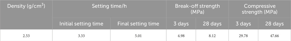
Table 1. Mechanical properties of cement.
The fine aggregate is natural river sand and machine-made sand. The fineness modulus of fine aggregate is 2.8, the apparent density is 2.60 g/cm3, and the mud content is not more than 2.0%. The coarse aggregate is local gravel, with a particle size gradation ranging from 5 mm to 25 mm, and the maximum particle size is 25 mm. F-grade-II fly ash was selected as the admixture. The water used is laboratory tap water. The water reducing agent is a polycarboxylate high-performance water reducing agent. The mix ratio of the C30 concrete sample used in this test is determined based on the concrete pile foundation ratio used at the actual construction site. The concrete specimens with a strength grade of C30 are shown in Table 2.
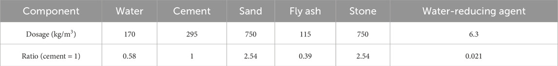
Table 2. Concrete specimens with a strength grade of C30.
The sample preparation process is as follows (Wu et al., 2021; Dusseault et al., 1993).
(1) The concrete test block is placed in a concrete curing box with a curing temperature of 20°C ± 2°C and humidity of 95%. After 28 days of curing, the concrete test block is taken out and then placed in an indoor ventilation shade.
(2) The drilling sampling equipment is used to sample the prepared concrete block.
(3) After the concrete coring is completed, the surface is polished and smoothed using the grinding machine. The diameter of the cylindrical concrete standard sample is 0 mm, and the height is 100 mm. The error of sample diameter and height is less than 0.3 mm.
(4) In order to reduce the influence of the friction effect at the end of the sample during the testing process, the vertical deviation angle error between the upper and lower ends of the sample and the axis of the sample is controlled to be less than 0.25. The non-parallelism error of the cylinder concrete end face is ±0.05 mm. These measurements meet the requirements of the testing specifications for the accuracy of the sample.
Some standard samples of concrete are processed as shown in Figure 1.
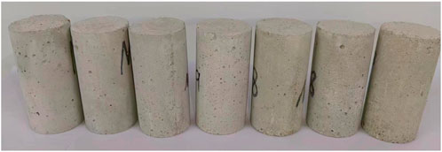
Figure 1. Some standard samples of concrete.
Figure 2 shows the fully automatic triaxial compression system, which was jointly developed by the Guilin University of Technology and the Institute of Rock and Soil Mechanics, Chinese Academy of Sciences. This equipment is capable of conducting triaxial compression and triaxial creep tests on both rocks and concrete.
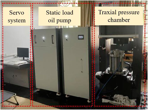
Figure 2. Fully automatic triaxial compression system.
2.2 Experiment on the mechanical properties of concrete
During the actual service of the concrete material, its structure is not a simple one-way or two-axis force. It is often in a complex triaxial stress state for a long time. The effect of confining pressure on the mechanical deformation characteristics of concrete materials is significant. Therefore, this experiment designed a triaxial compression failure test under different confining pressure conditions to study the mechanical properties of concrete. In this paper, the confining pressure is selected as 2 and 4 MPa. The stress–strain curves of concrete under different confining pressures are shown in Figure 3.
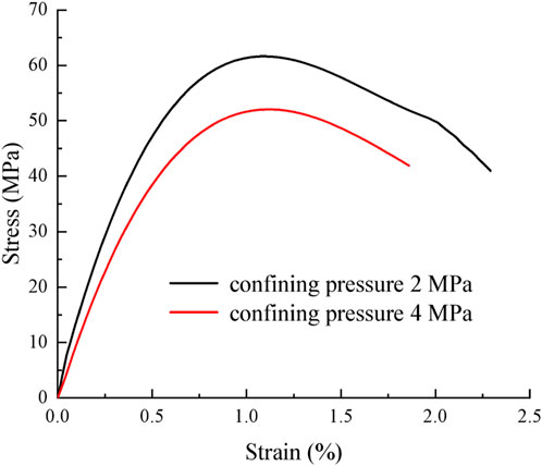
Figure 3. Stress–strain curves of concrete under different confining pressures.
Figure 3 shows that an increase in confining pressure also increases the peak strength and peak strain of concrete materials accordingly. The smaller the bending degree of the axial stress–strain curve, the smaller the decrease in stress.
2.3 Concrete creep test
Concrete creep test steps are as follows (Oggeri et al., 2022; Zhao et al., 2023; Wang X. K. et al., 2021).
1) The concrete specimen was installed on the test loading platform. The loading chamber must be lowered slowly and filled with hydraulic oil.
2) A loading speed of 0.1 MPa/s gradually loads the confining pressure to the experimental design value, and then the axial loading is carried out after the confining pressure is stable.
3) The axial load is loaded to a predetermined value at a loading speed of 0.5 kN/s, and the sampling interval is set to 1 s. Under the constant load, the stable creep stage is reached, and the next load test is entered.
4) When the concrete strain enters the stable creep stage, the next load is applied.
5) After the test is completed, the sample is taken off the oil. The damaged concrete sample is numbered and saved, the relevant test data are saved and processed, and the creep test of the next sample is carried out.
The specific creep curves under different confining pressures are shown in Figure 4.
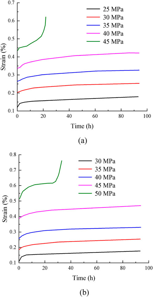
Figure 4. Specific creep curves under different confining pressures. (a) 2 MPa. (b) 4 MPa.
Figure 4 shows that when the load reaches the predetermined value of the test, the axial deformation of the concrete material under various loads will gradually accumulate with an increase in time. Concrete shows obvious creep characteristics. The axial strain of the specimen is composed of instantaneous deformation and creep deformation. After the specimen is deformed at the moment of loading, it enters the creep stage. Creep deformation tends to be stable with the accumulation of time. The creep strain value of the specimen also increases with an increase in the axial load stress level. Under the same stress level, the creep strain also increases slightly with an increase in confining pressure. When the specimen is subjected to a lower load, the axial strain reaches stability in a short time; the strain is mainly due to instantaneous deformation, with minimal creep deformation.
According to the data in Figure 4, the isochronous stress–strain curves of concrete under different confining pressures are drawn, as shown in Figure 5.
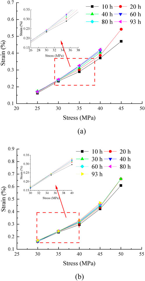
Figure 5. Isochronous stress–strain curves of concrete under different confining pressures. (a) 2 MPa. (b) 4 MPa.
Figure 5 shows that the isochronous stress–strain curve is a cluster of divergent curves. Before the divergence point, the rock exhibits linear characteristics. After the divergence point, the rock exhibits nonlinear characteristics. Therefore, the stress corresponding to the divergence point is taken as the long-term strength of concrete. When the confining pressure is 2 MPa, the long-term strength of concrete is 30 MPa. When the confining pressure is 4 MPa, the long-term strength of concrete is 35 MPa.
3 Nonlinear creep damage model of concrete
3.1 Viscoelastic–plastic creep model based on the energy principle
According to Wang X. et al. (2021), in the viscoelastic–plastic creep stage, the creep process of concrete and rock satisfies the principle of energy conservation.
where S is the end face area, L is the height, M is the mass, Δεvp is the microvolume viscoplasticity strain, λ is the energy dissipation coefficient, and Δv is the microvolume viscoplasticity strain rate.
When t < t1, concrete creep is in the stage of steady-state creep deformation. The creep deformation can be expressed as follows:
where a is a test variable related to stress.
By substituting Equation 2 into Equation 1, we obtain
The initial conditions are t = 0 and εvp1 = 0. By integrating Equation 3, we obtain
When t ≥ t1, concrete creep is in the stage of accelerated creep deformation. The creep deformation can be expressed as follows:
where b and c are test variables related to stress.
By substituting Equation 5 into Equation 1, we obtain
The initial conditions are t = 0 and εvp2 = 0. By integrating Equation 6, we obtain
In general, the instantaneous strain εe is
where Ee is the instantaneous elastic modulus.
3.2 Creep model of concrete under the one-dimensional stress state
The viscoelastic strain is
where Eve is the viscoelastic modulus and ηve refers to viscosity coefficients.
The total strain can be expressed as follows (Wang et al., 2020):
where εe is the elastic strain, εve is the viscoelastic strain, εvp1 is the viscoplastic strain, and εvp1 is the accelerated creep.
By substituting Equations 4, 7–9 into Equation 10, we obtain the following.
When t < t1 and σ≤σs,
When t < t1 and σ>σs,
When t > t1 and σ>σs,
Equations 11–13 is a creep damage model of concrete under one-dimensional stress state.
3.3 Creep model of concrete under the three-dimensional stress state
In practical engineering, concrete structures are rarely subjected to a one-dimensional stress state; instead, they are often subjected to two-dimensional or three-dimensional complex stress conditions (Bérest et al., 2019). For example, structures such as frame columns of high-rise buildings, bridge piers, and dams in hydraulic structures, not only bear vertical pressure but also bear the combination of horizontal shear force, bending moment, and other forces in the process of use, and their internal stress state is three-dimensional. If only the creep model under the one-dimensional stress state is used to evaluate the long-term deformation and performance of these structures, there will be a large deviation from the actual situation, and the creep behavior of the structure under the complex stress state cannot be accurately predicted, thus affecting the safety and durability evaluation of the structure (Hou et al., 2019).
The stress tensor σij can be decomposed into spherical stress tensor σm and deviatoric stress tensor Sij. Similarly, strain tensor εij can be decomposed into spherical strain tensor εm and deviatoric strain tensor eij (Sun et al., 2019).
where δij is the Kronecker function, the spherical stress tensor σm = (σ1 + 2σ3)/3, the spherical strain tensor εm = (ε1 + 2ε3)/3, and Sij = σij − σm (Sha et al., 2018).
where G is the initial shear modulus and K is the initial bulk modulus.
According to Equations 8, 14, 15, we obtain
where is Ge is the shear modulus, Ke is the bulk modulus, and ε11e is the instantaneous strain.
According to Equations 9, 14, 15, we obtain
where ε11ve is the viscoelastic strain, Ge is the shear modulus of the viscoelastic strain, and Hve is the viscosity coefficient of the viscoelastic strain.
The yield function can take the following form (Zhao et al., 2017):
where J2 is the second invariant of the stress tensor. In this paper, the concrete is a cylinder. The relationship between the various stresses is
Therefore, the yield function can be expressed as follows:
where J2 is the second invariant of the stress tensor.
When t < t1, the creep deformation ε11vp1 can be expressed as follows:
When t ≥ t1, the creep deformation ε11vp2 can be expressed as follows:
The total strain ε under the three-dimensional stress state can be expressed as follows:
where ε11e is the instantaneous strain under the three-dimensional stress state, ε11ve is the viscoelastic strain under the three-dimensional stress state, ε11vp1 is the viscoplastic strain under the three-dimensional stress state, and ε11vp1 is the accelerated creep under the three-dimensional stress state.
When t < t1 and σ≤σs,
By substituting Equations 16–22 into Equation 23, we obtain
When t < t1 and σ>σs,
When t > t1 and σ>σs,
Equations 24–26 is the creep damage model of concrete under three-dimensional stress state.
4 Model parameter identification and model validation
The nonlinear least squares method is used to fit the creep test data and identify the parameters (Yang et al., 2017). The parameter identification results of the creep test are shown in Table 3.
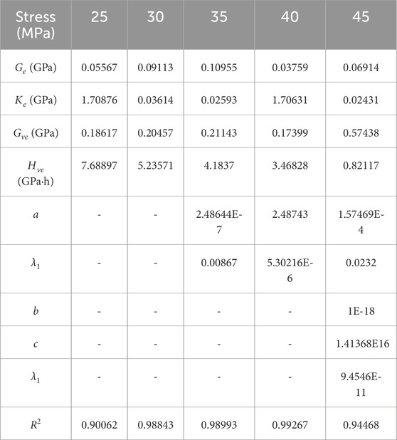
Table 3. Parameter identification results of the creep test.
The creep test data and creep model fitting curve of concrete under different levels of stress are compared and analyzed, as shown in Figure 6.
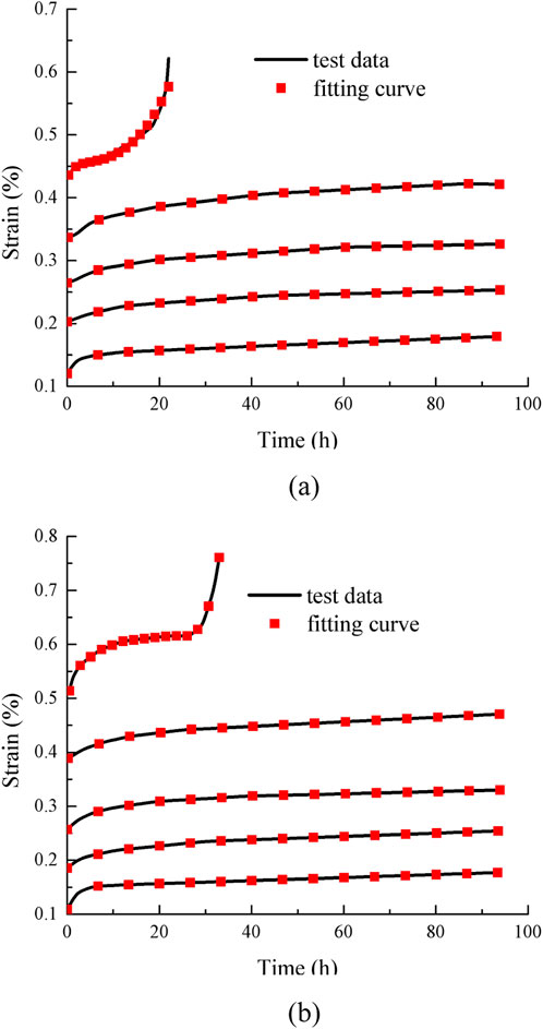
Figure 6. Comparison of creep fitting curve and experimental results under different confining pressures. (a) 2 MPa. (b) 4 MPa.
Figure 6 shows that the fitting curves closely match the test results. The newly established damage creep model can better describe the deformation characteristics of the creep failure stage under different confining pressures and different stress levels. It can effectively describe the nonlinear creep development trend of concrete during the accelerated creep stage. In general, the creep model has a high degree of fitting for the damage description of concrete, and it has certain theoretical guidance for practical projects, such as predicting the creep development of concrete and preventing the damage of creep failure.
As shown in Figure 7, the Nishihara model is a classical rheological model for describing the creep behavior of rocks and concrete. Its conventional nature is primarily reflected in its use of simple combinations of springs, dampers, and sliders to linearly simulate the material’s creep process. The model divides creep into three stages—deceleration, steady-state, and acceleration—through predefined mechanical components. Although it can preliminarily reflect the time-dependent characteristics of materials, its linear assumptions and lack of consideration for internal damage-energy mechanisms make it difficult to accurately describe the nonlinear damage evolution process under high stress, particularly in explaining the energy mutation phenomenon during the accelerated creep stage.
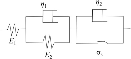
Figure 7. Classic Nishihara model.
To further demonstrate the superiority of the established model, a comparison between the Nishihara model and the model proposed in this study is presented in Figure 8.
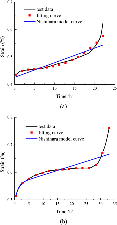
Figure 8. Comparison between the Nishihara model and the model in this paper. (a) 2 MPa. (b) 4 MPa.
Figure 8 shows that based on the principle of energy conservation, the whole process of concrete creep can be described more accurately, including the initial creep, steady-state creep, and accelerated creep stages. At different stages, the mechanism of energy conversion and dissipation in concrete is different. The model can reflect these changes through the corresponding energy equation. It provides a more accurate to fit to the test curve, especially for the prediction of the accelerated creep stage. Because accelerated creep is often accompanied by the aggravation of internal damage and the rapid release of energy in concrete, the description of the accelerated creep stage is relatively not ideal.
5 Conclusion
(1) The creep model of concrete is established based on the law of conservation of energy. The one-dimensional creep model is extended to three dimensions to better reflect the actual stress state. The model parameters are obtained by fitting, and the rationality of the model is verified by comparing the theoretical curve with the experimental results.
(2) The fitting curve and the test results are ideal. The newly established damage creep model can better describe the deformation characteristics of the creep failure stage under different confining pressures and different stress levels. It can effectively describe the nonlinear creep development trend of concrete during the accelerated creep stage. In general, the creep model provides a high degree of accuracy for the damage description of concrete.
(3) The axial strain of the specimen is composed of instantaneous deformation and creep deformation. After the specimen is deformed at the moment of loading, it enters the creep stage. Creep deformation tends to be stable with the accumulation of time. The creep strain value of the specimen also increases with the increase in the axial load stress level. Under the same stress level, the creep strain also increases slightly with an increase in confining pressure. When the specimen is subjected to a lower load, the axial strain reaches stability in a short time; the strain is mainly due to instantaneous deformation, with minimal creep deformation.
Data availability statement
The original contributions presented in the study are included in the article/supplementary material; further inquiries can be directed to the corresponding author.
Author contributions
LW: conceptualization, funding acquisition, writing – review and editing, writing – original draft, data curation, and methodology.
Funding
The author(s) declare that financial support was received for the research and/or publication of this article. This work was financially supported by the Dandong City Social Science Association Project (grant no. 2021DDSK126) and the school-level scientific research project of Liaodong University (grant no. XCZX20230208).
Conflict of interest
The author declares that the research was conducted in the absence of any commercial or financial relationships that could be construed as a potential conflict of interest.
Generative AI statement
The authors declare that no Generative AI was used in the creation of this manuscript.
Publisher’s note
All claims expressed in this article are solely those of the authors and do not necessarily represent those of their affiliated organizations, or those of the publisher, the editors and the reviewers. Any product that may be evaluated in this article, or claim that may be made by its manufacturer, is not guaranteed or endorsed by the publisher.
References
Bary, B., He, Q. C., and Thai, M. Q. (2013). “Coupled damage and multiscale creep model applied to cementitious materials,” in Proceedings of the International Conference on Creep, Shrinkage, and Durability Mechanics, Cambridge, CA, USA, 22–25 September 2013, 219–226.
Bažant, Z. P., and Jirásek, M. (2018). “Basic properties of concrete creep, shrinkage, and drying,” in Creep and hygrothermal effects in concrete structures (Basingstoke, UK: Springer).
Bérest, P., Gharbi, H., Brouard, B., Brückner, D., DeVries, K., Hévin, G., et al. (2019). Very slow creep tests on salt samples. Rock Mech. Rock Eng. 52, 2917–2934. doi:10.1007/s00603-019-01778-9
Bu, P., Li, Y., Li, Y., Wen, L., Wang, J., and Zhang, X. (2023). Creep damage coupling model of concrete based on the statistical damage theory. J. Build. Eng. 63, 105437. doi:10.1016/j.jobe.2022.105437
Cascardi, A., Verre, S., Ombres, L., and Aiello, M. A. (2024). Carbon Fabric Reinforced Cementitious Mortar confinement of concrete cylinders: the matrix effect for multi-ply wrapping. J. Compos. Struct. 332, 117919. doi:10.1016/j.compstruct.2024.117919
Charpin, L., Le Pape, Y., Coustabeau, É., Toppani, É., Heinfling, G., Le Bellego, C., et al. (2018). A 12 year EDF study of concrete creep under uniaxial and biaxial loading. Cem. Concr. Res. 103, 140–159. doi:10.1016/j.cemconres.2017.10.009
Dusseault, M. B., and Fordham, C. J. (1993). “Time-dependent behavior of rocks,” in Comprehensive rock engineering. Editor J. A. Hudson (Oxford, UK: Pergamon), 3, 119–149. doi:10.1016/b978-0-08-042066-0.50013-6
Hou, R., Zhang, K., Tao, J., Xue, X., and Chen, Y. A. (2019). A nonlinear creep damage coupled model for rock considering the effect of initial damage. Rock Mech. Rock Eng. 52, 1275–1285. doi:10.1007/s00603-018-1626-7
Huang, Y., and Hamed, E. (2013). Buckling of one-way high-strength concrete panels: creep and shrinkage effects. J. Eng. Mech. 139, 1856–1867. doi:10.1061/(asce)em.1943-7889.0000629
Liu, W., Zhang, S., Sun, B., and Chen, L. (2021). Creep characteristics and time-dependent creep model of tunnel lining structure concrete. Mech. Time-Dependent Mater. 25, 365–382. doi:10.1007/s11043-020-09449-x
Meng, R. (2022). Predicting the creep behavior of concrete at high temperature using the variable-order fractional model. Eng. Comput. 39 (7), 2532–2552. doi:10.1108/ec-09-2021-0524
Oggeri, C., Oreste, P., and Spagnoli, G. (2022). Creep behaviour of two-component grout and interaction with segmental lining in tunnelling. Tunn. Undergr. Space Technol. 119, 104216. doi:10.1016/j.tust.2021.104216
Pignatelli, I., Kumar, A., Alizadeh, R., Le Pape, Y., Bauchy, M., and Sant, G. (2016). A dissolution-precipitation mechanism is at the origin of concrete creep in moist environments. J. Chem. Phys. 145, 054701. doi:10.1063/1.4955429
Roeder, C. W., and Brown, C. B. (1999). Composite action in concrete filled tubes. J. Struct. Eng. 125, 477–484. doi:10.1061/(asce)0733-9445(1999)125:5(477)
Sha, Z., Pu, H., Li, M., Cao, L., Liu, D., Ni, H., et al. (2018). Experimental study on the creep characteristics of coal measures sandstone under seepage action. Processes 6, 110. doi:10.3390/pr6080110
Sun, Y., Li, G., Zhang, J., and Qian, D. (2019). Stability control for the rheological roadway by a novel high-efficiency jet grouting technique in deep underground coal mines. Sustainability 11, 6494. doi:10.3390/su11226494
Wang, X., Song, L., Xia, C., Han, G., and Zhu, Z. (2021). Nonlinear elasto-visco-plastic creep behavior and new creep damage model of dolomitic limestone subjected to cyclic incremental loading and unloading. Sustainability 13, 12376. doi:10.3390/su132212376
Wang, X., Xie, W., Bai, J., Jing, S., Su, Z., and Tang, Q. (2020). Control effects of pretensioned partially encapsulated resin bolting with mesh systems on extremely soft coal gateways: a large-scale experimental study. Rock Mech. Rock Eng. 53, 3447–3469. doi:10.1007/s00603-020-02141-z
Wang, X. K., Xia, C. C., Zhu, Z. M., Xie, W. B., Song, L. B., and Han, G. S. (2021). Long-term creep law and constitutive model of extremely soft coal rock subjected to single-stage load. Rock Soil Mech. 42, 2078–2088. doi:10.16285/j.rsm.2021.5178
Wang, Y. B., and Liew, J. R. (2016). Constitutive model for confined ultra-high strength concrete in steel tube. J. Constr. Build. Mater. 126, 812–822. doi:10.1016/j.conbuildmat.2016.09.079
Wang, Y. Y., Geng, Y., Zhao, M. Z., and Chen, J. (2019). Non-linear creep modelling on circular concrete-filled steel tubular columns. J. Constr. Steel Res. 159, 270–282. doi:10.1016/j.jcsr.2019.05.009
Wendner, R., Hubler, M. H., and Bažant, Z. P. (2013). “The B4 model for multi-decade creep and shrinkage prediction,” in Proceedings of the International Conference on Creep, Shrinkage, and Durability Mechanics, Cambridge, CA, USA, 22–25 September 2013, 429–436. doi:10.1061/9780784413111.051
Wu, K., Shao, Z., Qin, S., Wei, W., and Chu, Z. (2021). A critical review on the performance of yielding supports in squeezing tunnels. Tunn. Undergr. Space Technol. 115, 103815. doi:10.1016/j.tust.2021.103815
Yang, S.-Q., Tian, W. L., and Ranjith, P. G. (2017). Experimental investigation on deformation failure characteristics of crystalline marble under triaxial cyclic loading. Rock Mech. Rock Eng. 50, 2871–2889. doi:10.1007/s00603-017-1262-7
Yun, M. C., Ren, J. X., Zhang, L., and Chen, X. (2024). Fracture process and instability precursor determination of freeze-thaw red sandstone based on acoustic emission monitoring. J. Eksploatacja i Niezawodnosc – Maintenance Reliab. 26 (4), 191193. doi:10.17531/ein/191193
Zhang, Q., Le Roy, R., Vandamme, M., and Zuber, B. (2013). “Long-term creep properties of cementitious materials—comparing compression tests on concrete with microindentation tests on cement,” in Proceedings of the Fifth Biot Conference on Poromechanics (Poromechanics V), Vienna, Austria, 10–12 July 2013, 1596–1604.
Zhang, R. L., Wang, Q. C., Ma, L. N., Qi, L. F., and Qi, Q. (2017). Effect of expanding agent proportion and lateral confinement by steel tube on the creep strain of concrete. Acta Mater. Compos. Sin. 34, 2099–2105. doi:10.13801/j.cnki.fhclxb.20161207.002
Zhang, R. L., Wang, Q. C., Ma, L. N., Yang, Y., and Qi, L. F. (2014). Effect of expanding agent proportion and stress ratio on the creep characteristics of concrete filed steel tube. J. Cent. South Univ. Sci. Technol. 45, 2146–2423. doi:10.3969/j.issn.1007-9629.2015.05.006
Zhang, Y., Mao, J., Jin, W., and Zhang, J. (2022). Creep model of high-performance concrete at different loading ages. Constr. Build. Mater. 357, 129379. doi:10.1016/j.conbuildmat.2022.129379
Zhao, J. S., Jiang, Q., Pei, S. F., Chen, B. R., Xu, D. P., and Song, L. B. (2023). Microseismicity and focal mechanism of blasting-induced block falling of intersecting chamber of large underground cavern under high geostress. J. Cent. South Univ. 30, 542–554. doi:10.1007/s11771-023-5259-y
Zhao, Y., Wang, Y., Wang, W., Wan, W., and Tang, J. (2017). Modeling of non-linear rheological behavior of hard rock using triaxial rheological experiment. Int. J. Rock Mech. Min. Sci. 93, 66–75. doi:10.1016/j.ijrmms.2017.01.004
Zheng, Z. Q., Liu, H. Z., Xiao, M. L., He, J. D., Xie, H. Q., and Zhuo, L. (2022). A creep model coupling moisture and mechanical damage for water-bearing concrete. Constr. Build. Mater. 326, 126598. doi:10.1016/j.conbuildmat.2022.126598
Keywords: energy conservation theorem, concrete, confining pressure, viscoplastic, accelerated creep
Citation: Wang L (2025) Energy-based nonlinear damage creep model considering the influence of the concrete creep rate. Front. Mater. 12:1592952. doi: 10.3389/fmats.2025.1592952
Received: 13 March 2025; Accepted: 17 April 2025;
Published: 19 May 2025.
Edited by:
Ramadhansyah Putra Jaya, Universiti Malaysia Pahang, MalaysiaReviewed by:
Salvatore Verre, University of eCampus, ItalyMengchen Yun, Xi’an University of Science and Technology, China
Copyright © 2025 Wang. This is an open-access article distributed under the terms of the Creative Commons Attribution License (CC BY). The use, distribution or reproduction in other forums is permitted, provided the original author(s) and the copyright owner(s) are credited and that the original publication in this journal is cited, in accordance with accepted academic practice. No use, distribution or reproduction is permitted which does not comply with these terms.
*Correspondence: Lu Wang, d2FuZ2x1QGxpYW9kb25ndS5lZHUuY24=