 Peipei Chen
 Fengling Yin2
 Manqi Wang
- 1School of Science, Beijing University of Civil Engineering and Architecture, Beijing, China
- 2School of Civil and Transportation Engineering, Beijing University of Civil Engineering and Architecture, Beijing, China
The application of thermo - hydro - mechanical coupling considering seepage effects is of great significance in engineering fields such as artificial freezing. Functions of fluid and solid density, viscosity, and porosity are established considering the influence of temperature, pressure, etc. Based on Darcy’s law, mass conservation, momentum conservation, and energy conservation, a thermo - hydro - mechanical coupling theoretical model considering seepage effects is derived. The finite element platform is redeveloped to numerically model the artificial freezing process under seepage effects and verify it through experiments. Subsequently, numerical calculations are carried out to analyze the influence of working conditions, and the impacts of seepage velocity, freezing temperature, and initial soil temperature on the freezing effect are obtained. The calculations show that: (1) As the seepage velocity increases, the convective heat transfer effect becomes more significant. The cooling effect generated by the freezing pipe is transmitted more rapidly through the soil, leading to the rapid expansion of the freezing front. However, when the seepage velocity exceeds the critical value, the soil layer becomes difficult to freeze. (2) The more freezing pipes there are, the more significant the freezing effect. The lower the temperature of the freezing pipes, the larger the freezing radius under the same freezing conditions. The lower the initial temperature of the soil, the more significant the freezing effect within the same freezing time. (3) Under the condition of a decrease in the grade difference, the difference in the freezing front under 9→6 m/d is always higher than that under 6→3 m/d; under the change of the grade difference of the initial soil temperature and the refrigerant temperature, the difference in the freezing front radius generally shows an increasing trend, whether for single pipe or double pipe cases.
1 Introduction
The excavation of subway tunnels, mining operations, and energy extraction activities take place in complex engineering and hydrogeological environments, where incidents such as water inrush and collapse are highly likely to occur (Hu et al., 2023; Bai et al., 2025; Bai et al., 2022). Reports indicate that groundwater seepage plays a significant role in triggering these engineering failures (Rong et al., 2018; Bai et al., 2023; Cheng et al., 2021). In fact, artificial ground freezing (AGF) has emerged as an effective measure to mitigate these adverse effects, offering advantages such as excellent impermeability, high strength, and minimal depth limitations.
The artificial freezing method was first applied in 1862 to reinforce building foundations in South Wales. AGF method has a long history of application, and its engineering use has become increasingly common in recent years. Relevant research findings can be found in the works of Zhang et al. (2024), and Wang et al. (2024). Due to the unique advantages of the artificial freezing method in engineering applications, it has gradually attracted widespread attention from the academic community, leading to extensive theoretical research aimed at optimizing its practical effectiveness. In fact, artificial freezing technology involves the complex thermo-hydro-mechanical coupling processes in frozen soil, a critical scientific issue. Pioneering research in this field can be traced back to the early contributions of Harlan (1973). In recent years, Lai et al. (1999), Lai et al. (2002) derived the coupled control equations for temperature and seepage fields considering phase change effects based on heat transfer-permeability theory, and applied this theoretical model to calculations in cold-region tunnel engineering and other areas. To better predict the artificial freezing process of saturated soils, Vitel et al. (2016a), Vitel et al. (2016b) proposed a thermo-hydro coupling model and successfully applied this model in freezing engineering. Hu et al. (2018) established a fully coupled thermo-hydro model based on heat transfer and seepage theory, validated the model’s rationality through classical analytical solutions, and applied it in urban subway tunnel freezing reinforcement projects. Shen et al. (2023) proposed a new freezing thermo-hydro coupling calculation model and analyzed the thermo-hydro coupling evolution law of unsaturated soils. Zhang et al. (2025) developed an integral form of a thermo-hydro-mechanical coupling theoretical model that can describe the freezing behavior of concrete.
It is evident that the theoretical research on thermo-hydro coupling in frozen soil, excluding the effect of groundwater seepage, is relatively mature and has achieved promising results in engineering applications. However, artificial freezing construction often encounters high-velocity groundwater flow, which has attracted increasing attention. For instance, Pan et al. (2021) investigated the spatiotemporal evolution of the freezing temperature field in metro cross-passage construction under groundwater seepage. Qi et al. (2022) developed a large-scale artificial freezing test system and analyzed the freezing wall formation under four different seepage velocity. Their experiments demonstrated that as seepage velocity increases, the freezing wall formation time extends, and when the seepage velocity reaches a critical threshold, a freezing wall cannot form. Guo et al. (2024) established a thermo-hydro coupling model considering water seepage and ice-water phase transition effects, determining the optimal insulation thickness for tunnel construction. Liu et al. (2024) improved the thermo-hydro coupling governing equations based on measured SFCC data and used numerical simulations to study the development and evolution of freezing walls under various influencing factors. They further proposed a predictive model for the closure time and thickness of freezing walls under seepage conditions. However, in the analysis of artificial freezing wall formation under different seepage velocities, the aforementioned studies generally treated key parameters such as porous medium density and fluid density as constants, which deviates from actual conditions. Moreover, research on thermo-hydro-mechanical coupling under high-velocity groundwater flow remains limited and requires further development and refinement.
Considering the effects of temperature and pressure, functions for fluid and solid density, viscosity, and porosity are established. Based on Darcy’s law, as well as the principles of mass, momentum, and energy conservation, a thermo-hydro-mechanical coupling theoretical model incorporating seepage effects is derived. A finite element platform is further developed to achieve numerical modeling of the artificial freezing process under seepage conditions, followed by experimental validation. Subsequently, numerical simulations are conducted to analyze the influence of various operating conditions. The findings of this study provide valuable insights for engineering applications related to artificial ground freezing.
2 Governing equation
2.1 Fundamental assumption
In order to simplify the construction of the thermal-hydro-mechanical coupling theoretical model under the strong seepage of groundwater, the following basic assumptions are made by ignoring the secondary factors.
(1) The soil matrix is modeled as a continuous, homogeneous, and isotropic porous medium.
(2) Groundwater flow is assumed to be unidirectional and laminar, adhering to the principles of Darcy’s Law.
(3) Post-freezing soil moisture is conceptualized as a two-phase system (liquid/solid), with only liquid water (unfrozen water) migration considered in the analysis.
(4) Heat transfer mechanisms incorporate thermal conduction and convection while neglecting radiative effects. Conductive media include soil particles, aqueous phase, and ice crystals.
(5) Under seepage conditions, the influence of solute mass transfer on fluid dynamics is disregarded.
(6) Heat losses during coolant circulation and across the freezing pipe wall interface are assumed negligible.
2.2 Continuity equation
The viscosity of water (μL) exhibits negligible dependence on pressure fluctuations and can be disregarded in this analysis, whereas its variation with temperature and concentration is statistically significant. To account for this relationship, the viscosity is expressed as follows (Kong et al., 2005).
In Equation 1, a0 = 1.794 × 10⁻³;a1 = 5.720 × 10⁻²; a1 = 5.720 × 10⁻²; a2 = 1.137 × 10⁻³; a3 = 1.364 × 10⁻⁵; a4 = 8.828 × 10⁻⁸; a 5 = 2.344 × 10⁻¹⁰; T denotes temperature.
Thus, the continuity equation of the fluid is as follows.
In Equation 2, ϕ represents porosity; ρl denotes the fluid density; vr denotes the velocity of fluid relative to solid; vs represents the solid velocity.
The continuity equation of the solid is as follows.
In Equation 3, ρs denotes the fluid density.
Thus, the continuity equation of saturated porous media is as follows.
In Equation 4, εV is volumetric strain.
The velocity vr of the fluid relative to the solid can be expressed as:
In Equation 5, vl is fluid velocity.
The expression of Darcy‘s law is as follows.
In the Formula 6, porosity ϕ and permeability k are expressed as follows
In Equations 7, 8, p denotes the osmotic pressure; cϕ represents the pore compression coefficient of the solid, which reflects the sensitivity of the material pore to pressure. βϕ represents the thermal expansion coefficient of the solid pore, reflecting the sensitivity of the pore volume to temperature.
2.3 State equation
Considering the influence of seepage during the artificial freezing process, the liquid density, porosity and liquid viscosity need to consider the influence of temperature and pressure (Rui et al., 2019; Chen et al., 2022). The fluid density ρl, porous medium density ρs and porosity ϕ are expressed by p and T, as follows (Li et al., 2003):
In Equations 9, 10, ρl0 denotes the initial density of fluid; ρs0 denotes the density of porous media; cl represents the compression coefficient of the fluid; βl denotes the thermal expansion coefficient of the fluid; Km is the bulk modulus of the solid matrix; βTmis the linear expansion coefficient of the solid matrix;σ′ denotes the effective stress tr (σ′) denotes the trace of effective stress. The second term is the change caused by fluid pressure, the third term is the change caused by temperature, and the fourth term in the density of porous media is the change caused by effective stress.
2.4 Flow differential equation
Based on the linear thermoelastic assumption, the total strain is the algebraic sum of stress-induced strain, pressure-induced strain and thermal strain. Therefore, the total strain of the solid skeleton can be written as follows (Yang et al., 2019).
In Equation 11, G denotes the shear modulus; I denotes the stress invariant.
Further calculation, we can get
Where, Kb is the bulk modulus of the whole; βTb is the linear expansion coefficient of the whole. The left and right sides of the above Formula 12 take the derivative of time and then carry out mathematical transformation, and we can get Equation 13.
The derivative of time t for Equation 10 can be obtained the Equation 14:
Combining the continuity equation, the state equation and the Darcy‘s law, the seepage differential equation can be written as a differential equation characterized by pressure p and temperature T, as shown below in Equation 15.
2.5 Temperature differential equation
The freezing method realizes heat transfer through the temperature difference between the freezing pipe and the soil and the water flow, and the influence of thermal radiation is very small. So only the two heat transfer modes of heat conduction and heat convection are concerned.
The expression of heat transfer equation of soil skeleton is:
Where, Cs represents the specific heat capacity of the solid; λs represents the solid thermal conductivity.
The heat transfer of water in pores includes two parts: heat conduction and convection. The expression is as follows:
Where, v represents the fluid seepage velocity, expressed by relative velocity, which can be obtained by Darcy‘s law; Cl denotes the specific heat capacity of water; λl is the thermal conductivity.
Combining Equation 16 and Equation 17, We can obtain Equation 18 as follows.
Further operation, We can obtain Equation 19 as follows.
Where, (ρC)eq represents the equivalent volume heat capacity; λeq represents the equivalent thermal conductivity. The expressions of the above two parameters can be found in Equation 20.
Assuming that the spatial proportions of the solid skeleton and water of the saturated soil are n and 1−n, we can get
We can obtain Equation 21 as follows.
The sum of the energy per unit volume per unit time from the outside into the system and the energy generated by the internal heat source is equal to the sum of the increment of the internal energy of the material and the external work done by the force. Considering the ice-water phase transition effect, the final energy equation is as follows.
In Equation 22, C represents the specific heat capacity; L represents the latent heat of ice water phase change, taking 333 kJ‧kg-1; θl denotes the volume fraction of liquid in the total volume; λeq represents the equivalent thermal conductivity; QG represents the heat source sink term. The first and second terms on the left are the heat conduction term and the convection term, respectively. The third item is a phase change latent heat of ice water; the fourth item is the work of fluid pressure; the fifth term is the change rate of a thermal strain energy of the system.
3 Experimental verification
3.1 Test survey
In this work, the numerical verification is carried out based on the artificial freezing multi-field coupling model test (Qi et al., 2022), and the gravel soil in Beijing is selected as the test material. The schematic diagram of the model is shown in Figure 1, where Figure 1A is the top view and Figure 1B is the sectional view in the front-facing direction. On the right side of the test chamber, six freezing pipes with a diameter of 16 mm are arranged (represented by circles), along with 74 temperature sensors (solid dots in the figure, spacing indicated by dimension labels) and three displacement sensors (represented by cross symbols). The freezing pipes are arranged in three rows and two columns with uniform spacing, and the distance between adjacent pipes is 150 mm. During the test, the seepage velocities are set to 3.7 m/d and 7.4 m/d, respectively, and the flow is laminar (direction from left to right). In addition, the test chamber walls are made of 5 mm thick steel plates to prevent lateral displacement, and the perimeter is reinforced with 60 mm × 60 mm square steel pipes. The refrigerant temperature is controlled between −30°C and −40°C, with a temperature control accuracy of ±0.2°C. The dimensions of the test chamber are 1,400 mm in length, 1,000 mm in width, and 1,500 mm in height, with a soil layer height of 900 mm. The lower part of the chamber is filled with 300 mm of compacted clay, while the upper part consists of 250 mm of compacted clay and a 50 mm asphalt layer (the asphalt serves as insulation and provides water resistance).
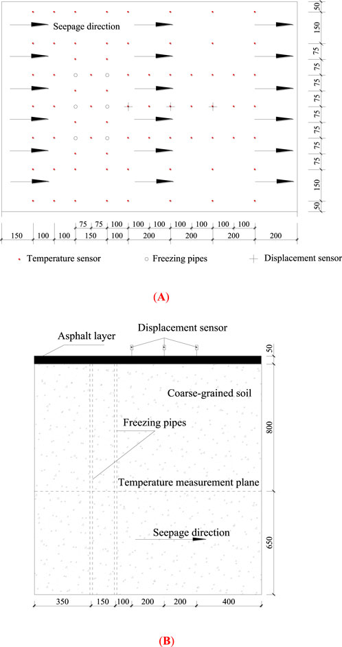
Figure 1. Schematic diagram of the model test. (A) Vertical view. (B) Front view.
3.2 Comparison validation
Based on the monitoring data of two feature points of the artificial freezing multi-field coupling test (Qi et al., 2022), the comparison results are shown in Figures 2, 3 (it should be noted that the numerical calculation also considers the material parameters as constants). The freezing front is the farthest distance from the center of the frozen pipe to the 0°C contour line along the flow direction.

Figure 2. Curve of frozen front radius with freezing time at a seepage velocity of 3.7 m/d.
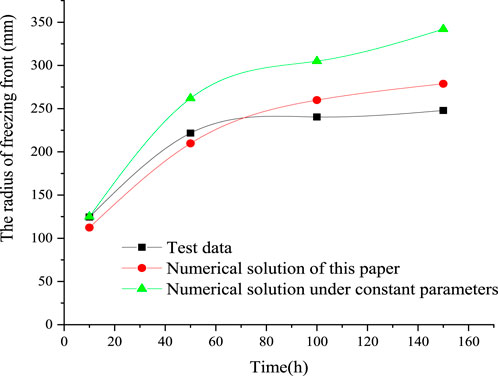
Figure 3. Curve of frozen front radius with freezing time at a seepage velocity of 7.4 m/d.
From the evolution characteristic curves of the freezing front radius over time in Figures 2, 3, it can be observed that both the numerical and experimental results exhibit consistent trends. Notably, at a seepage velocity of 7.4 m/d, the numerical solutions presented in this study demonstrate a higher degree of agreement with the experimental data. Further calculations reveal that in Figure 2, the goodness of fit (R2) for the proposed method is 0.988, while the R2 value for the numerical solution using constant parameters is 0.965. Similarly, in Figure 3, the R2 value for the proposed method is 0.937, whereas the R2 for the constant parameter case is significantly lower at 0.456. These findings indicate that considering key physical parameters (such as viscosity, density, and porosity) as functions of temperature and pressure in numerical simulations significantly enhances the reliability and accuracy of the computed results.
4 Case study
4.1 Scheme setting and parameter selection
A two-dimensional plane model is adopted to conduct a numerical analysis of the artificial freezing process. To eliminate the influence of boundary conditions (Salvatore, 2021; Li et al., 2023; Yan and Jiao, 2019), several numerical tests indicate that the length of the geometric dimension of the plane model can be taken as 4,200 mm and the width as 2000 mm. Subsequently, the freezing processes of a single freezing pipe and double freezing pipes (both with a radius of 30 mm) are analyzed (the physical model is shown in Figure 4). Figure 4A shows the freezing process of a single pipe, and Figure 4B shows the freezing process of double pipes. The seepage direction in both cases is from right to left. The seepage velocities in the numerical tests are 3 m/d, 6 m/d and 9 m/d, respectively. To analyze the influence of the initial temperatures of different soils, the values are set as 20°C, 15°C, and 10°C, respectively. To explore the influence of the freezing temperature, the refrigerant temperatures are set as −30°C, - 25°C, and - 20°C, respectively. In addition, the key material parameters are shown in Table 1.
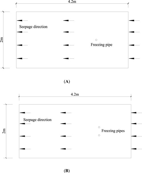
Figure 4. Schematic diagram of single and double pipe modeling. (A) Schematic diagram of a single pipe. (B) Schematic diagram of two pipes.

Table 1. Material parameters.
4.2 Discussion and analysis
4.2.1 Radius of freezing front under different seepage velocity
Figure 5 illustrates the evolution of the freezing front under different seepage velocities for both single-pipe and double-pipe freezing scenarios. It can be observed that the freezing front radius gradually increases over time. In the single-pipe freezing case, the growth rate of the freezing front radius is initially rapid and then gradually decreases until stabilization. Additionally, regardless of whether single-pipe or double-pipe freezing is employed, a higher seepage velocity results in a larger freezing front radius at any given time. This phenomenon occurs because an increased seepage velocity enhances the convective heat transfer effect, causing the cold energy generated by the freezing pipe to be carried downstream by the water flow. Consequently, the 0°C isotherm continuously shifts downward, leading to an expansion of the freezing front radius. However, when the seepage velocity reaches a critical threshold (numerical calculations indicate approximately 16 m/d), soil freezing becomes significantly hindered. Even with a substantial reduction in refrigerant temperature (as low as −50°C), only localized freezing occurs around the surface of the freezing pipe.
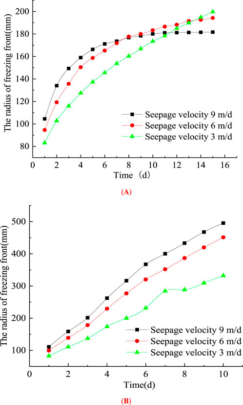
Figure 5. Evolution characteristics of the freezing front under different seepage velocities. (A) Single freezing pipe. (B) Double freezing pipe.
4.2.2 Radius of freezing front at different freezing temperatures
Figure 6 presents the evolution of the freezing front under different refrigerant temperatures for both single-pipe and double-pipe freezing scenarios. It can be observed that, in both cases, the freezing front radius gradually increases over time. For the single-pipe freezing condition, the growth rate of the freezing front radius is initially rapid but gradually decreases. However, in the double-pipe freezing scenario, the freezing front radius exhibits an almost linear growth trend within the computational time span, with a steeper slope observed at lower refrigerant temperatures. These results indicate that lower refrigerant temperatures enhance the freezing effect, and increasing the number of freezing pipes significantly amplifies the freezing efficiency.
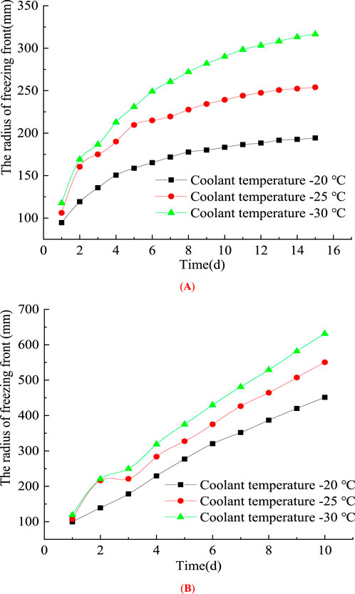
Figure 6. Evolution characteristics of the freezing front at different freezing temperatures. (A) Single freezing pipe. (B) Double freezing pipe.
4.2.3 Radius of freezing front at different initial temperatures of soil
Figure 7 illustrates the evolution of the freezing front under different initial soil temperatures for both single-pipe and double-pipe freezing scenarios. It is evident that the freezing front radius gradually increases over time. In the early stages of freezing, the freezing front curves are nearly identical regardless of the initial soil temperature, for both single-pipe and double-pipe freezing conditions. Furthermore, in the later stages of freezing, the difference in freezing front curves remains insignificant in the double-pipe scenario. A higher initial soil temperature results in a smaller freezing front radius at the same time step. This phenomenon occurs because, when the initial soil temperature is lower, more cooling energy from the freezing pipes is transported downstream with the water flow, leading to an increased freezing front radius.
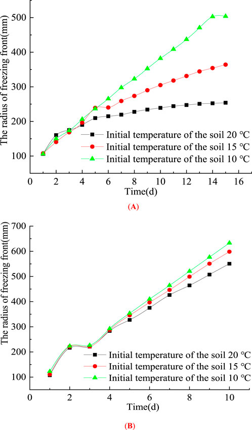
Figure 7. Curve of the radius of the frozen front with freezing time at different initial soil temperatures. (A) Single freezing pipe. (B) Double freezing pipe.
4.2.4 Evolution characteristics of freezing front radius difference under different working conditions
To investigate the temporal evolution of soil freezing effectiveness under different operating conditions, the variation characteristics of the freezing front radius difference can be analyzed under varying conditions of seepage velocity, initial soil temperature, and temperature gradient between the freezing soil and surrounding environment.
In Figures 8, 9, the results of single-pipe and double-pipe freezing conditions are presented, respectively. It can be observed that, regardless of whether single-pipe or double-pipe freezing is applied, the freezing front radius difference under the reduction from 9→6 m/d is consistently larger than that under 6→3 m/d, despite having the same decrement in seepage velocity. This indicates that higher seepage velocities (below a certain threshold) enhance convective heat transfer, allowing more cold energy to be transported downstream with the water flow, thereby facilitating freezing in downstream regions. Additionally, under single-pipe freezing, the freezing front radius difference initially increases and then decreases, whereas under double-pipe freezing, the overall trend of the freezing front radius difference continues to increase.
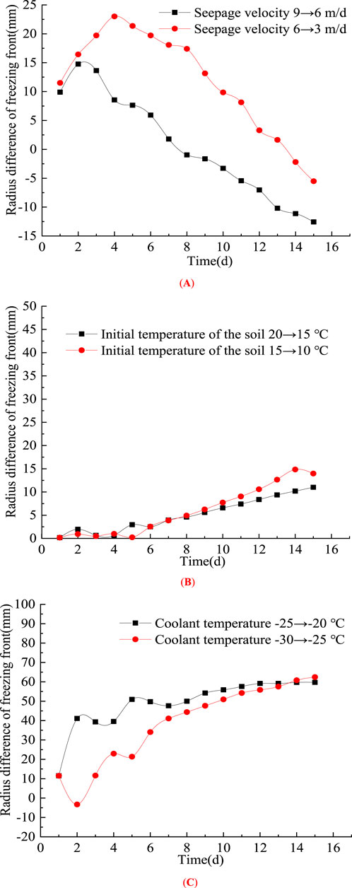
Figure 8. The evolution characteristics of the difference in the freezing front radius under the change of the grade difference of the influencing factors of single - pipe freezing. (A) Seepage velocity. (B) Initial temperature of the soil. (C) Freezing temperature.
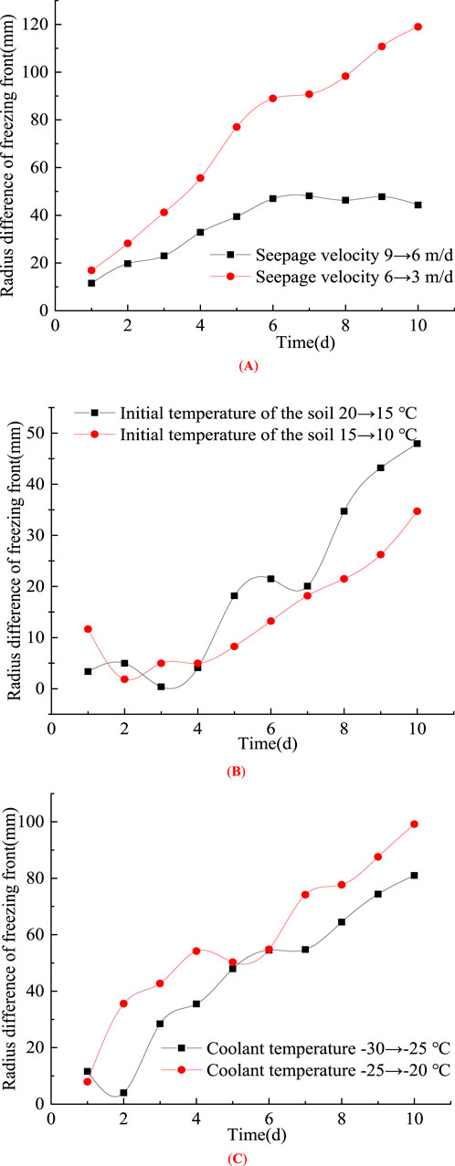
Figure 9. Evolution characteristics of the difference in freezing front radii under the variation of the grade differences of influencing factors during double - pipe freezing. (A) Seepage velocity. (B) Initial temperature of the soil. (C) Freezing temperature.
Under the same variation gradient of the initial soil temperature, the freezing front radius difference exhibits an overall increasing trend for both single-pipe and double-pipe freezing. In the case of single-pipe freezing, the two curves are nearly identical, while in double-pipe freezing, the difference in the initial soil temperature gradient is more pronounced. Similarly, when the temperature gradient of the freezing coolant changes, the freezing front radius difference continues to increase for both single-pipe and double-pipe freezing.
4.2.5 The change of pore pressure during freezing process
Figure 10 illustrates the temporal evolution of pore pressure at two characteristic points in the unfrozen downstream region under double-pipe freezing conditions. It can be observed that pore pressure gradually increases over time. At locations closer to the freezing pipes, the pore pressure rises rapidly in the early stage and slows down later, whereas at points farther from the freezing pipes, the pore pressure exhibits an approximately linear increase throughout the computational time span. This phenomenon occurs due to the volumetric expansion of the frozen region, which forces water migration from the frozen zone to the unfrozen area, leading to a progressive increase in pore water pressure in the unfrozen region.
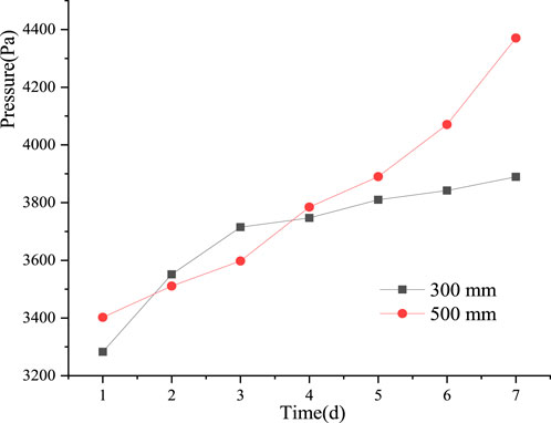
Figure 10. The variation of pore pressure with time at characteristic points.
5 Conclusion
Considering the effects of temperature and pressure, functions for fluid and solid density, viscosity, and porosity are established. Based on Darcy’s law, as well as the principles of mass conservation, momentum conservation, and energy conservation, a thermo-hydro-mechanical coupling theoretical model incorporating seepage effects is derived. A finite element platform is further developed to achieve numerical modeling of the artificial freezing process under seepage conditions, followed by experimental validation. Subsequently, numerical simulations are conducted to analyze the influence of different operating conditions. The main conclusions are as follows.
(1) As the seepage velocity increases (below a certain threshold), the frozen front radius of the soil under identical freezing conditions becomes larger. This is attributed to the convective heat transfer effect, where the cold energy generated by the freezing pipes is transported more rapidly through the soil, promoting the expansion of the frozen front.
(2) A greater number of freezing pipes leads to a more pronounced freezing effect. Lower refrigerant temperatures result in a larger frozen radius under the same freezing conditions. Additionally, lower initial soil temperatures enhance the freezing effect within the same freezing duration.
(3) Under decreasing gradient conditions, the difference in the frozen front between 9→6 m/d is consistently greater than that between 6→3 m/d. Moreover, with variations in both initial soil temperature and refrigerant temperature gradient, the frozen front radius difference exhibits an overall increasing trend, regardless of whether single-pipe or double-pipe freezing is applied.
Data availability statement
The original contributions presented in the study are included in the article/supplementary material, further inquiries can be directed to the corresponding author.
Author contributions
PC: Conceptualization, Funding acquisition, Methodology, Project administration, Supervision, Writing – original draft. FY: Validation, Writing – review and editing. MW: Software, Validation, Writing – review and editing.
Funding
The author(s) declare that financial support was received for the research and/or publication of this article. National Natural Science Foundation of China (51808026); BUCEA Post Graduate Innovation Project (PG2025062).
Conflict of interest
The authors declare that the research was conducted in the absence of any commercial or financial relationships that could be construed as a potential conflict of interest.
Generative AI statement
The author(s) declare that no Generative AI was used in the creation of this manuscript.
Publisher’s note
All claims expressed in this article are solely those of the authors and do not necessarily represent those of their affiliated organizations, or those of the publisher, the editors and the reviewers. Any product that may be evaluated in this article, or claim that may be made by its manufacturer, is not guaranteed or endorsed by the publisher.
References
Bai, B., Bai, F., Li, X. K., Nie, Q. K., Jia, X. X., and Wu, H. Y. (2022). The remediation efficiency of heavy metal pollutants in water by industrial red mud particle waste. Environ. Technol. and Innovation. 28, 102944. doi:10.1016/j.eti.2022.102944
Bai, B., Wu, H. Y., Nie, Q. K., Liu, J. J., and Jia, X. X. (2025). Granular thermodynamic migration model suitable for high-alkalinity red mud filtrates and test verification. Int. J. Numer. Anal. Methods Geomechanics 49, 1530–1543. doi:10.1002/nag.3946
Bai, B., Zhou, R., Yang, G., Zhou, W. L., and Yuan, W. (2023). The constitutive behavior and dissociation effect of hydrate-bearing sediment within a granular thermodynamic framework. Ocean. Eng. 268, 113408. doi:10.1016/j.oceaneng.2022.113408
Chen, C., Zhang, Z. G., Ling, L., He, B. Y., Jiang, Y. J., and Cheng, Z. H. (2022). Frost heaving properties of gravelly soils in alpine seasonally frozen regions. Adv. Mater. Sci. Eng. 2022, 1–11. doi:10.1155/2022/5249999
Cheng, H., Wang, B., Zhao, J. L., Yao, Z. S., and Rong, C. X. (2021). Causes for frozen wall gap in water-rich sand pebble formation and its closing technology. Meikuang Anquan 53 (10), 1–8. doi:10.11799/ce202110001
Guo, S. D., Wang, X. C., Zhang, Y. Y., and Chen, Z. M. (2024). Research on optimization of insulation layer thickness for permafrost tunnels based on hydro-thermal coupling model. J. Water Resour. Water Eng. 35 (02), 192–200. doi:10.11705/i.issn.1672-643X.2024.02.22
Harlan, R. L. (1973). Analysis of coupled heat-fluid transport in partially frozen soil. Water Resour. Res. 9, 1314–1323. doi:10.1029/WR009i005p01314
Hu, G. J., Zhao, L., Li, R., Park, H., Wu, X. D., Su, Y. Q., et al. (2023). Water and heat cou pling processes and its simulation in frozen soils: current status and future research directions. CATENA 222 (Suppl. C), 106844. doi:10.1016/j.catena.2022.106844
Hu, R., Liu, Q., and Xing, Y. X. (2018). Case study of heat transfer during artificial ground freezing with groundwater flow. Water 10, 1322. doi:10.3390/w10101322
Kong, X. Y., Li, D. L., Xu, X. Z., and Lu, D. T. (2005). Study on the mathematical model of thermal-fluid-solid coupling seepage. Hydrodynamic Res. Prog., 269–275. doi:10.3969/j.issn.1000-4874.2005.02.020
Lai, Y. M., Liu, S. Y., Wu, Z. W., Wu, Y. P., and Konrad, J. M. (2002). Numerical simulation for the coupled problem of temperature and seepage fields in cold region dams. J. Hydraulic Res. 40, 631–635. doi:10.1080/00221680209499907
Lai, Y. M., Wu, Z. W., Zhu, Y. L., and Zhu, L. N. (1999). Nonlinear analyses for the coupled problem of temperature, seepage and stress fields in cold region tunnels. Chin. J. Geotechnical Eng. 21, 529–533. doi:10.1016/S0886-7798(98)00086-8
Li, H. B., Li, S., Kang, X. R., Wu, L. B., and Ding, Y. F. (2023). Understanding unsaturated sulfate saline soil in cold regions: a comprehensive hydraulic–thermal–air–salt–mechanical model with experimental research. Cold Regions Sci. Technol. 215, 103970. doi:10.1016/j.coldregions.2023.103970
Li, P. C., Kong, X. Y., and Lu, D. T. (2003). Mathematical model of fluid - solid coupled seepage in saturated porous media. J. Hydrodynamics (04), 419–426. doi:10.3969/j.issn.1000-4874.2003.04.006
Liu, S., Li, X. K., Li, X., Nie, W., Lin, Y., and Sheng, Z. G. (2024). Exploration of the intersection law and prediction model of the frozen wall of coarse - grained soil under seepage action. J. Glaciol. Geocryol. 46 (01), 247–259. doi:10.7522/i.issn.1000-0240.2024.0021
Pan, X. D., Bai, Y. L., Bai, Y. F., Zhang, Z. Q., and Liao, L. (2021). Study on the influence pattern of seepage field on temperature field in the construction of the metro cross passage by freezing method in water-rich strata. Mod. Tunn. Technol. 58 (5), 122–128. doi:10.13807/j.cnki.mtt.2021.05.015
Qi, J. L., Wang, F. Y., Peng, L. Y., Qu, Y., Zhao, J. L., and Liang, J. Y. (2022). Model test on the development of thermal regime and frost heave of a gravelly soil under seepage during artificial freezing. Cold Regions Sci. and Technol. 196, 103495. doi:10.1016/j.coldregions.2022.103495
Rong, C. X., Zhang, X., Cheng, H., Wang, B., and Lin, J. (2018). Experimental study on influence of groundwater velocity on freezing temperature field. Joumal Guangxi Univ. Sci. Ed. 43, 656–664. doi:10.13624/j.cnki.issn.1001-7445.2018.0656
Rui, D. H., Zhai, J. B., Li, G. Y., Zhang, J., and Suzuki, T. (2019). Field experimental study of the characteristics of heat and water transfer during frost heaving. Cold Regions Sci. Technol. 168, 102892. doi:10.1016/j.coldregions.2019.102892
Salvatore, V. (2021). Effect of different environments’ conditioning on the debonding phenomenon in fiber-reinforced cementitious matrix-concrete joints. Materials 14 (24), 7566. doi:10.3390/ma14247566
Shen, L. F., Wang, Z. L., Li, T. F., and Meng, H. B. (2023). Research on the hydro - thermal coupling mechanism during the horizontal freezing process of unsaturated soil. J. China Railw. Soc. 45 (10), 135–143. doi:10.3969/i.issn.1001-8360.2023.10.016
Vitel, M., Rouabhi, A., Tijani, M., and Guérin, F. (2016a). Modeling heat and mass transfer during ground freezing subjected to high seepage velocities. Comput. Geotechnics 73, 1–15. doi:10.1016/j.compgeo.2015.11.014
Vitel, M., Rouabhi, A., Tijani, M., and Guérin, F. (2016b). Thermo-hydraulic modeling of artificial ground freezing: application to an underground mine in fractured sandstone. Comput. Geotechnics 75, 80–92. doi:10.1016/j.compgeo.2016.01.024
Wang, S. R., Jin, X. W., Chen, S. J., Lu, Q. R., Zhang, M. S., and Xie, S. J. (2024). Freezing swelling characteristics of strata reinforced by the combined construction method of cement pre - reinforcement and artificial freezing. Sci. Technol. Eng. 24 (13), 5566–5576. doi:10.12404/i.issn.1671-1815.2302729
Yan, C. Z., and Jiao, Y. Y. (2019). FDEM-TH3D: a three-dimensional coupled hydrothermal model for fractured rock. Int. J. Numer. Anal. Methods Geomechanics 43 (1), 415–440. doi:10.1002/nag.2869
Yang, X., Ji, Z., Zhang, P., and Qi, J. L. (2019). Model test and numerical simulation on the development of artificially freezing wall in sandy layers considering water seepage. Transp. Geotech. 21, 100293. doi:10.1016/j.trgeo.2019.100293
Zhang, J. M., Chu, X. H., and Yu, M. (2025). Hydro - thermal - mechanical coupling model of peridynamics and simulation of concrete freezing damage. Eng. Mech. doi:10.6052/j.issn.1000-4750.2023.11.0828
Keywords: seepage velocity, artificial freezing, thermo-hydro-mechanical coupling, experimental verification, numerical simulation
Citation: Chen P, Yin F and Wang M (2025) Analysis of thermo-hydro-mechanical coupling characteristics of artificial freezing process under seepage effects. Front. Mater. 12:1600337. doi: 10.3389/fmats.2025.1600337
Received: 26 March 2025; Accepted: 21 April 2025;
Published: 14 May 2025.
Edited by:
Wenbing Wu, China University of Geosciences Wuhan, ChinaReviewed by:
Salvatore Verre, University of eCampus, ItalyHongliang Tu, Chinese Academy of Sciences (CAS), China
Copyright © 2025 Chen, Yin and Wang. This is an open-access article distributed under the terms of the Creative Commons Attribution License (CC BY). The use, distribution or reproduction in other forums is permitted, provided the original author(s) and the copyright owner(s) are credited and that the original publication in this journal is cited, in accordance with accepted academic practice. No use, distribution or reproduction is permitted which does not comply with these terms.
*Correspondence: Peipei Chen, Y2hlbnBlaXBlaUBidWNlYS5lZHUuY24=