 Sandip Mane
 Rajkumar Bhimgonda Patil1
 Md Irfanul Haque Siddiqui
 Choon Kit Chan
 Yong Xu
- 1Department of Mechanical Engineering, Dwarkadas J. Sanghvi Engineering College, Mumbai, Maharashtra, India
- 2Department of Mechanical Engineering, College of Engineering, King Saud University, Riyadh, Saudi Arabia
- 3Department of Mechanical Engineering, INTI International University, Nilai, Malaysia
- 4School of Artificial Intelligence and Smart Manufacturing, Hechi University, Yizhou, China
Hard turning is a high-precision machining approach widely adopted in manufacturing for finishing hardened alloy steels that exhibit superior hardness and excellent wear resistance. The residual stresses induced during the hard turning process significantly impact the performance and reliability of the machined component. This study presents a comprehensive finite element analysis to predict residual stress distribution and thermal behavior during dry hard turning of AISI 52100 steel under varying cutting conditions. The Power Law material model, incorporating a strain hardening function, was employed to simulate the material’s behavior at high strain rates, accounting for strain rate sensitivity and thermal softening due to elevated temperatures during machining. The model further includes a Coulomb friction approach to capture the interactions between the tool, chip, and workpiece. The cutting speed was found to have the most significant impact on surface tensile stresses. The subsurface residual stresses were greatly affected by the feed rate. The elevated feed rates resulted in increased compressive residual stresses being induced in the machined component. The developed FEM model demonstrated its effectiveness as an essential tool for pre-processing residual stress predictions, which in turn helps in the design and manufacture of reliable, high-quality, components. The thermal performance of coated carbide tools; more specifically, the performance of titanium nitride (TiN), titanium carbonitride (TiCN), and aluminum oxide (Al2O3) coating layers were examined. Tools coated with multilayer structures incorporating Al2O3 as the top layer demonstrated superior thermal barrier performance, leading to a notable reduction in both heat generation and maximum cutting temperatures. The cutting temperature data recorded using embedded thermocouple technique with infrared thermometers showed a good agreement with the FEM results. This validation confirms the AdvantEdge’s simulation precision and enhances understanding of machining dynamics, contributing to robust component design with superior surface integrity.
1 Introduction
Machining hardened materials using hard turning has gradually emerged as a viable alternative to conventional grinding, owing to its efficiency and cost-effectiveness. It offers several advantages, including reduced setup times, improved process efficiency, shorter cycle times, and lower costs. However, the high thermo-mechanical loads involved in this high-strain-rate material removal process result in elevated cutting temperatures and induce complex residual stress distributions, which significantly influence the machined surface properties such as surface integrity, fatigue life, and dimensional stability. These residual stresses play a crucial role in determining the structural integrity and service performance of components, especially under dynamic loading conditions. The residual stress formation during machining of hard-to-cut material is a crucial area of research where the interest in the prediction of these stresses and understanding their origins and mitigating their adverse effects is increasing. The research shifted its focus from measuring post-process residual stresses to developing methods for predicting pre-process residual stresses through numerical simulations using finite element method (FEM). Tool coatings significantly influence temperature distribution within the cutting zone by acting as thermal barriers that reduce heat conduction into the tool substrate. Coatings such as TiN, TiCN, TiAlN or Al2O3 exhibit low thermal conductivity and high oxidation resistance, effectively confining heat to the chip and reducing thermal load on the cutting edge. This localized heat management not only delays tool wear but also stabilizes cutting temperatures, leading to improved surface integrity and process consistency during dry hard turning of hardened steels. In this context, specialized simulation platforms are widely used for stress analysis, facilitating a comprehensive understanding of thermo-mechanical interactions during the metal-cutting process. The experimental and empirical studies examined the influence of process parameters, such as feed rate, depth of cut, and tool geometry on residual stress states in precision hard turning. Table 1 presents the literature review of residual stress formation, tool coatings, thermal effects, and simulation approaches.
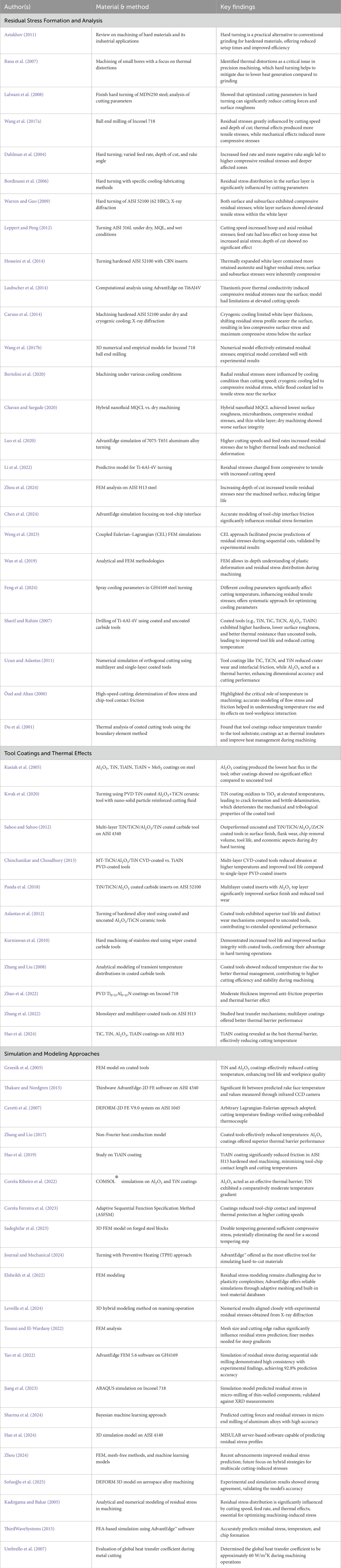
Table 1. Review of residual stress formation, tool coatings, thermal effects, and simulation approaches.
Modeling the machining process with FEM-based simulation offers valuable insights into process dynamics. DEFORM and AdvantEdge are simulation platforms with extensive modeling capabilities and can integrate material properties, tool geometries, and process parameters. AdvantEdge provides the best predictions compared to several other software within the cutting conditions used. However, the combined influence of cutting speed, feed rate, and depth of cut on residual stress formation in dry hard turning requires further exploration. Additional research is needed to understand how these parameters interact when subjected to increased mechanical and thermal stresses during dry machining, as they do affect stress distribution. Heat dissipation is greatly influenced by tool coatings such as TiN, TiCN, and Al2O3, although the effect of coating material and thickness on thermal performance is not well demonstrated and the stated results in the literature are inconsistent and contradictory. The objectives of this research are as below:
• To develop a FEM-based predictive model for pre-process residual stress prediction and tool coating selection to achieve improved machining performance in dry hard turning.
• To analyze the influence of cutting parameters: cutting speed, feed rate, and depth of cut on residual stresses induced during dry hard turning using Finite Element Method (FEM).
• To study the effect of different coating materials on temperature distribution and heat rate in the cutting zone.
2 Materials and methods
Finite element analysis is an essential and integral tool for the simulation of machining processes. These methods facilitate the analysis of the metal cutting process with all its difficulties in terms of fracture mechanics, heat transfer, performance in the plastic and elastic state of a material, metallurgy, and the effect of using coolants. The finite element method (FEM) based commercial software ‘AdvantEdge’ was used in this study for process simulation and analysis. AdvantEdge is an explicit dynamic Lagrangian code capable of conducting conjugate thermo-mechanical transient analysis. This software uses an adaptive meshing for both chips and workpieces, that ensure accurate results. It has an extensive database of workpieces and tool materials that are typically used in cutting operations and provide all the data necessary for efficient material modeling. The workpiece material, cutting tools, and process settings were modeled from the software menu and data library. Cutting parameter combinations were chosen based on practical machining conditions, prior research, and industry relevance. This systematic selection provides a comprehensive analysis of residual stress distribution and temperature behavior in dry hard turning, ensuring direct applicability to real-world machining. This research gap highlights the importance of the development of accurate FEM models that incorporate complex heat transfer mechanisms and investigate the combined influence of cutting parameters on residual stresses and thermal performance in the hard turning process. Figure 1 presents the possible simulation output of AdvantEdge Software.
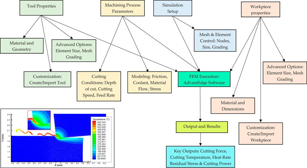
Figure 1. Possible AdvantEdge simulation output.
2.1 Material constitutive model and friction model
The material model is a crucial aspect of finite element simulation, significantly influencing the accuracy of the results. To ensure precise simulations, the Power Law material model was selected to conduct the simulation. It comprises a strain hardening function, denoted as g
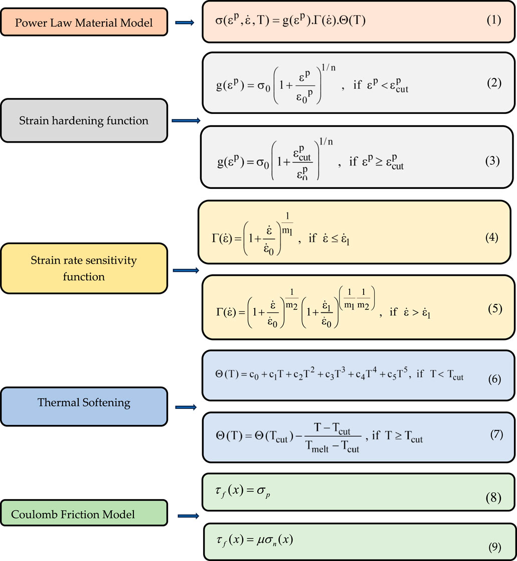
Figure 2. Material constitutive model and friction model.
The material constitutive model governed by the Power Law is illustrated in Figure 1. During metal cutting processes, the material undergoes deformation in both the primary and secondary cutting zones. This deformation takes place at high temperatures and involves extremely high stresses and strain rates (ranging from 105 to 107 s−1). Conversely, the rest of the workpiece undergoes deformation at moderate or even modest rates of strain. The strain hardening function g
Thermo-mechanical properties substantially affect the parameters of constitutive models in AdvantEdge machining simulation. The basic option offers a predefined material library, whereas the custom option enables users to select specific properties. AdvantEdge automatically integrates these properties into its constitutive models, which govern strain hardening, strain rate sensitivity, and thermal softening. Table 2 delineates the thermo-mechanical properties of tool workpiece materials.
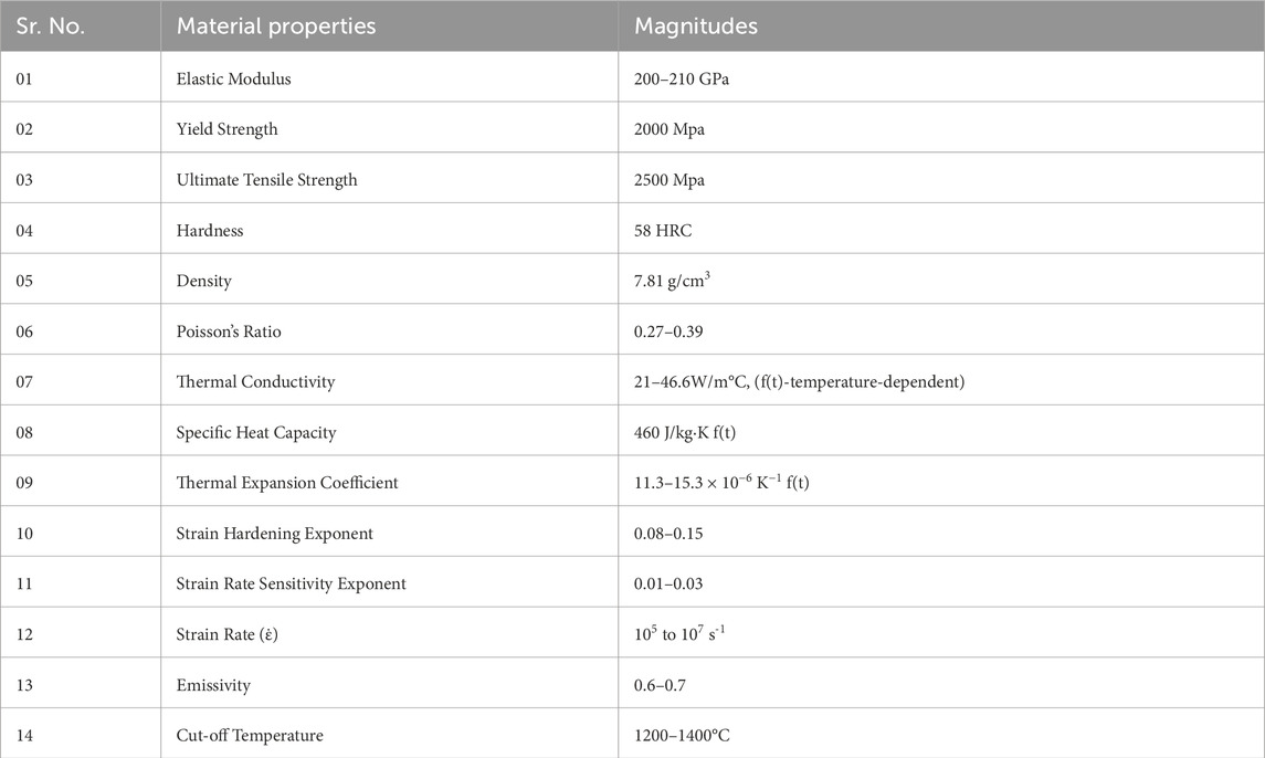
Table 2. Thermo-mechanical properties AISI 52100 alloy steel (58 HRC).
2.2 Tool modeling
The WC-Co sintered carbide tool coated with three layers (TiN/TiCN/Al2O3) coating was modeled. Tool coating within AdvantEdge was done using a thin layer of an explicitly meshed coating. Three layers of coating Al2O3: 5 μm, TiCN: 3 µm and TiN: 2 µm were selected to leverage the distinct benefits of each coating material based on previous studies, simulation trials, and experimental measurements of cutting temperature. The 2 µm TiN layer, positioned as the innermost coating, provides robust adhesion to the carbide substrate while ensuring excellent wear resistance. The 3 µm TiCN intermediate layer enhances the tool’s hardness and fracture toughness, serving as a transitional phase to absorb mechanical stresses between the ductile inner TiN and the outer Al2O3 layer. The 5 µm Al2O3 layer, as the outermost coating, acts as a strong thermal insulator, preventing oxidation and maintaining tool integrity under high temperature cutting conditions. This combination of coatings ensures optimal performance and durability for hard turning applications. The tetrahedral-type mesh was used for the meshing process. A total of 24,000 nodes were applied for mesh generation, with a mesh grade of 0.4 and element sizes of 0.05 mm and 0.01 mm respectively.
For accurate predictions, temperature-dependent thermal conductivity values were used. The thermal conductivity of the multi-layer coated carbide tool exhibits considerable variation as a result of its layered structure. The coating materials, including TiN, TiCN, and Al2O3, demonstrate low thermal conductivity (7–33 W/m·K), functioning as thermal barriers that diminish heat dissipation into the tool. The tungsten carbide substrate exhibits notably higher thermal conductivity (30–47.50 W/m·K), facilitating effective heat dissipation from the cutting zone. Interactions between the tool and workpiece, as well as the tool and chip, were modelled with friction coefficients ranging from μ = 0.5 to 0.7 for hard turning. The heat partitioning ratios were established as follows: 80%–85% of heat was directed into the chip, 10%–15% into the workpiece, and 3%–7% into the tool. The thermal properties were incorporated according to established literature to ensure precise FEM-based thermal modelling and realistic temperature distribution in the simulation. Table 3 presents mechanical and thermal properties of coated and uncoated materials.
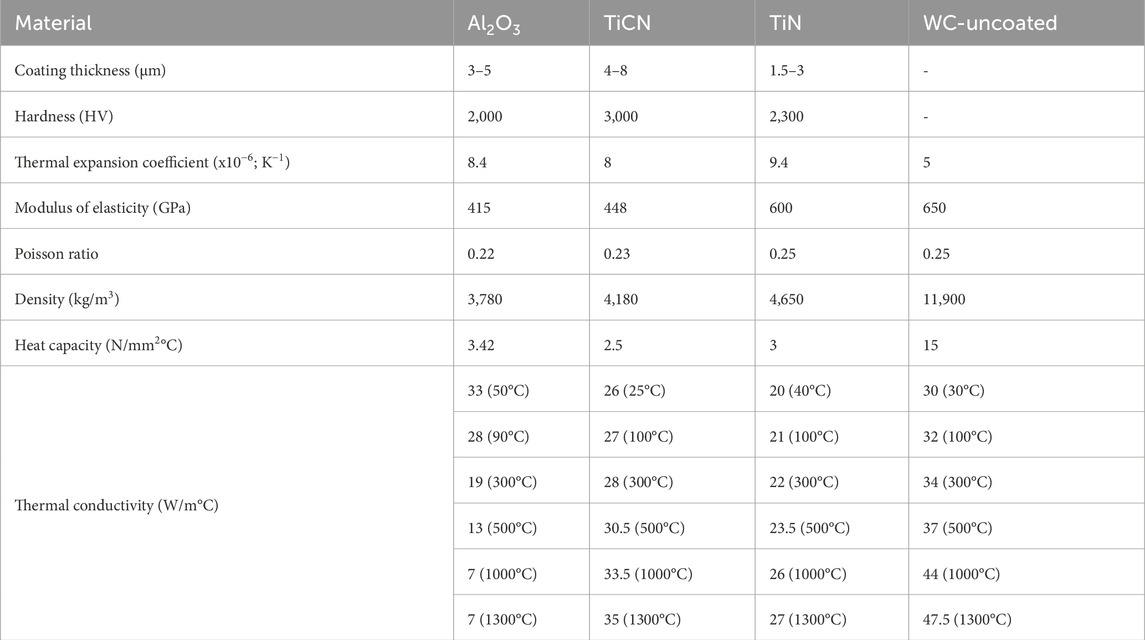
Table 3. Thermo-mechanical properties of coating materials.
Figure 3 illustrates the turning simulation interface, allowing users to define workpiece dimensions and simulate machining process. Initial stress conditions can be adjusted through external file input for customized simulation configurations. A stress-free initial state assumption was adopted to ensure accurate thermal and mechanical behavior representation, with the interface offering a clear visual of the process for detailed analysis.

Figure 3. Schematic representation of turning process in 2D and turning process parameters.
2.3 Mesh refinement
ThirdWave AdvantEdge employed a Lagrangian framework enhanced with adaptive mesh strategies to accurately track material deformation. Mesh behavior was controlled using two critical parameters: the coarsening factor, which regulated mesh expansion following large deformations, and the refinement factor, which ensured localized mesh precision. The meshing parameters for the workpiece were optimized to balance resolution and computational efficiency. The mesh featured a maximum element size of 0.1 mm and a minimum of 0.02 mm, with a mesh grading of 0.4 to ensure smooth size transitions. A curvature-safety factor of 1.5 was applied to capture complex geometries with fidelity, and edge discretization was refined using a setting of 0.5 segments per edge to enhance boundary accuracy. Figure 4 illustrates the meshing configuration adopted for the workpiece and cutting tool.
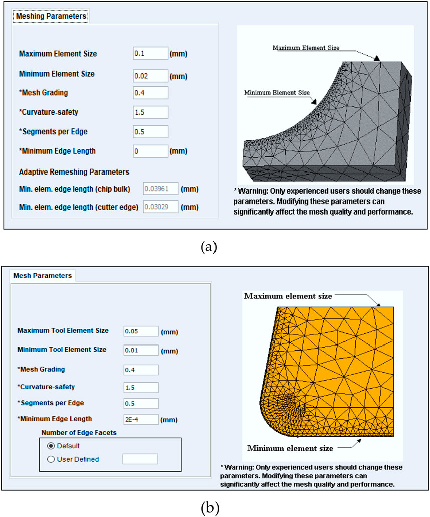
Figure 4. (a) Workpiece meshing parameters (b) Cutting tool meshing parameters.
The meshing configuration adopted for the cutting tool was designed with optimized element resolution to balance accuracy and computational efficiency. The mesh featured a finest element size of 0.01 mm and a coarsest size of 0.05 mm. A mesh grading value of 0.4 was used to manage the transition between element sizes, while a curvature safety factor of 1.5 ensured the geometry’s curved features were accurately captured. The edge discretization parameter was set to 6 segments per edge, and the minimum edge length was defined as 0.24 mm. Coarser mesh zones were applied to geometrically simpler regions, whereas finer meshes were allocated near critical zones to improve simulation fidelity without excessive computational load.
2.4 Friction model
The AdvantEdge simulation framework employs a classical Coulomb-based sliding friction model to characterize tool–chip interface behavior. This approach assumes a constant coefficient of friction (μ), where the frictional force scales linearly with the normal contact force. The total tool–chip contact length integrates both adhesive and sliding zones, enabling accurate prediction of interface stresses and heat generation during machining. This interaction model is represented in Figure 2. This study adopted a coefficient of friction (COF) value of 0.6, consistent with established tribological behavior and thermomechanical conditions. This choice aligns with validated numerical modeling techniques and ensures realistic predictions of cutting forces, cutting temperatures, and temperature distributions.
2.5 Experimental method
The experimental trials were conducted using an HMT NH-18 high-precision lathe, a machine well-regarded for its operational stability and consistent performance in precision turning applications.
2.5.1 Test specimen and its chemical composition
AISI 52100, a high-carbon, chromium-containing low-alloy steel, is extensively utilized in critical engineering applications such as aircraft bearing components, precision ball and roller bearings, CV joints, spinning tools, gauges, punches, dies, and ball screws. Its selection as the workpiece material in this study was driven by its prevalent use in automotive and precision manufacturing sectors. The received specimens exhibited a hardness of approximately 20 HRC. To validate the material’s chemical composition, spectrometric analysis was conducted using a BRUKER optical emission spectrometer (Model: Q4 TASMAN), and the results were benchmarked against the composition data available in the AdvantEdge material database. The experimentally determined elemental composition closely matched the database entry, justifying the adoption of the standard AISI 52100 material from the simulation library. Utilizing the default material parameters from AdvantEdge enabled realistic modeling of material behavior while maintaining alignment with experimental and published references. Table 4 summarizes the elemental composition of AISI 52100 steel obtained via spectrometry and the corresponding composition from the simulation library.
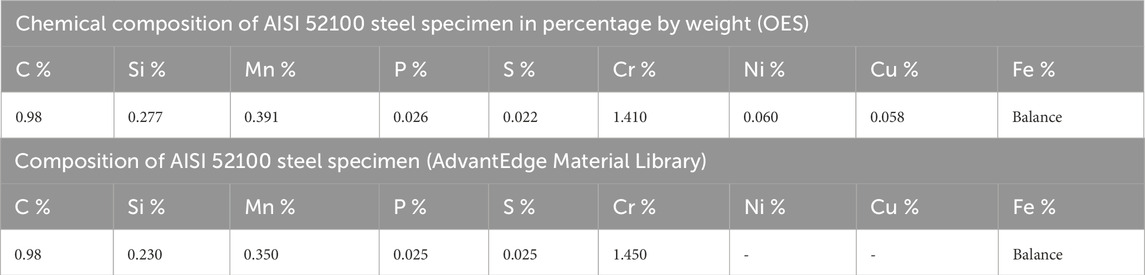
Table 4. Chemical composition of AISI 52100 steel specimen.
2.5.2 Heat treatment of workpiece material
The heat treatment process for the AISI 52100 steel involved austenitizing the bars at 920°C for 30 min, followed by oil quenching to achieve the desired martensitic transformation. Subsequently, tempering was performed by reheating the quenched specimens to approximately 400°C, well below the lower critical temperature, threshold and maintaining this condition for 2 h. The components were then air-cooled to relieve internal stresses and promote microstructural uniformity. This thermal cycle produced a stable and homogeneous metallurgical state, thereby validating the assumption of an initially stress-free condition in the finite element analysis. Post-treatment hardness was measured to be 58 ± 1 HRC, confirming the effectiveness of the heat treatment.
2.5.3 Cutting insert and tool holder
Multilayer-coated carbide inserts present a cost-effective solution for hard turning operations, particularly when compared to more expensive CBN, PCBN, and ceramic tools. In this study, hard turning experiments were performed using HK 150 grade inserts, which feature a multilayer coating structure designed to enhance wear resistance and thermal stability. These inserts were securely mounted on a PCLNR2020 K12 right-hand tool holder to ensure optimal cutting performance and tool alignment. The insert geometry, along with the coating architecture over the carbide substrate, is illustrated in Figure 5.
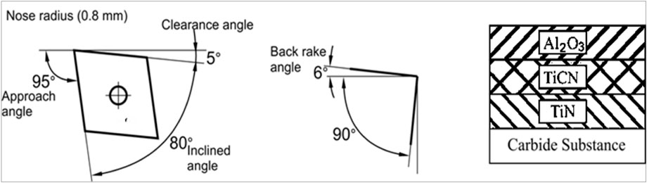
Figure 5. Geometry of cutting inserts and coating layer with carbide substrate.
The detailed tool geometry, including critical angles and dimensional parameters, was meticulously embedded into the finite element model to maintain simulation accuracy and ensure alignment with actual machining configurations. This integration allowed the model to replicate realistic cutting interactions, thereby enhancing the consistency and credibility of the simulation results.
2.5.4 Measurement of cutting temperature
Accurately capturing the temperature at the tool–chip interface in metal cutting remains a complex and demanding task due to the transient and localized nature of heat generation during machining. The intricate thermal gradients and limited accessibility in the cutting zone pose significant difficulties in establishing a reliable measurement system. To address this, the present study employed a combination of an infrared thermometer and an embedded thermocouple technique to record the cutting edge temperature, in alignment with the methodology detailed by Hoyne et al. (2015).
Figure 6 illustrate the experimental setup, featuring the infrared thermometer and the cutting tool embedded with a thermocouple, respectively. The HTC IRX-68 infrared thermometer was used for temperature measurement, offering a wide detection range of −50°C–1850°C via infrared (IR) and −50°C–1370°C via Type K thermocouple, with accuracy margins of ±1.0% for (IR) mode and ±1.5% for (Type K) thermocouple-based readings. Key features include a rapid response time under 150 ms, a high optical resolution of 50:1, and adjustable emissivity spanning from 0.10 to 1.0. Emissivity values for reliable thermal readings were derived from literature and validated experimentally. The tool exhibited emissivity in the range of 0.2–0.4, the chip between 0.5 and 0.8 (due to surface oxidation), and the workpiece between 0.4 and 0.7, depending on thermal and surface conditions. Final emissivity values were set at 0.4 for the tool and 0.6 for the workpiece based on infrared and thermocouple validation. A K-type thermocouple was precisely positioned in blind holes located less than 0.3 mm from the cutting edge, created using EDM perpendicular to the flank face. To minimize structural weakening and ensure optimal proximity (as close as 0.15 mm) to the cutting edge, blind hole dimensions were carefully chosen to preserve insert integrity post-EDM, as shown in Figure 7.
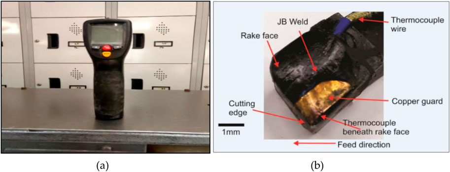
Figure 6. (a) Infrared thermometer (b) Cutting tool with embedded thermocouple.
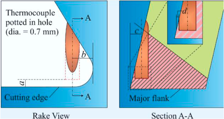
Figure 7. Thermocouple location.
To shield the thermocouple from direct interaction with chip formation during cutting operations, a copper guard was affixed over it using a high-strength metal adhesive, ensuring both thermal protection and mechanical stability. The thermocouple’s integration within the cutting insert was governed by four critical geometric parameters denoted as a, b, c, and d, which collectively defined its spatial positioning to maximize thermal sensitivity while preserving the tool’s mechanical integrity. Parameter a refers to the lateral offset from the cutting edge along the rake face, a dimension selected to enhance thermal responsiveness while safeguarding the thermocouple from mechanical damage. Dimension b corresponds to the vertical depth of the drilled blind hole, oriented perpendicularly to the rake surface, a key factor in determining the thermocouple’s response time and positional rigidity. Parameter c measures the distance between the hole center and the principal flank face, offering flexibility for micro-adjustments in placement while avoiding compromise to tool robustness. The critical dimension d defines the minimal remaining material thickness between the blind hole and the adjacent flank surface, meticulously controlled at 0.15 mm. This ensures a balance between proximity for accurate thermal capture and sufficient residual material to retain insert strength under load. These meticulously defined parameters collectively optimize the thermocouple’s embedment, enabling precise, reliable temperature monitoring during machining. The detailed specifications for each dimension are provided in Table 5, outlining the geometry of the blind holes used in the study.
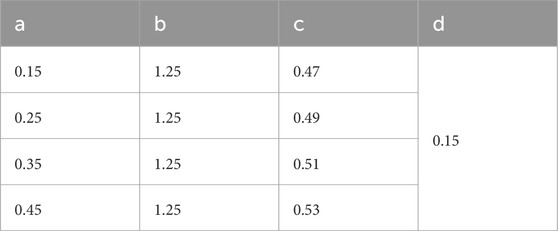
Table 5. Blind hole dimensions on the inserts (mm).
2.6 Residual stress volume averaging
Residual stresses generated during hard turning are caused due to mechanical and thermal influences, resulting in either compressive or tensile stress states on the surface, influenced by cutting parameters and the machining environment. Thermal effects have a completely different effect than mechanical effects. During exposure to intense heat fluxes, a significant temperature gradient causes localized plasticization of the workpiece material. As the surface returns to room temperature, residual tensile stresses remain on the surface accompanied by compressive stresses in the sub-surface.
The residual stress volume averaging feature within AdvantEdge software provides a residual stress prediction that mimics X-ray diffraction test data. Stress over an area is averaged as a function of depth into the workpiece surface. The stress distribution throughout an area is calculated by taking the average stress values at different depths into the surface of the workpiece. The measurement of residual stress was conducted in the circumferential direction (σhoop). The residual stress was graphed in units of stress (MPa) as a function of the distance from the surface of a machined workpiece to the center (mm). The extraction of residual stress can be performed by a single line positioned at the midpoint of the machined surface cut. The extraction was performed by taking the average of three sections (extraction at 25%, 50%, and 75%) of the machined surface. The process includes workpiece modeling, tool modeling, friction modeling, meshing, and boundary conditions. Figure 8 illustrates the lines of residual stress extraction and Thirdwave AdvantEdge model for residual stress. The model parameters were selected based on the similar work carried out by Kadirgama et al. (2012) (Kadirgama and Bakar, 2005) and according to the guidelines given in the Third Wave AdvantEdge, AdvantEdge FEM 7.1 User’s Manual (ThirdWaveSystems, 2015).
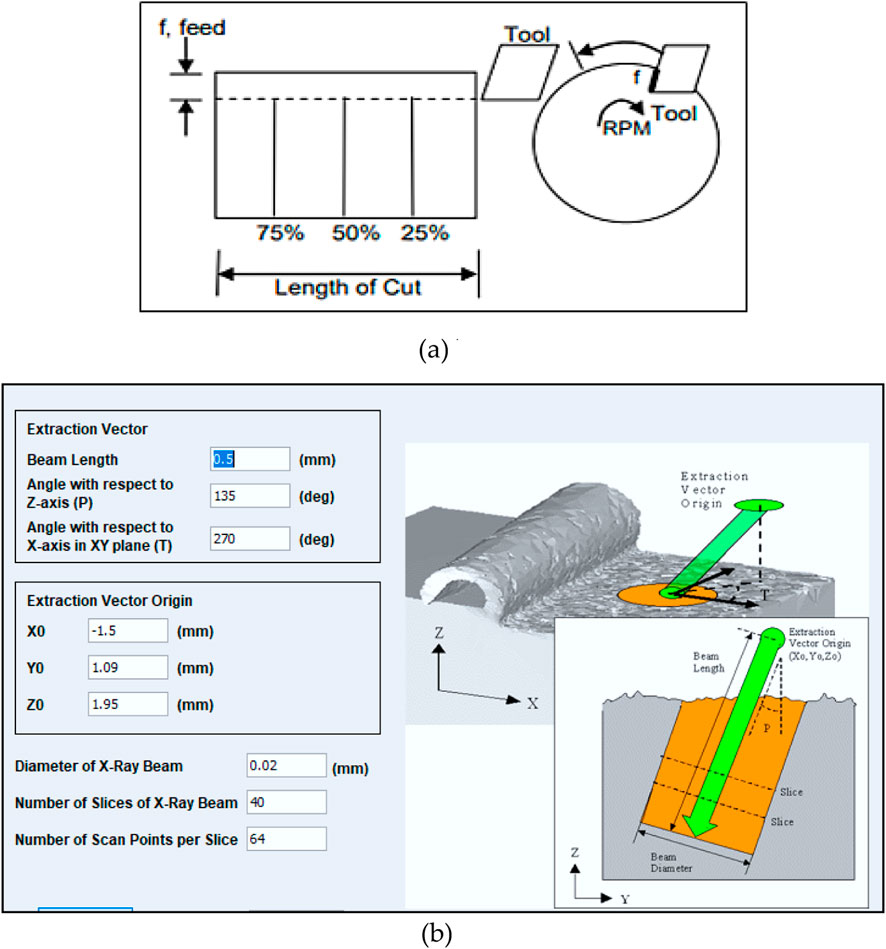
Figure 8. (a) Lines of residual stress extraction (b) Thirdwave AdvantEdge model for residual stress.
Figure 9 depicts the angles for beam deflection. Within the residual stress volumetric averaging window, a beam length and orientation were specified. Beam orientation was then calculated by considering the angle of the beam vector with respect to the Z-axis, and the angle of projection for the beam vector on the XY plane for the X-axis. Beam extraction vector origin, the diameter of the X-ray beam, the number of slices of X-ray beams, and the number of scan points per slice were specified.
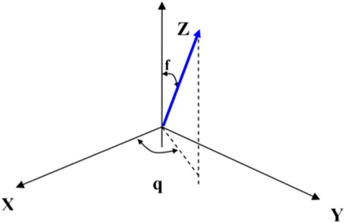
Figure 9. Angles for beam deflection.
3 Result and discussion
This section provides a comprehensive analysis of the effects of cutting parameters on residual stress and the role of tool coatings in controlling heat rate and temperature distribution in the cutting zone. Understanding these factors is crucial for optimizing machining performance, improving tool life, and ensuring superior surface integrity of the machined components.
3.1 Effect of cutting parameters on residual stress in dry turning environment
Numerical investigation was carried out using FEM to examine the effect of cutting parameters on surface and subsurface residual stresses (σhoop) induced after dry-hard turning. The workpiece modeling, tool modeling, friction modeling, and mesh refinement were carried out as described in previous sections. The residual stress volume averaging feature within AdvantEdge software was used to predict the residual stress which mimics X-ray diffraction test data. The cutting tool and its geometry used in the simulation and experimental work are discussed in detail in a subsequent section. The tests were conducted at various cutting conditions to understand their individual and interaction effect on residual stresses. Table 6 shows residual stress values at various cutting conditions in dry hard turning.
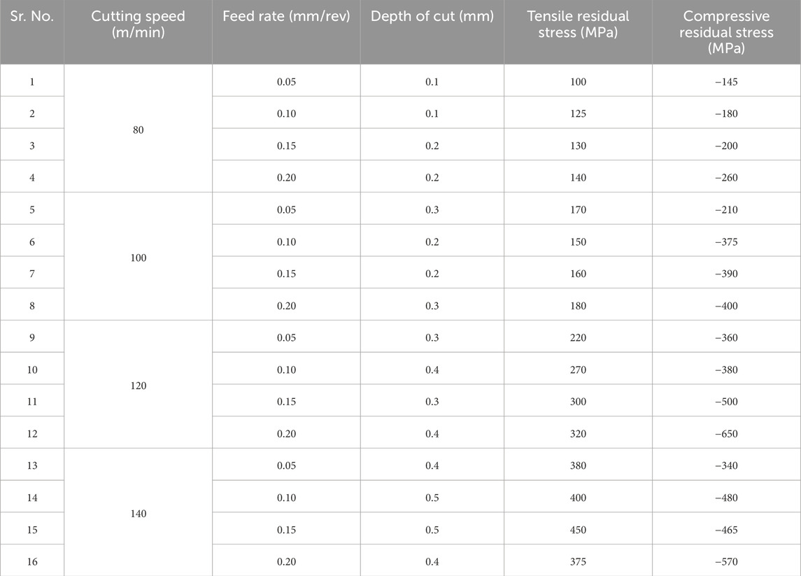
Table 6. Residual stress values at various cutting conditions in dry hard turning.
In the applied range of cutting conditions, the residual stresses were tensile in nature at surface and compressive in nature at subsurface, however, their magnitude varied, depending on the cutting conditions and cutting environment. Figures 10a–p) presents the graphs of residual stresses vs. distance beneath the surface under different cutting conditions in dry cutting environment. The influence of cutting parameters on residual stresses in dry turning of AISI 52100 hardened alloy steel of hardness 58 HRC were studied. Figures 10a–d shows the tensile residual stresses of (100, 125, 130, and 140 MPa) at the surface and compressive residual stresses of (−145, −180, −200, and −260 MPa) at sub-surface at v = 80 m/min, f= (0.05, 0.10, 0.15, and 0.20 mm/rev) and d= (0,1, 0.1, 0.2, and 0.2 mm) respectively. The tensile residual stresses of 125 MPa and 130 MPa were observed at a cutting speed 80 m/min and depth of cut 0.1 and 0.2 mm, respectively. The increase of feed rate in the range of 0.05–0.20 mm/rev at applied cutting speed generated higher compressive residual stresses at subsurface in the range of −145 MPa to −260 MPa, however, the less significant change was observed in tensile residual stress at the surface. Figures 10e–h shows the tensile residual stresses of (170, 150, 160, and 180 MPa) at the surface and compressive residual stresses of (−210, −375, −390, and −445 MPa) at subsurface at v = 100 m/min, f= (0.05, 0.10, 0.15, and 0.20 mm/rev) and d= (0.3, 0.2, 0.2, and 0.3 mm) respectively. It was shown that an increase in the depth of cut from 0.2 mm to 0.3 mm caused an insignificant increase in tensile residual stresses at surface, however, a minor increase of these stresses was observed. The significant increase in value of compressive residual stress of - 210 MPa to - 445 MPa at sub-surface was noticed at a feed rate of 0.05 mm–0.20 mm/rev. An increase of cutting speed from 80 to 100 m/min caused increased tensile residual stresses in the range of 125 MPa–170 MPa.
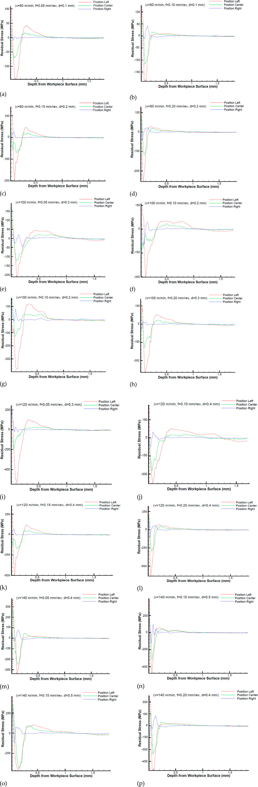
Figure 10. (a–p) Residual stress profile in turning of AISI 52100 hardened alloy steel at various cutting conditions under dry environment.
Figures 10i–l shows the tensile residual stresses of (220, 270, 300, and 320 MPa) at the surface and compressive residual stresses of (−360, −380, −500, and −650 MPa) at sub surface at v = 120 m/min, f= (0.05, 0.10, 0.15, and 0.20 mm/rev), and d= (0,3, 0.4, 0.4, and 0.4 mm) respectively. At cutting speed 120 m/min and depth of cut 0.3 and 0.4 mm, the tensile residual stresses of 220 MPa and 270 MPa were observed respectively. At the applied cutting speed of 120 m/min, the increase in feed rate range from 0.05 to 0.020 mm/rev caused higher compressive residual stresses in the range of −360 MPa to −650 MPa at subsurface. No significant influence was observed in tensile residual stress at the surface at applied feed range. Figures 10m–p shows the tensile residual stresses residual stresses of (380, 400, 450, and 375, MPa) at the surface and compressive residual stresses of (+340, −480, −465, and −570 MPa) at sub surface at v = 140 m/min, f= (0.05, 0.10, 0.15 & 0.20 mm/rev) and d= (0,4, 0.5, 0.5, and 0.4 mm) respectively. The tensile residual stresses at surface increased drastically from 170 MPa to 450 MPa over the cutting speed range of 100 m/min to 140 m/min it was also noticed that the compressive residual stress at sub-surface significantly increases at cutting speed 140 m/min and feed rate range 0.05–0.20 mm/rev combination, on the other hand depth of cut of 0.3 mm and 0.4 mm at applied cutting speed did not show significant effect on tensile residual stress. The results closely align with the experimental findings reported in the literature, validating the accuracy and reliability of the proposed model. (Leppert and Peng, 2012) (Chavan and Sargade, 2020).
3.2 Effect of coating material on heat and temperature distribution
This study explored how various coating materials affect heat and temperature distribution during machining using FEM. The coatings were chosen for their thermal conductivity and heat resistance. Temperature data collected from different points in cutting zone and on the tool surface, provided insights into the thermal behavior influenced by the coatings. Table 7 illustrates the machining conditions employed for modeling and simulating the process.
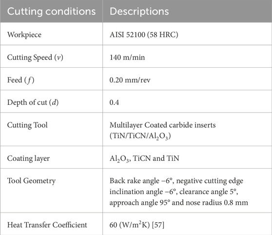
Table 7. Machining conditions applied for modelling the process.
The simulations were performed at cutting speed v = 140 m/min, fed rate f = 0.20 mm/rev and depth of cut d = 0.4 mm. From Figures 11a–d, the cutting temperature of 605°C with three layers of coating (Al2O3/TiCN/TiN-WC), 654°C with (TiCN/TiN-WC) coating, 682°C with (TiN-WC) coating and 718°C with uncoated WC cutting tool insert were observed. The significant reduction in cutting edge temperature was observed with Al2O3/TiCN/TiN-WC coating material as compared to other coating material; this is due to the decrease in thermal conductivity of Al2O3 material with increase in temperature. Al2O3 acts as a thermal barrier and does not allow heat to penetrate and distribute along the rake face of tool, as a result of which the carbide substrate remains partly thermally insulated by the coating. TiN coatings demonstrated a higher cutting edge temperature of 682°C, as it gets oxidize into TiO2 above 500°C. The significant reduction in cutting temperature of 16% was observed with Al2O3/TiCN/TiN-WC coating, 9% with TiCN/TiN-WC coating and 5% with TiN-WC coating as compared to uncoated carbide tool. It is thus revealed from the result that cutting tool coatings influences the heat transfer and temperature distribution in the cutting zone when turning of AISI 52100 hardened steel. Table 8 depicts the cutting temperature obtained at different coating material.
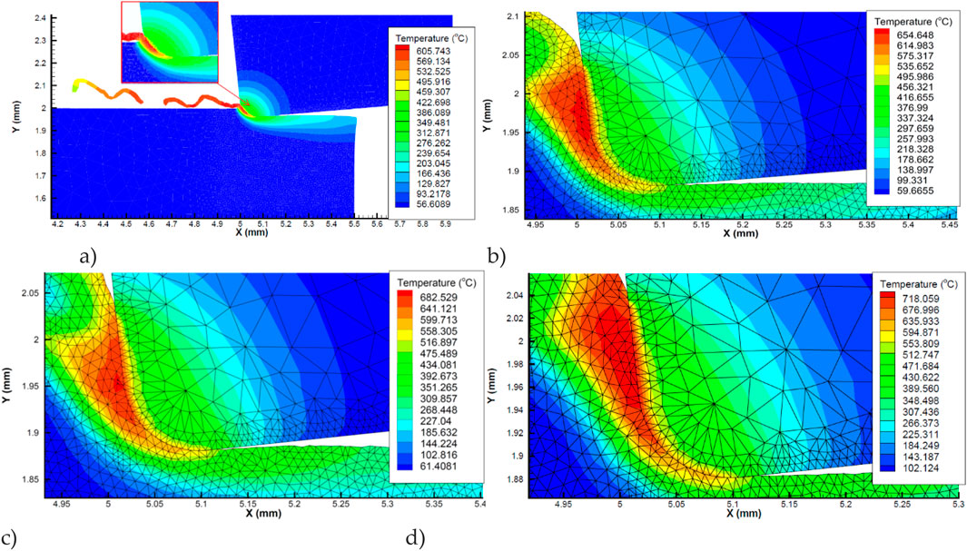
Figure 11. Contour plots of the temperature rise in the vicinity of the cutting edge at Vc = 140 m/min, f = 0.20 mm/rev and d = 0.4 mm for (a) Al2O3/TiCN/TiN coated carbide (b) TiCN/TiN coated carbide (c) TiN coated carbide (d) WC uncoated carbide tool.
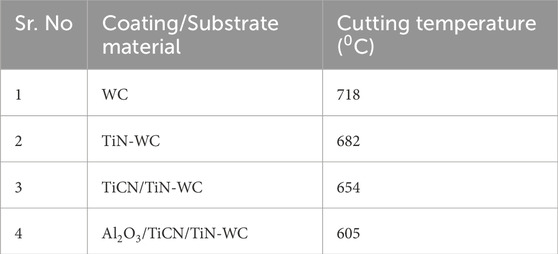
Table 8. Values of maximum temperature in tool (in 0C).
Figures 12a–d shows distribution of heat source at Vc = 140 m/min, f = 0.20 mm/rev and d = 0.4 mm for coated carbide and uncoated tools, it can be concluded based on cutting simulations that the heat rate increases in the cutting zone and changes for the cutting tool coating materials used. The minimum value of ec (volumetric specific cutting energy) equal to 11,111 W/mm3 was computed for an Al2O3/TiCN/TiN-WC coated carbide, whereas the maximum value of 19,444 W/mm3 was obtained for a WC uncoated carbide tool. The predicted results are in good agreement with those in the literature regarding the effect of cutting tool coating materials on the cutting edge temperature and volumetric heat generation (volume specific cutting energy) ec in hard turning under various cutting conditions (Grzesik et al., 2005).
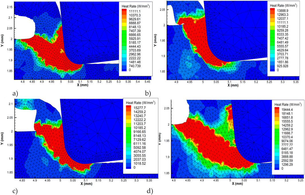
Figure 12. Distribution of heat source at Vc = 140 m/min, f = 0.20 mm/rev and d = 0.4 mm for (a) Al2O3/TiCN/TiN coated (b) TiCN coated (c) TiN coated (d) WC uncoated carbide tools.
3.3 Model validation
Finite element predictions of residual stresses closely align with experimental data reported in the literature, underscoring the reliability and accuracy of predictive model. The residual stress prediction through AdvantEdge’s residual stress volume averaging feature closely matched with the X-ray diffraction test data. Hence the approach, that was used to develop the finite element model and modeling procedure, is considered reliable for pre-process residual stress prediction using FEM. Hard turning tests were conducted using HK 150 grade MTCVD multilayer coated carbide inserts mounted on a PCLNR2020 K12 type right-hand tool holder. Table 9 presents a comparison between simulated and experimental values of cutting temperatures at different cutting conditions and tool coatings. It highlights the effectiveness of coatings in reducing heat generation and evaluates the accuracy of FEM simulations in predicting cutting temperatures. The error between simulated and experimental results ranges from 3.58% to 8.90%, indicating a reasonable agreement. Despite incorporating appropriate boundary conditions, isotropic material modeling, and thermo-physical properties, the observed discrepancy can be attributed to factors such as microstructural inhomogeneity, dynamic contact variations at the tool-chip-workpiece interface, and localized emissivity fluctuations phenomena that are inherently difficult to replicate within the constraints of current simulation techniques. Moreover, Al2O3/TiCN/TiN-WC coating was found to be more effective compared to other coatings, offering better thermal control.
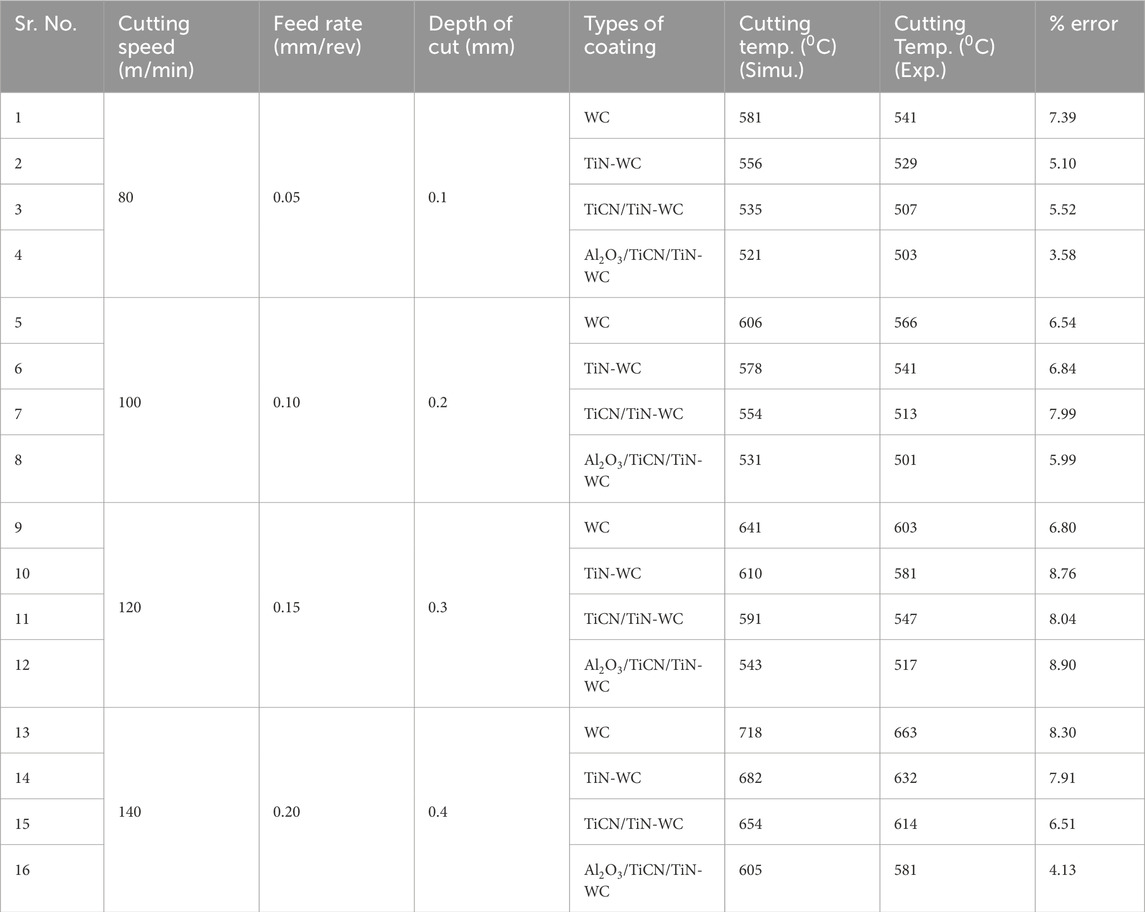
Table 9. Comparison of Simulated and experimental values of cutting temperature in tool (in 0C).
4 Conclusion
The study confirmed that machining parameters notably affect residual stress in dry hard turning. Elevated temperatures in the cutting zone raise surface tensile stress due to high thermal gradient. Cutting speed had the most significant impact, while depth of cut showed minimal effect. Feed rate mainly influenced stress beneath the surface with higher rates increasing compressive stress and shifting the peak deeper. The simulated results closely matched with existing X-ray diffraction data, offering practical guidance for optimizing cutting conditions to improve surface integrity of machined parts. The study also highlighted the impact of different coatings on cutting temperature and heat rate, with Al2O3 offering the best thermal insulation and resulting in the lowest cutting temperatures compared to the other coatings. The significant reduction in cutting temperature was observed in the range of 5%–16% with coated carbide tool, when compared to uncoated carbide tool. The relative percentage error between the experimental and simulated cutting temperature values was observed to range from 4% to 8%. A minimum heat rate of 11,111 W/mm3 was computed for an Al2O3/TiCN/TiN-WC coated carbide tool, while uncoated WC carbide tool exhibited a peak value of 19,444 W/mm3. The FEM predictions exhibited strong agreement with experimental results confirming the model’s accuracy in capturing thermal response, making it a useful tool for refining machining processes and improving product quality in industrial applications.
Future research should focus on integrating the machine learning with FEM models to predict cutting temperature and residual stresses under different cutting environments, enhancing the process optimization and machining performance.
Data availability statement
The original contributions presented in the study are included in the article/supplementary material, further inquiries can be directed to the corresponding author.
Author contributions
SM: Writing – original draft, Writing – review and editing, Conceptualization, Investigation. RP: Writing – original draft, Writing – review and editing, Data curation, Methodology, Supervision. MS: Data curation, Writing – original draft, Writing – review and editing, Formal Analysis, Project administration. CC: Project administration, Writing – original draft, Writing – review and editing, Funding acquisition, Resources, Methodology. YX: Resources, Writing – original draft, Writing – review and editing, Conceptualization, Methodology, Supervision, Visualization.
Funding
The author(s) declare that financial support was received for the research and/or publication of this article.
Acknowledgments
The Authors are thankful to Guangxi Science and Technology Program (No. AA24010001), Guangxi Natural Science Foundation (No. 2025GXNSFAA069536) and Ongoing Research Funding program, (ORF-2025-999), King Saud University, Riyadh, Saudi Arabia.
Conflict of interest
The authors declare that the research was conducted in the absence of any commercial or financial relationships that could be construed as a potential conflict of interest.
Generative AI statement
The author(s) declare that no Generative AI was used in the creation of this manuscript.
Publisher’s note
All claims expressed in this article are solely those of the authors and do not necessarily represent those of their affiliated organizations, or those of the publisher, the editors and the reviewers. Any product that may be evaluated in this article, or claim that may be made by its manufacturer, is not guaranteed or endorsed by the publisher.
References
Aslantas, K., Ucun, T. I., and çicek, A. (2012). Tool life and wear mechanism of coated and uncoated Al 2O 3/TiCN mixed ceramic tools in turning hardened alloy steel. Wear 274–275, 442–451. doi:10.1016/j.wear.2011.11.010
Astakhov, V. P. (2011). Machining of hard materials - definitions and industrial applications. 1, 32. doi:10.1007/978-1-84996-450-0_1
Bana, V., Karpuschewski, B., Kundrák, J., and Hoogstrate, A. M. (2007). Thermal distortions in the machining of small bores. J. Mater. Process. Technol. 191, 335–338. doi:10.1016/j.jmatprotec.2007.03.027
Bertolini, R., Bedekar, V., Ghiotti, A., Savio, E., Shivpuri, R., and Bruschi, S. (2020). Surface integrity and corrosion performances of hardened bearing steel after hard turning. Int. J. Adv. Manuf. Technol. 108 (7–8), 1983–1995. doi:10.1007/s00170-020-05352-4
Bordinassi, E. C., Stipkovic, M. F., Batalha, G. F., Delijaicov, S., and de Lima, N. B. (2006). Superficial integrity analysis in a super duplex stainless steel after turning. J. Achiev. Mater. Manuf. Eng.
Caruso, S., Outeiro, J. C., Umbrello, D., and Batista, A. C. (2014). Residual stresses in machining of AISI 52100 steel under dry and cryogenic conditions: a brief summary. Key Eng. Mater. 611-612, 1236–1242. doi:10.4028/www.scientific.net/KEM.611-612.1236
Ceretti, E., Filice, L., Umbrello, D., and Micari, F. (2007). ALE simulation of orthogonal cutting: a new approach to model heat transfer phenomena at the tool-chip interface. CIRP Ann. - Manuf. Technol. 56 (1), 69–72. doi:10.1016/j.cirp.2007.05.019
Chavan, A., and Sargade, V. (2020). Surface integrity of AISI 52100 steel during hard turning in different near-dry environments. Adv. Mater. Sci. Eng. 2020. doi:10.1155/2020/4256308
Chen, Z., Ding, F., Zhang, Z., Gu, D., Liao, Q., Chen, M., et al. (2024). The study on the effect of various tool wear indicators on the machining of MMCs. J. Mater. Res. Technol. 30, 231–244. doi:10.1016/j.jmrt.2024.03.010
Chinchanikar, S., and Choudhury, S. K. (2013). Wear behaviors of single-layer and multi-layer coated carbide inserts in high speed machining of hardened AISI 4340 steel. J. Mech. Sci. Technol. 27, 1451–1459. doi:10.1007/s12206-013-0325-2
Corrêa Ferreira, D., Viana Avelar Dutra, F., Gustavo Dourado da Silva, R., Metrevelle Marcondes de Lima e Silva, S., and Roberto Ferreira, J. (2023). Studying the effects of coatings on the thermal protection of cutting tools during turning via a nonlinear inverse heat conduction problem. Int. J. Adv. Manuf. Technol. 129 (7–8), 3009–3026. doi:10.1007/s00170-023-12473-z
Corrêa Ribeiro, C. A., Ferreira, J. R., and Lima e Silva, S. M. M. (2022). Thermal influence analysis of coatings and contact resistance in turning cutting tool using COMSOL. Int. J. Adv. Manuf. Technol. 118 (1–2), 275–289. doi:10.1007/s00170-021-07835-4
Dahlman, P., Gunnberg, F., and Jacobson, M. (2004). The influence of rake angle, cutting feed and cutting depth on residual stresses in hard turning. J. Mater. Process. Technol. 147, 181–184. doi:10.1016/j.jmatprotec.2003.12.014
Du, F., Lovell, M. R., and Wu, T. W. (2001). Boundary element method analysis of temperature fields in coated cutting tools. Int. J. Solids Struct. 38, 4557–4570. doi:10.1016/S0020-7683(00)00291-2
Elsheikh, A. H., Shanmugan, S., Muthuramalingam, T., Thakur, A. K., Essa, F. A., Ibrahim, A. M. M., et al. (2022). A comprehensive review on residual stresses in turning. Adv. Manuf. 10 (2), 287–312. doi:10.1007/s40436-021-00371-0
Feng, X., Liu, J., Hu, J., and Liu, Z. (2024). The influence of spray cooling parameters on workpiece residual stress of turning GH4169. 2024•mdpi.Com. 17, 2876. doi:10.3390/ma17122876
Grzesik, W., Bartoszuk, M., and Nieslony, P. (2005). Finite element modelling of temperature distribution in the cutting zone in turning processes with differently coated tools. J. Mater. Process. Technol. 164–165, 1204–1211. doi:10.1016/j.jmatprotec.2005.02.136
Han, S., Valiorgue, F., Cici, M., Pascal, H., and Rech, J. (2024). 3D residual stress modelling in turning of AISI 4140 steel. Prod. Eng. 18, 219–231. doi:10.1007/s11740-023-01241-3
Hao, G., Liu, Z., Liang, X., and Zhao, J. (2019). Influences of TiAlN coating on cutting temperature during orthogonal machining H13 hardened steel. Coatings 9, 355. doi:10.3390/coatings9060355
Hao, G., Tang, A., Zhang, Z., Xing, H., Xu, N., and Duan, R. (2024). Finite element simulation of orthogonal cutting of H13-hardened steel to evaluate the influence of coatings on cutting temperature. Coatings 14 (3), 293. doi:10.3390/coatings14030293
Hosseini, S. B., Beno, T., Klement, U., Kaminski, J., and Ryttberg, K. (2014). Cutting temperatures during hard turning - measurements and effects on white layer formation in AISI 52100. J. Mater. Process. Technol. 214 (6), 1293–1300. doi:10.1016/j.jmatprotec.2014.01.016
Hoyne, A. C., Nath, C., and Kapoor, S. G. (2015). On cutting temperature measurement during titanium machining with an atomization-based cutting fluid spray system. J. Manuf. Sci. Eng. Trans. ASME 137 (2), 1–7. doi:10.1115/1.4028898
Jiang, X., Cai, Y., Liu, W., Guo, M., Zhou, H., Xu, Z., et al. (2023). Residual compressive stress prediction determined by cutting-edge radius and feed rate during milling of thin-walled parts. Int. J. Adv. Manuf. Technol. 124, 773–788. doi:10.1007/s00170-022-10394-x
Journal, U., and Mechanical, O. F. (2024). “Increase productivity of hard-to-machine materials by preventive heating of the workpiece,” vol. X, no. 2, pp. 66–80.
Kadirgama, K., and Bakar, R. A. (2005). “Modeling of residual stress,” in Finite Element Analysis – From Biomedical Applications to Industrial Developments. Rijeka, Croatia: InTech, 2, 3–161.
Kıvak, T., Sarıkaya, M., Yıldırım, Ç. V., and Şirin, Ş. (2020). Study on turning performance of PVD TiN coated Al2O3+TiCN ceramic tool under cutting fluid reinforced by nano-sized solid particles. J. Manuf. Process. 56, 522–539. doi:10.1016/j.jmapro.2020.05.017
Kurniawan, D., Yusof, N. M., and Sharif, S. (2010). Hard machining of stainless steel using wiper coated carbide: tool life and surface integrity. Mater. Manuf. process. 25, 370–377. doi:10.1080/10426910903179930
Kusiak, A., Battaglia, J. L., and Rech, J. (2005). Tool coatings influence on the heat transfer in the tool during machining. Surf. Coatings Technol. 195, 29–40. doi:10.1016/j.surfcoat.2005.01.007
Lalwani, D. I., Mehta, N. K., and Jain, P. K. (2008). Experimental investigations of cutting parameters influence on cutting forces and surface roughness in finish hard turning of MDN250 steel. J. Mater. Process. Technol. 206, 167–179. doi:10.1016/j.jmatprotec.2007.12.018
Laubscher, R. F., Styger, G., and Oosthuizen, G. A. (2014). A numerical analysis of machining induced residual stresses of grade 5 titanium alloy. Stellenbosch, Cape Town: R D J. South African Inst. Mech. Eng. 30, 39–46.
Leppert, T., and Peng, R. L. (2012). Residual stresses in surface layer after dry and MQL turning of AISI 316L steel. Prod. Eng. 6 (4–5), 367–374. doi:10.1007/s11740-012-0389-3
Leveille, T., Valiorgue, F., Dumas, M., Masciantonio, U., Brosse, A., Karaouni, H., et al. (2024). 3D numerical modelling of residual stresses induced by reaming. J. Manuf. Process. 113, 47–60. doi:10.1016/j.jmapro.2024.01.050
Li, G., Lu, W., Huang, S., Zhang, X., and Ding, S. (2022). Analysis and prediction of residual stresses based on cutting temperature and cutting force in rough turning of Ti–6Al–4V. Heliyon 8, e11661. doi:10.1016/j.heliyon.2022.e11661
Luo, H., Wang, Y., and Zhang, P. (2020). Effect of cutting parameters on machinability of 7075-T651 aluminum alloy in different processing methods. Int. J. Adv. Manuf. Technol. 110, 2035–2047. doi:10.1007/s00170-020-05939-x
Özel, T., and Altan, T. (2000). Determination of workpiece flow stress and friction at the chip-tool contact for high-speed cutting. Int. J. Mach. Tools Manuf. doi:10.1016/S0890-6955(99)00051-6
Panda, A., Sahoo, A. K., Rout, A. K., Kumar, R., and Das, R. K. (2018). Investigation of flank wear in hard turning of AISI 52100 Grade steel using multilayer coated carbide and mixed ceramic inserts. Procedia Manuf. 20, 365–371. doi:10.1016/j.promfg.2018.02.053
Sadeghifar, M., Javidikia, M., Loucif, A., Jahazi, M., and Songmene, V. (2023). Experimental and numerical analyses of residual stress redistributions in large steel dies: influence of tempering cycles and rough milling. J. Mater. Res. Technol. 24, 395–406. doi:10.1016/j.jmrt.2023.03.044
Sahoo, A. K., and Sahoo, B. (2012). Experimental investigations on machinability aspects in finish hard turning of AISI 4340 steel using uncoated and multilayer coated carbide inserts. Meas. J. Int. Meas. Confed. 45, 2153–2165. doi:10.1016/j.measurement.2012.05.015
Sharif, S., and Rahim, E. A. (2007). Performance of coated- and uncoated-carbide tools when drilling titanium alloy-Ti-6Al4V. J. Mater. Process. Technol. 185, 72–76. doi:10.1016/j.jmatprotec.2006.03.142
Sharma, M. K., Alkhazaleh, H. A., Askar, S., Haroon, N. H., Almufti, S. M., and Al Nasar, M. R. (2024). FEM-supported machine learning for residual stress and cutting force analysis in micro end milling of aluminum alloys. Int. J. Mech. Mater. Des. 20 (5), 1077–1098. doi:10.1007/s10999-024-09713-9
Sofuoğlu, M. A., Haydarlar, G., and Tekkalmaz, M. (2025). Influence of cutting parameters on tool temperatures and residual stresses in machining aerospace alloys: a DEFORM 3D simulation approach. Adv. Eng. Forum 54, 19–28. doi:10.4028/p-2KlBaN
Thakare, A., and Nordgren, A. (2015). Experimental study and modeling of steady state temperature distributions in coated cemented carbide tools in turning. Procedia CIRP 31, 234–239. doi:10.1016/j.procir.2015.03.024
Tounsi, N., and El-Wardany, T. (2022). Finite element analysis of the effects of process representations on the prediction of residual stresses and chip morphology in the down-milling of Ti6Al4V: Part II: effect of flank wear and conventional uncut chip thicknesses in milling with finite cutting edge radius. J. Manuf. Sci. Eng. Trans. ASME, 1–40. doi:10.1115/1.4051288
Ucun, I., and Aslantas, K. (2011). Numerical simulation of orthogonal machining process using multilayer and single-layer coated tools. Int. J. Adv. Manuf. Technol. 54 (9–12), 899–910. doi:10.1007/s00170-010-3012-9
Umbrello, D., Filice, L., Rizzuti, S., and Micari, F. (2007). On the evaluation of the global heat transfer coefficient in cutting. Int. J. Mach. Tools Manuf. 47 (11), 1738–1743. doi:10.1016/j.ijmachtools.2006.12.002
Wan, M., Ye, X. Y., Wen, D. Y., and Zhang, W. H. (2019). Modeling of machining-induced residual stresses. J. Mater. Sci. 54, 1–35. doi:10.1007/s10853-018-2808-0
Wang, J., Zhang, D., Wu, B., and Luo, M. (2017a). Residual stresses analysis in ball end milling of nickel-based superalloy inconel 718. Mater. Res. 20 (6), 1681–1689. doi:10.1590/1980-5373-MR-2017-0561
Wang, J., Zhang, D., Wu, B., and Luo, M. (2017b). Numerical and empirical modelling of machining-induced residual stresses in ball end milling of inconel 718. Procedia CIRP 58, 7–12. doi:10.1016/j.procir.2017.03.177
Warren, A. W., and Guo, Y. B. (2009). Characteristics of residual stress profiles in hard turned versus ground surfaces with and without a white layer. J. Manuf. Sci. Eng. 131 (4), 0410041–04100410. doi:10.1115/1.3159046
Weng, J., Zhou, S., Zhang, Y., Liu, Y., and Zhuang, K. (2023). Numerical and experimental investigations on residual stress evolution of multiple sequential cuts in turning. Int. J. Adv. Manuf. Technol. 129, 755–770. doi:10.1007/s00170-023-12311-2
Yao, G., Liu, Z., Song, Q., Wang, B., and Cai, Y. (2022). Numerical prediction and experimental investigation of residual stresses in sequential milling of GH4169 considering initial stress effect. Int. J. Adv. Manuf. Technol. 119, 7215–7228. doi:10.1007/s00170-022-08740-0
Zhang, J., and Liu, Z. (2017). Transient and steady-state temperature distribution in monolayer-coated carbide cutting tool. Int. J. Adv. Manuf. Technol. 91, 59–67. doi:10.1007/s00170-016-9707-9
Zhang, J., Zhang, G., and Fan, G. (2022). Effects of tool coating materials and coating thickness on cutting temperature distribution with coated tools. Int. J. Appl. Ceram. Technol. 19, 2276–2284. doi:10.1111/ijac.14038
Zhang, S., and Liu, Z. (2008). An analytical model for transient temperature distributions in coated carbide cutting tools. Int. Commun. Heat. Mass Transf. 35, 1311–1315. doi:10.1016/j.icheatmasstransfer.2008.08.001
Zhao, J., Liu, Z., Ren, X., Wang, B., Cai, Y., Song, Q., et al. (2022). Coating-thickness-dependent physical properties and cutting temperature for cutting Inconel 718 with TiAlN coated tools. J. Adv. Res. 38, 191–199. doi:10.1016/j.jare.2021.07.009
Zhou, R. (2024). Modeling and simulation of residual stress in metal cutting process: a review. Adv. Mech. Eng. 16 (12), 1–13. doi:10.1177/16878132241307714
Zhou, T., Zhang, C., Sun, C., Cui, H., Tian, P., et al. (2024). Hybrid modeling with finite element—analysis—neural network for predicting residual stress in orthogonal cutting of H13. J. Mater. Res. Technol. 29, 4954–4977. doi:10.1016/j.jmrt.2024.02.126
Glossary
Keywords: hard turning, residual stresses, finite element method (FEM), strain-rate sensitivity, surface integrity, process innovation
Citation: Mane S, Patil RB, Siddiqui MIH, Chan CK and Xu Y (2025) Effect of cutting parameters and tool coating on residual stress and cutting temperature in dry hard turning of AISI 52100 steel using finite element method. Front. Mater. 12:1613630. doi: 10.3389/fmats.2025.1613630
Received: 17 April 2025; Accepted: 21 May 2025;
Published: 09 June 2025.
Edited by:
Chao Yang, South China University of Technology, ChinaReviewed by:
Zhenzhong Zhang, Shandong Jianzhu University, ChinaHongyu Xing, Shandong Jianzhu University, China
Copyright © 2025 Mane, Patil, Siddiqui, Chan and Xu. This is an open-access article distributed under the terms of the Creative Commons Attribution License (CC BY). The use, distribution or reproduction in other forums is permitted, provided the original author(s) and the copyright owner(s) are credited and that the original publication in this journal is cited, in accordance with accepted academic practice. No use, distribution or reproduction is permitted which does not comply with these terms.
*Correspondence: Yong Xu, eHV5b25nQGhjbnUuZWR1LmNu