 Yihai Zhang
 Beibei Sun
 Yi Ren
- 1China Academy of Safety Science and Technology, Beijing, China
- 2Cathay Safety Technology Co., Ltd., Beijing, China
This work aims to reveal the macro-meso fracture evolution responses of fault zone samples subjected to repeated freeze-thaw (FT) weathering utilizing digital image correlation technology (DIC). Remolded specimens were prepared and then subjection to FT cycles of 0, 20, 40, and 60, respectively. Testing results show that the degradation effect of freeze-thaw on the uniaxial compressive strength of the fault fracture zone rock masses is significant, with peak strengths deteriorating by 20.2%, 32.7%, and 45.2% for specimens subjected to 20, 40, and 60 cycles, respectively, compared to specimens without FT treatment. Due to the elastic mismatch between the fine-grained matrix and the rock blocks within the fault fracture zone, the strain and displacement fields during loading exhibit pronounced heterogeneous characteristics. It is shown that freeze-thaw treatment leads to increasingly complex failure modes, with the fracture patterns transitioning from tensile failure to conjugate shear failure as the number of FT cycle increases. It is suggested that the impact of freeze-thaw on the internal components of the fault fracture zone rock masses varies considerably, with frost heave forces readily developing at rock-soil interfaces, pores, and microcracks, resulting in damage propagation, and ultimately diminishing the rock mass’s resistance to deformation.
1 Introduction
As a typical discontinuous geological structure in the field of geotechnical engineering, faults possess reactivation characteristics that have become a hot topic of research in rock mass engineering, such as slope stability, mining exploitation, and underground space development. The relative movement and compression of the two sides of a fault lead to the fracturing of adjacent rock, forming a fracture zone that is approximately parallel to the fault plane, referred to as the fault fracture zone (Choi et al., 2016). Fault zone rock masses, including fault gouge, fault breccia, and shattered rock, present significant challenges in engineering due to their internal discontinuity, anisotropy, high heterogeneity, and environmental sensitivity.
Generally, the disturbance activation of fault zones results in the formation of numerous fine, non-cohesive fault gouges and weathered rock masses, leading to the creation of block-in-matrix rocks (bimrocks). Medley (1994) was the first to introduce the concept of bimrocks, defined as rock materials containing geologically significant blocks within a matrix, classifying fault fracture zone rock masses as a type of bimrock. However, due to variations in the geological characteristics of the blocks and matrix materials, as well as differences in the contact strength or bonding degree between them, many scholars have proposed alternative definitions. New terminologies have emerged to describe mixtures of fine particles and larger blocks, including block-matrix soils (bimsoils) (Kalender et al., 2014; Wang et al., 2019), rock-soil aggregates (RSA) (Li et al., 2004), and soil-rock mixtures (SRM) (Xu et al., 2006; Xu et al., 2011), encompassing geological structures such as heterolithic rocks, coarse volcanic breccias, conglomerates, colluvium, alluvium, fault rocks, and gravels. The static mechanical behavior of bimrocks has been extensively studied through laboratory compression tests (Sonmez et al., 2006), shear tests (Chang and Cheng, 2014), field push-shear tests (Coli et al., 2011; Avşar, 2021), and numerical simulations (Napoli et al., 2018). Furthermore, while previous research has primarily focused on the geomechanical responses of fault fracture zone rock masses, the tested materials often consist of artificial mixtures or fine-grained fault gouges lacking blocks (Yund et al., 1990; Krantz, 1991; Ferri et al., 2010). However, natural faults are characterized by highly weathered rock, particularly when engineering activities—such as excavation, blast vibrations, fluid injection, or release—induce the fragmentation of fault rocks. At various scales, fault fracture zone rock masses composed of fault breccia and shattered rock exhibit a mixed structure of fault gouge and larger blocks. The size of these mixtures ranges from millimeter-sized particles within the fault gouge to large boulders measuring tens to hundreds of meters. Focusing solely on either the breccia or the gouge within the fault fracture zone fails to comprehensively capture the mechanical properties of the fault fracture zone rock mass. Therefore, investigating the coupled mechanical characteristics of fault breccia and fault gouge is crucial for understanding the stability of fault fracture zones.
Moreover, due to the environmental sensitivity of fault fracture zones, these areas in cold regions are often subjected to repeated freeze-thaw cycles. Under freeze-thaw conditions, the phase transition of water to ice results in a volumetric expansion of approximately 9%. This associated frost heave pressure promotes the propagation of microcracks within the fault, posing a significant threat to the fault’s resistance to deformation and potentially leading to its activation. Existing studies have explored the physical and mechanical properties of various granular structures under freeze-thaw cycles. For instance, Bu and Wang (2015) conducted indoor triaxial tests to examine the mechanical characteristics of coarse-grained soils with varying fine particle content under freeze-thaw conditions, finding that the shear strength and resistance to shear of coarse-grained soils decrease with increasing freeze-thaw cycles, ultimately stabilizing. Zhu et al. (2018) focused on coarse-grained soils from the Sichuan-Tibet line, investigating the relationship between mechanical properties and moisture content under freeze-thaw effects, the testing results show that samples with lower moisture content exhibit increased shear strength post-freeze-thaw cycles. Chen et al. (2019) analyzed the impact of freeze-thaw cycles on the strength characteristics of embankment materials, noting that the density and shear strength of samples decrease following exposure to these cycles. Qu et al. (2020) investigated the mechanical properties of unsaturated coarse-grained soils containing clay under freeze-thaw cycles using resistivity models. Wang et al. (2022) studied the mechanical properties of fault bimrocks subjected to freeze-thaw cycles, indicating a reduction in elastic modulus with increasing cycle counts. Wang et al. (2024) performed indoor cyclic triaxial tests on fault bimrocks, it was found that the influence of freeze-thaw treatment on the strength, fatigue lifetime and dynamic modulus of bimrocks is obvious and the cracking among the rock-soil interface is significantly influenced by the freeze-thaw weathering. Due to the elastic mismatch between the fine-grained matrix and the larger, rigid rock blocks within fault fracture zone rock masses, the effects of freeze-thaw disturbances on internal components differ significantly. The frost heave forces readily develop at the interfaces, pores, and microcracks, leading to damage propagation, pore growth, and increased crack lengths, ultimately compromising the internal structure of the fault fracture zone rock mass. However, there is a paucity of research in the literature specifically addressing the influence of freeze-thaw cycles on the deformation and fracture evolution processes within fault fracture zone rock masses, making such studies crucial for understanding the stability of these zones.
Therefore, this study aims to reveal the deformation and fracture characteristics of fault fracture zone rock masses under freeze-thaw cycles. Due to the challenges associated with field sampling and specimen preparation, remolded specimens of the fault zone rock mass were created. Uniaxial compression tests were conducted on these remolded specimens subjected to 0, 20, 40, and 60 freeze-thaw cycles. Additionally, digital image correlation (DIC) technology was employed to characterize the full-field strain and displacement evolution patterns of the specimens, with the objective of revealing the macroscopic and microscopic fracture mechanisms of remolded fault fracture zone rock masses under freeze-thaw disturbances.
2 Materials and methods
2.1 Rock specimen preparation
In order to reveal the macroscopic and microscopic fracture evolution patterns of fault fracture zone rock masses under freeze-thaw cycles, this study conducted digital image correlation (DIC) tests on the rock masses post-freeze-thaw treatment under uniaxial compression. The fault fracture zone rock mass used in the experiments was sourced from the F1 fault at the Beizhan Iron Mine in Hejing, Xinjiang,as shown in Figure 1. Field sampling revealed that the rock mass consisted of fragmented fault breccia and weathered fault gouge (Figure 1a), making direct processing and shaping challenging. Monitoring of fault reactivation using real-time radar monitoring, as shown in Figure 1b, it shows the deformation contour of the fault fracture zone, the red color indicates the large deformation characteristics and failure occurs within the fault fracture zone. As a result, investigation of the macro-meso mechanical of fault material behavior is important to reveal the instability mechanism of fault zone. In this work, synthetic specimens with matrix density the same of the fault fracture zone rock mass were prepared for the macro-meso mechanical tests.
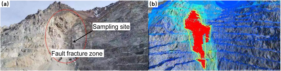
Figure 1. Description of the fault fracture zone in the open pit slope [(a) Sampling site of the fault gouge; (b) Monitoring of fault reactivation using real-time radar monitoring, the red color indicates large deformation and sliding region.].
A series of operations, including air-drying and sieving, were performed on the field samples to obtain the basic physical properties of the fault fracture zone rock mass. The dry density of the rock mass was determined to be 2.0 g/cm3, with a natural moisture content of 20%. The mass fractions of fault breccia and fault gouge were 60% and 40%, respectively. X-ray diffraction analysis was conducted to determine the mineral composition of the fault breccia, as shown in Figure 2a. The results indicated that the mineral components included 30% pyroxene, 28% quartz, 25% chlorite, 13% spinel, and 4% sphalerite. Figure 2b shows the particle size distribution of the fault gouge.
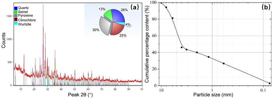
Figure 2. Composition of fault breccia [(a) Mineral composition from XRD analysis; (a) The particle size distribution].
The remolded specimens of the fault fracture zone rock mass were prepared in a rectangular shape measuring 120 mm × 60 mm × 30 mm, ensuring that the dry density, moisture content, and mass fraction of fault breccia were consistent with field samples. The threshold for the fault breccia and fault gouge was set at 2 mm, with the selected diameter range for the fault breccia between 4 and 10 mm. To achieve better integrity in the remolded specimens and to precisely control the dimensions and flatness, the preparation method shifted from a layered compaction approach to a consolidation method.
During the specimen preparation, a hydraulic jack and a custom mold, as illustrated in Figure 3a, were employed for compacting and demolding the soil-rock mixtures. The hydraulic jack system comprised an oil pump, oil delivery pipes, and the jack itself. The mold assembly included a base, a sample chamber, spacers, and a reaction frame. The oil pressure applied through the oil pump was used to compact the remolded sample within the mold, ensuring uniform density and structural integrity.
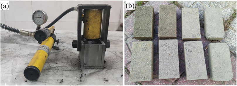
Figure 3. Specimen preparation procedures [(a) Specially designed mould; (b) Typical samples for the mechanical tests).
During the sample preparation, a total of 202.62 g of fault gouge and 303.93 g of fault breccia were first weighed using a balance and then thoroughly mixed with distilled water. To prevent the heavier fault breccia from settling at the bottom of the mold due to gravity, the mixed material was added to the mold in four increments. To facilitate demolding and avoid adhesion of the fault gouge to the mold, silicone oil was pre-applied to the interior of the mold and the spacers. The remolded sample was compacted using the hydraulic jack, with the penetration depth monitored throughout the compaction process. Compaction was ceased once the specified depth was reached, after which the jack continued to apply consolidation pressure equivalent to the initial compaction pressure for 1 h. This step was intended to simulate the original stress state of the specimen and minimize any potential rebound. To ensure the integrity of the specimen, the screws of the sample chamber and base were removed to obtain the complete remolded fault fracture zone rock mass specimen. The prepared remolded specimen is depicted in Figure 3b.
2.2 Experimental design
2.2.1 Freeze-thaw treatment
Due to its location in a high-cold region, the Hejing Beizhan Iron Mine experiences average monthly temperatures below zero from January to April and from September to December, with minimum temperatures dropping as low as −40°C. In contrast, from May to August, temperatures rise, peaking around 20°C, typically ranging from 5°C to 15°C. To simulate the intense and repeated freeze-thaw actions experienced by fault fracture zones in the high-altitude, cold environments of mining slopes, a digital low-temperature environmental chamber was employed for the freeze-thaw cycle testing of the prepared remolded specimens. The testing procedure commenced by placing the remolded specimens into the low-temperature environmental chamber, where they were frozen at −40°C for 12 h. Following this, the specimens were thawed at room temperature (20°C) for 12 h, thus completing one freeze-thaw cycle. The designed number of freeze-thaw cycles for the remolded specimens was set at 0, 20, 40, and 60 cycles. This approach was aimed at thoroughly assessing the mechanical properties and fracture behavior of the fault fracture zone rock masses under realistic environmental conditions.
2.2.2 Digital image correlation testing procedure
The uniaxial compression tests on the freeze-thaw treated remolded specimens of the fault fracture zone were conducted using a hydraulic servo rock testing machine, as illustrated in Figure 4. During the loading process, a digital image correlation (DIC) system was employed to accurately measure the deformation and displacement of the speckle-patterned remolded specimens. The DIC software is MatchID-2D (Wang, et al., 2021). To achieve quasi-static loading conditions, the loading rate of the testing machine was meticulously controlled at 0.06 mm/min. This careful control ensured that the mechanical response of the specimens could be effectively monitored, allowing for detailed analysis of their fracture behavior and deformation characteristics under the applied stress. The integration of the DIC system enabled comprehensive data collection regarding strain distribution and displacement fields throughout the testing, providing valuable insights into the material behavior of the fault fracture zone rock masses.
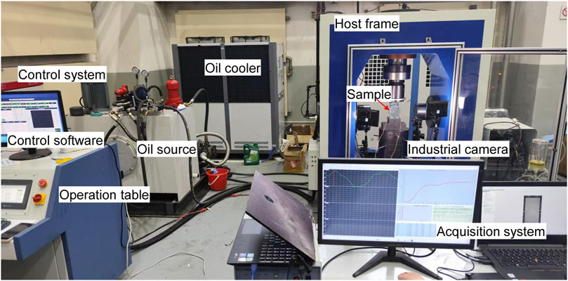
Figure 4. Testing system for the freeze-thawed samples. The testing devices contain the servo-controlled rock mechanics testing machine and the DIC system.
The digital image correlation (DIC) testing system utilizes a non-contact optical observation method to measure deformation information across the entire surface of the specimen. This system primarily consists of a camera module, LED light source, triggering data acquisition unit, and numerical image processing software. During the measurement process, the application of a speckle pattern on the specimen’s surface is crucial for measurement accuracy. Therefore, prior to the experiments, the prepared specimens were treated with a spray applicator to create a speckled surface. Before spraying, it was essential to ensure that the surface of the specimens was smooth, clean, and even, allowing the speckles to adhere firmly to the surface and ensuring high contrast in the speckle images. The spraying sequence began with a layer of matte white base coat applied to the specimen’s surface, followed by the application of a speckled black paint to create a high-contrast random pattern. Typically, each speckle should occupy approximately 4 to 6 image pixels for optimal measurement fidelity.
2.3 Basic principles of DIC technology
Digital Image Correlation (DIC) utilizes black-and-white speckle patterns sprayed on the specimen’s surface or the natural surface texture of the specimen itself. The technique is based on gray-level recognition and digital matching algorithms to solve for the displacement vectors of the same pixel coordinates in the continuously deformed images of the loaded specimen. This approach enables the extraction of full-field displacement and strain information across the surface of the specimen. The fundamental principles of DIC are illustrated in Figure 5. Through this method, high spatial resolution data can be obtained, allowing for a detailed understanding of the material’s deformation behavior and the distribution of strain during mechanical testing.
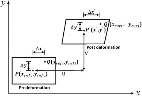
Figure 5. Schematic diagram of digital image correlation technology.
Figure 5 illustrates the deformation process of a single subset and the movement of its internal coordinate points before and after deformation. Let the center point of the subset before deformation be designated as P, which shifts to the point P′ after deformation. Consider an arbitrary coordinate point Q within the subset, which moves to the point Q′ post-deformation.
By simultaneously solving Equations 1–4, the coordinates of any point within the subset after deformation can be determined as follows:
From Equation 5, it is evident that once the deformation information of the subset’s center point is obtained, the deformation information for any point within the subset can be determined based on the corresponding deformation data of the center point.
3 Experimental results analysis
3.1 Stress-strain responses
The typical stress-strain curves for the specimens of the fault fracture zone under different freeze-thaw cycles are illustrated in Figure 6a. The shape of these stress-strain curves indicates that the freeze-thaw cycles have a significant impact on the strength and deformation characteristics of the specimens. As the number of freeze-thaw cycles increases, the peak compressive strength of the specimens deteriorates sharply, and there is a corresponding increase in the axial strain at failure. This suggests that repeated freeze-thaw disturbances exacerbate the damage to the fault fracture zone rock masses, making them more susceptible to large deformation and slip. Table 1 lists the mechanical parameters of the remolded specimens corresponding to various freeze-thaw cycles. From the table, it can be observed that the peak compressive strengths for the specimens subjected to 0, 20, 40, and 60 freeze-thaw cycles were 0.578 MPa, 0.461 MPa, 0.389 MPa, and 0.317 MPa, respectively. The corresponding peak axial strains were 0.925%, 1.065%, 1.311%, and 1.541%.
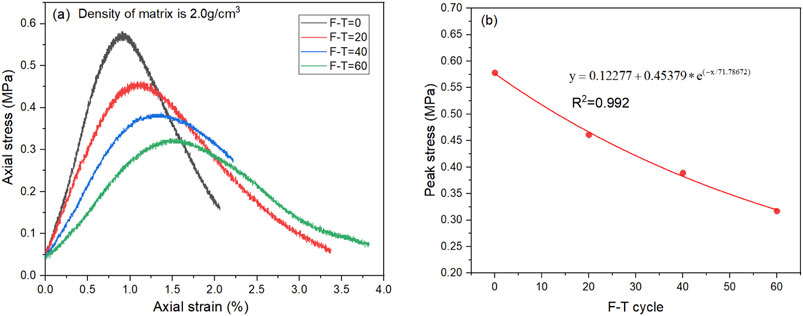
Figure 6. Stress-strain characteristics of remolded specimens of the fault fracture zone under different freeze-thaw cycles. (a) Stress-strain curves; (b) Relationship between peak strength and the freeze-thaw cycles.
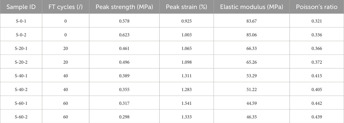
Table 1. Basic mechanical parameters of the tested specimens.
In comparison to the tested specimens that with no freeze-thaw treatment, those subjected to 20, 40, and 60 cycles experienced peak strength reductions of 20.2%, 32.7%, and 45.2%, respectively. Concurrently, the peak axial strains increased by 15.1%, 41.7%, and 66.6%. These results underscore the detrimental effects of freeze-thaw cycles on the mechanical integrity of fault fracture zone rock masses, highlighting the increased potential for failure and deformation under such conditions.
By establishing a mathematical relationship between the peak strength of the specimens and the number of freeze-thaw cycles, a better representation of the deterioration pattern can be achieved. The fitted strength degradation model, illustrated in Figure 6b, reveals that the peak strength exhibits an exponential decay relationship with the number of freeze-thaw cycles. The functional relationship can be expressed Equation 6:
In the equation, σf represents the peak compressive strength of the remolded specimens of the fault fracture zone rock mass, while n denotes the number of freeze-thaw cycles the specimens have undergone. The established relationship between y and x effectively characterizes the degradation of the material’s strength as a function of the repeated freeze-thaw cycles, highlighting the impact of environmental conditions on the structural integrity of the rock mass.
As the remolded specimens of the fault fracture zone rock mass undergo an increasing number of freeze-thaw disturbances, the trend in the changes of peak compressive strength exhibits an exponential decline. The initial freeze-thaw cycles lead to a significant reduction in strength, while the rate of strength degradation gradually levels off with further cycles. This indicates that the early freeze-thaw disturbances inflict greater internal damage on the fault fracture zone rock mass, and the degradation of the internal structure is the primary reason for the observed reduction in strength. The aforementioned peak strength degradation model can also serve to predict, to some extent, the changes in strength of the fault fracture zone rock mass when subjected to additional freeze-thaw cycles. This predictive capability is crucial for assessing the long-term performance and stability of rock masses in cold regions, where freeze-thaw cycling is prevalent.
3.2 Strain field evolution characteristics
In the macroscopic mechanical experiments, the generation, propagation, and stress concentration of microcracks are often not easily observable to the naked eye. However, by solving the full-field displacements and strains obtained from digital image correlation (DIC), we can visualize the evolution of the strain field at different loading stages for the remolded specimens of the fault fracture zone rock mass subjected to 0, 20, 40, and 60 freeze-thaw cycles, as shown in Figure 7. This allows for a clear depiction of the entire process of crack initiation, propagation, and coalescence during the failure of the specimens. From the figure, it can be observed that in the early stages of axial compression, the remolded specimens are in a state of compressive densification, with the Lagrangian strain field exhibiting a scattered distribution. The internal forces are relatively dispersed, and no strain concentration areas are present. As loading progresses into the linear elastic deformation phase, localized stress concentrations begin to develop at the edges of the specimens.

Figure 7. The full-field Lagrange strain evolution contour [(a–d) The FT cycle is 0, 20, 40 and 60, respectively.].
Approaching the high-stress phase near failure, particularly close to the peak stress, the full-field strain displays abrupt changes, marked by distinct areas of strain concentration. Subsequently, as cracks initiate and propagate within these concentrated strain zones, the final coalescence of cracks leads to the overall failure of the specimens. These observations emphasize the critical role of monitoring strain evolution through DIC in understanding the failure mechanisms of rock masses, particularly under cyclic loading conditions such as freeze-thaw cycles.
For specimens that have not undergone freeze-thaw cycles, the ultimate failure mode is characterized by tensile-shear failure. This is evident as the strain concentration band at the upper right of the specimen leads to the formation of tensile cracks, with the flanks of these cracks showing a tendency for propagation due to underlying shear microcracks. As the number of freeze-thaw cycles increases, localized strain concentrations appear at earlier loading stages, indicating that freeze-thaw cycles contribute to internal structural damage, thereby reducing the specimen’s capacity to resist deformation. Furthermore, the failure modes become increasingly complex with more freeze-thaw cycles. For the specimen subjected to 20 freeze-thaw cycles, the failure mode is marked by the penetration of primary shear cracks, accompanied by secondary tensile crack connections. In contrast, the specimen subjected to 40 freeze-thaw cycles primarily exhibits conjugate shear failure, revealing distinct “X”-shaped shear cracks. By the time the specimen has undergone 60 freeze-thaw cycles, multiple conjugate shear cracks are present, resulting in an even more intricate failure morphology. These observations underscore the significant impact of freeze-thaw cycles on the failure mechanisms of rock masses, highlighting the need for careful consideration of environmental factors in geotechnical engineering applications.
3.3 Evolution characteristics of displacement field
Figure 8 illustrates the evolution of the displacement field of the faulted rock mass specimens after undergoing 0, 20, 40, and 60 freeze-thaw cycles during different loading stages. The evolution of the displacement field primarily reflects the changes in both horizontal and vertical displacements throughout the loading process. Initially, the specimens experience primarily vertical compression; however, as the load increases, the horizontal displacement grows, indicating a trend toward shear failure.
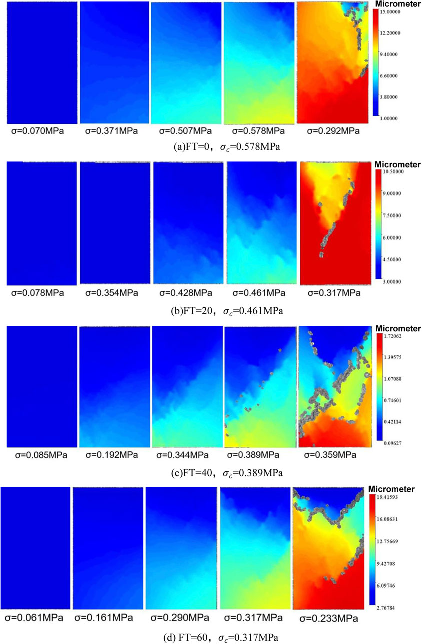
Figure 8. The full-field displacement evolution contour [(a–d) The FT cycle is 0, 20, 40 and 60, respectively.].
Throughout the loading process, the deformation of the specimens is non-uniform, with greater displacements occurring in regions closer to the direction of the applied load. This uneven deformation contributes significantly to the failure mechanisms, as crack surfaces typically develop in these areas of non-uniform deformation. With an increasing number of freeze-thaw cycles, the non-uniformity of deformation becomes increasingly pronounced, and the failure modes of the specimens become more complex. This highlights the critical influence of environmental factors on the mechanical behavior and stability of faulted rock masses.
Figure 9 shows the uniaxial compression failure morphology of the bimrock samples subjected to freeze-thaw cycles of 0, 20, 40, and, 60 respectively. It is shown that the samples with the most freeze-thaw cycles have the most fragmented fracture morphology, resulting in more and larger cracks. This indicates that as the number of freeze-thaw cycles increases, the fragmentation degree of the reformed samples also increases. The cracks produced are relatively coarse and numerous, and the fracture surface is more obvious. The reason is that the freeze-thaw cycle action generates frost heave force, causing damage to the internal structure of the sample, reducing the bonding degree between soil and rock particles, and transforming from brittle failure to plastic failure. The final fracture morphology of the sample is mostly shear failure, generating longitudinal shear cracks, presenting an X-shaped failure mode.
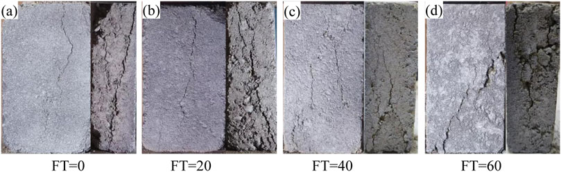
Figure 9. The final failure morphology of the typical bimrock samples subjected to various freeze-thaw cycles.
3.4 Analysis of spatial displacement along characteristic measurement lines
To clearly illustrate the displacement and movement of the specimens during uniaxial compression failure, and to reveal the displacement patterns under varying freeze-thaw disturbance cycles, monitoring lines were arranged as shown in Figure 10 to record the changes in displacement. These monitoring lines enable a detailed analysis of how displacement evolves throughout the loading process, providing insights into the mechanisms of failure and the impact of freeze-thaw cycles on the specimen’s structural integrity.
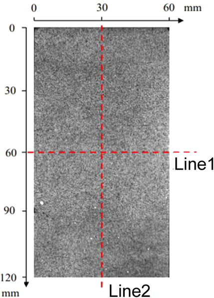
Figure 10. The displacement monitoring line, Line 1 is vertical to the loading direction, and Line 2 is parallel to the loading direction.
The vertical and horizontal displacement distributions along the monitoring lines for specimens subjected to different freeze-thaw cycle counts are not uniform. Figures 11, 12 presents the spatial displacement variations for the reconstituted specimens of the fault fracture zone. For the specimen with zero freeze-thaw cycles, the peak stress strength is 0.578 MPa, with a maximum vertical displacement of 0.9482 mm at monitoring line 1 and a maximum horizontal displacement of 0.1872 mm at monitoring line 2. For the specimen subjected to 20 freeze-thaw cycles, the peak stress strength is 0.461 MPa, resulting in a maximum vertical displacement of 1.002 mm at monitoring line 1 and a maximum horizontal displacement of 0.1335 mm at monitoring line 2. For the specimen subjected to 40 freeze-thaw cycles, the peak stress strength is 0.389 MPa, with a maximum vertical displacement of 1.1852 mm at monitoring line 1 and a maximum horizontal displacement of 0.2108 mm at monitoring line 2. Lastly, for the specimen with 60 freeze-thaw cycles, the peak stress strength is 0.317 MPa, showing a maximum vertical displacement of 1.3081 mm at monitoring line 1 and a maximum horizontal displacement of 0.193 mm at monitoring line 2. These results indicate that as the number of freeze-thaw cycles increases, both the vertical and horizontal displacements tend to increase, reflecting the adverse effects of freeze-thaw damage on the structural integrity of the fault fracture zone rock mass.
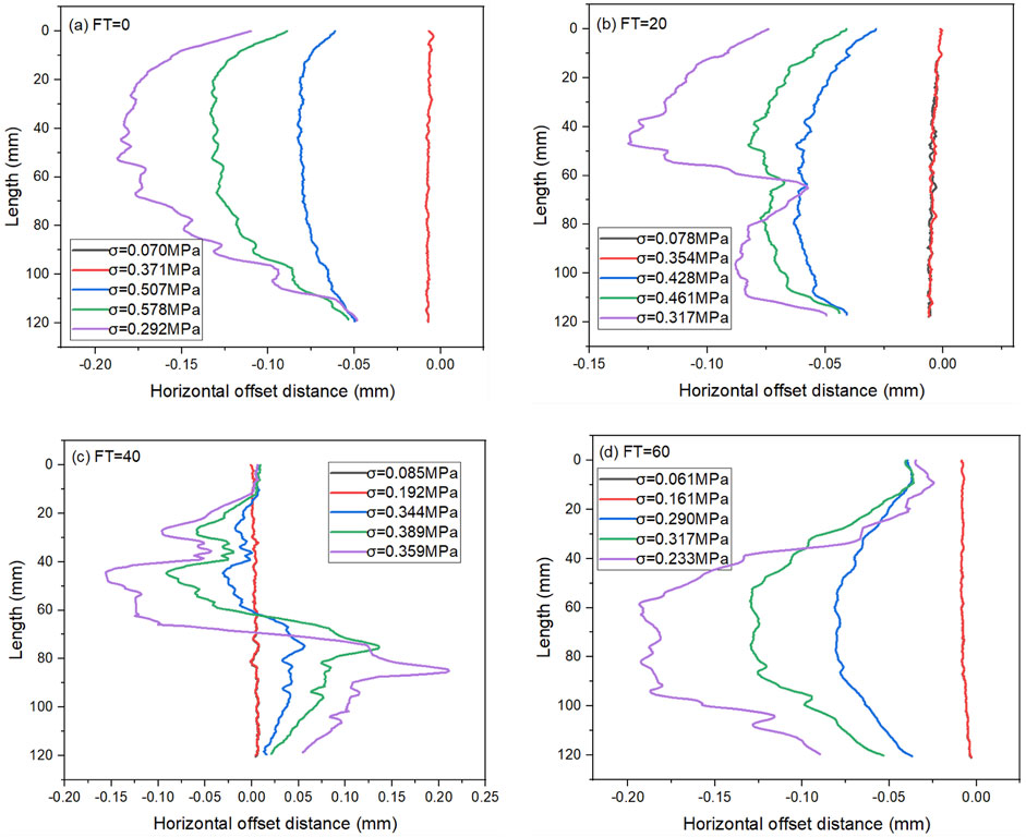
Figure 11. Horizontal deviation distance of the monitoring line under compression [(a–d): The FT cycle number is 0, 20, 40, and 60, respectively.].
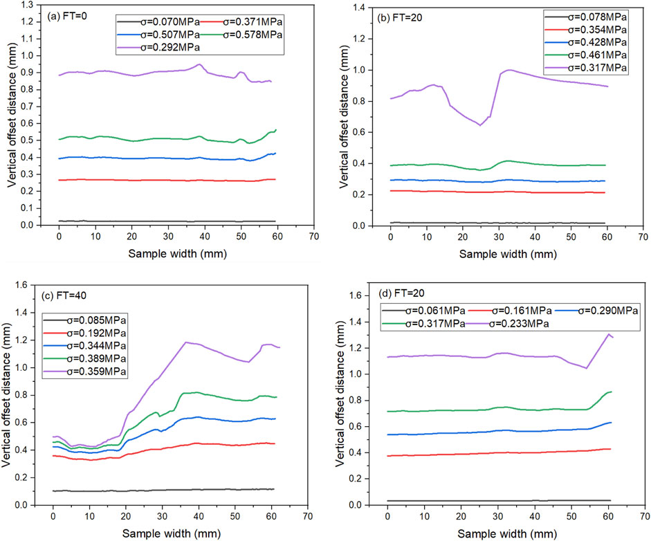
Figure 12. Vertical deviation distance of the monitoring line under compression [(a–d): The FT cycle number is 0, 20, 40, and 60, respectively.].
4 Summary and conclusion
This study primarily investigates the deformation and failure characteristics of reconstituted specimens of the fault fracture zone subjected to zero, 20, 40, and 60 freeze-thaw cycles during uniaxial compression loading. The effects of freeze-thaw cycles on the strength degradation of the fault fracture zone rock mass were revealed, and the evolution of strain and displacement during the failure process of freeze-thaw damaged specimens was characterized by using Digital Image Correlation (DIC) technology. The following main conclusions were drawn:
(1) The freeze-thaw cycles significantly deteriorated the reconstituted specimens of the fault fracture zone rock mass. As the number of freeze-thaw cycles increased, the peak compressive strength exhibited an exponential decline. Early freeze-thaw disturbances induced severe internal structural damage in the specimens, and this damage was the primary reason for the reduction in strength.
(2) DIC results demonstrated that freeze-thaw cycles led to more complex failure patterns in the reconstituted specimens. With an increasing number of freeze-thaw cycles, the failure mode transitioned from tensile-shear failure to conjugate shear failure. Freeze-thaw damage caused local strain concentrations to occur at earlier loading stages, thereby reducing the specimens' ability to resist deformation.
(3) Freeze-thaw cycles exacerbated the uneven deformation of the reconstituted specimens of the fault fracture zone during the loading process, which was a primary cause of crack initiation. Initially, the specimens predominantly experienced vertical compression; however, as the load increased, the increase in horizontal displacement led to a tendency for shear failure in the specimens.
Data availability statement
The original contributions presented in the study are included in the article, further inquiries can be directed to the corresponding author.
Author contributions
YZ: Funding acquisition, Software, Formal Analysis, Writing – original draft, Visualization, Resources, Supervision, Methodology, Project administration, Investigation, Conceptualization, Validation, Data curation. BS: Methodology, Investigation, Data curation, Funding acquisition, Writing – review and editing, Validation, Resources, Formal Analysis. YR: Resources, Conceptualization, Investigation, Validation, Visualization, Writing – review and editing, Methodology, Software.
Funding
The author(s) declare that financial support was received for the research and/or publication of this article. This article is funded by the Research, Development and Demonstration Application of Key Technologies for Precise Monitoring and Early Warning of Slip on High and Steep Slopes (2024EMST080802), and Fundamental Science Research Foundation of China Academy of Safety Science and Technology (2024JBKY20).
Conflict of interest
Authors YZ, BS, and YR were employed by Cathay Safety Technology Co., Ltd.
Generative AI statement
The author(s) declare that no Generative AI was used in the creation of this manuscript.
Publisher’s note
All claims expressed in this article are solely those of the authors and do not necessarily represent those of their affiliated organizations, or those of the publisher, the editors and the reviewers. Any product that may be evaluated in this article, or claim that may be made by its manufacturer, is not guaranteed or endorsed by the publisher.
References
Avşar, E. (2021). An experimental investigation of shear strength behavior of a welded bimrock by meso-scale direct shear tests. Eng. Geol. 294, 106321. doi:10.1016/j.enggeo.2021.106321
Bu, J. Q., and Wang, T. L. (2015). Influences of freeze-thaw and fines content on mechanical properties of coarse-grained soil. Chin. J. Geotechnical Eng. 37 (4), 608–614. doi:10.11779/CJGE201504005
Chang, K. T., and Cheng, M. C. (2014). Estimation of the shear strength of gravel deposits based on field investigated geological factors. Eng. Geol. 171, 70–80. doi:10.1016/j.enggeo.2013.12.014
Chen, T., Bao, Q. C., Wang, W., Yin, Y., Zhang, B. Y., and Sun, X. (2019). Experimental study on deformation characteristics and shear strength of rockfill under freeze-thaw cycle. J. Hydroelectr. Power 38 (3), 134–141. doi:10.11660/slfdxb.20190315
Choi, J. H., Edwards, P., Ko, K., and Kim, Y. S. (2016). Definition and classification of fault damage zones: a review and a new methodological approach. Earth-Science Rev. 152, 70–87. doi:10.1016/j.earscirev.2015.11.006
Coli, N., Berry, P., and Boldini, D. (2011). In situ non-conventional shear tests for the mechanical characterisation of a bimrock. Int. J. Rock Mech. Min. 48 (1), 95–102. doi:10.1016/j.ijrmms.2010.09.012
Ferri, F., DiToro, G., Hirose, T., and Shimamoto, T. (2010). Evidence of thermal pressurization in high-velocity friction experiments on smectite-rich gouges. Terra nova. 22 (5), 347–353. doi:10.1111/j.1365-3121.2010.00955.x
Kalender, A. Y. C., Sonmez, H., Medley, E., Tunusluoglu, C., and Kasapoglu, K. E. (2014). An approach to predicting the overall strengths of unwelded bimrocks and bimsoils. Eng. Geol. 183, 65–79. doi:10.1016/j.enggeo.2014.10.007
Krantz, R. W. (1991). Measurements of friction coefficients and cohesion for faulting and fault reactivation in laboratory models using sand and sand mixtures. Tectonophysics 188 (1–2), 203–207. doi:10.1016/0040-1951(91)90323-k
Li, X., Liao, Q. L., and He, J. M. (2004). In-situ tests and a stochastic structural model of rock and soil aggregate in the three gorges reservoir area, China. China Int. J. Rock Mech. Min. 41, 702–707. doi:10.1016/j.ijrmms.2004.03.122
Medley, E. W. (1994). The engineering characterization of melanges and similar block-in-matrix rocks (bimrocks). Berkeley: Doctoral dissertation, University of California.
Napoli, M. L., Barbero, M., Ravera, E., and Scavia, C. (2018). A stochastic approach to slope stability analysis in bimrocks. Int. J. Rock Mech. Min. 101, 41–49. doi:10.1016/j.ijrmms.2017.11.009
Qu, Y. L., Ni, W. K., Niu, F. J., Mu, Y. h., Chen, G. l., and Luo, J. (2020). Mechanical and electrical properties of coarse-grained soil affected by cyclic freeze-thaw in high cold regions. J. central south Univ. 27, 853–866. doi:10.1007/s11771-020-4336-8
Sonmez, H., Gokceoglu, C., Medley, E. W., Tuncay, E., and Nefeslioglu, H. A. (2006). Estimating the uniaxial compressive strength of a volcanic bimrock. Int. J. Rock Mech. Min. 43 (4), 554–561. doi:10.1016/j.ijrmms.2005.09.014
Wang, Y., Chen, Z., Xia, Y., Li, P., and Cai, M. (2024). The effect of cyclic disturbed frequency on mechanical, acoustic emission and crack pattern for rock–backfill composites exposed to fatigue loading condition. Rock Mech. Rock Eng., 1–26. doi:10.1007/s00603-025-04490-z
Wang, Y., Li, C. H., and Hu, Y. Z. (2019). 3D image visualization of mesostructural changes in a bimsoil under uniaxial compression using X-ray computed tomography (CT). Eng. Geol. 248, 61–69. doi:10.1016/j.enggeo.2018.11.004
Wang, Y., Mao, T. Q., Zhang, B., Xia, Y. J., and Yi, X. F. (2022). Macro-meso fatigue damage and instability of a fault bimrock exposed to multistage cyclic triaxial loads with different confining pressure. Fatigue and Fract. Eng. Mater. and Struct. 45, 2576–2594. doi:10.1111/ffe.13770
Wang, Y., Zhu, C., Zhang, B., and Hou, Z. (2021). Full-field deformation characteristics of anisotropic marble under compression revealed by 3D digital image correlation. Lithosphere 4, 1098235. doi:10.2113/2021/1098235
Xu, W. J., Wang, S., Zhang, H. Y., and Zhang, Z. L. (2006). Discrete element modelling of a soil-rock mixture used in an embankment dam. Int. J. Rock Mech. Min. 86, 141–156. doi:10.1016/j.ijrmms.2016.04.004
Xu, W. J., Xu, Q., and Hu, R. L. (2011). Study on the shear strength of soil–rock mixture by large scale direct shear test. Int. J. Rock Mech. Min. 48 (8), 1235–1247. doi:10.1016/j.ijrmms.2011.09.018
Yund, R. M., Blanpied, T., and Weeks, J. (1990). Amorphous material in high strain experimental fault gouges. J. Geophys Res. 95 (B10), 589–602. doi:10.1029/JB095iB10p15589
Keywords: freeze-thaw cycle, fault zone rock mass, DIC technology, fracture evolution, deformation
Citation: Zhang Y, Sun B and Ren Y (2025) Full-field deformation evolution characteristics of freeze-thawed fault zone rock mass revealed by digital image correlation: a lab-scale investigation. Front. Mater. 12:1615128. doi: 10.3389/fmats.2025.1615128
Received: 20 April 2025; Accepted: 06 June 2025;
Published: 24 June 2025.
Edited by:
Bing Bai, Beijing Jiaotong University, ChinaReviewed by:
Mohammad M. Karimi, Tarbiat Modares University, IranXueyi Shang, Chongqing University, China
Yi Wang, Chinese Academy of Sciences (CAS), China
Copyright © 2025 Zhang, Sun and Ren. This is an open-access article distributed under the terms of the Creative Commons Attribution License (CC BY). The use, distribution or reproduction in other forums is permitted, provided the original author(s) and the copyright owner(s) are credited and that the original publication in this journal is cited, in accordance with accepted academic practice. No use, distribution or reproduction is permitted which does not comply with these terms.
*Correspondence: Yi Ren, cnltcjA2MTFAMTYzLmNvbQ==