 Tao Liu
 Liang Chen3*
 Peng Wu
 Kai Zhang
- 1State Key Laboratory of Intelligent Construction and Healthy Operation and Maintenance of Deep Underground Engineering, China University of Mining and Technology, Xuzhou, China
- 2School of Civil Engineering, Xuzhou University of Technology, Xuzhou, China
- 3State Key Laboratory for Fine Exploration and Intelligent Development of Coal Resources, China University of Mining and Technology, Xuzhou, China
- 4School of Physics and New Energy, Xuzhou University of Technology, Xuzhou, China
Backfilling in underground mining is a widely adopted technique, often employing cement-based or geopolymer materials. However, the high cost and logistical challenges associated with these materials in remote mining locations necessitate alternative solutions. Loess materials offer a viable option for reducing production expenses and mitigating environmental impact. Despite this, the mechanical properties of loess-based cemented materials have been insufficiently investigated. This study introduces a novel slag-loess-based cemented backfill material. A three-dimensional model of the backfill material was constructed using Avizo software, and a numerical calculation model, incorporating the actual three-dimensional geometry of aggregate particles, was developed using PFC3D software. The influence of confining pressure σ3, curing temperature TC, and age TA on the crack evolution, force chain evolution, and particle failure characteristics during the loading process of the cemented backfill material was systematically examined. Results demonstrate that increasing confining pressure σ3 accelerates crack initiation and propagation, concurrently increasing the maximum value of the dominant force chain within the specimen at each stage. An increase in age TA has a limited effect on the proportion and quantity of final tensile-shear cracks, though it does intensify the specimen’s ultimate shear failure tendency. At lower curing temperatures (5°C), a significant impact on crack formation is observed, with this effect diminishing as curing temperature TC increases. The macroscopic failure modes of the specimens, across varying temperatures, predominantly exhibit shear failure.
1 Introduction
Within the scope of coal mine production in China, backfilling mining is a critical element of green mining technologies. Current research on cemented backfill materials primarily concentrates on conventional Portland cement (Wu et al., 2025a; Wu et al., 2022). However, cement production is associated with significant CO2 emissions, which poses a substantial environmental threat (Lv et al., 2022). Recent advancements in environmentally friendly mining concepts have shifted research on backfill materials from traditional Portland cement to industrial waste materials, including slag, red mud, and fly ash. The resulting binding products of these materials, classified as geopolymers, differ from cement hydration products (Amran et al., 2021; Qaidi et al., 2022; Zhuang et al., 2016). Compared to cement-based materials, geopolymers demonstrate superior mechanical properties, enhanced corrosion resistance, improved durability, and reduced carbon emissions (Al-Majidi et al., 2018; Huang et al., 2019; Nadoushan and Ramezanianpour, 2016). While research on geopolymer backfill materials derived from industrial waste is extensive, loess, a material with inherent binding properties, has been largely overlooked. The use of loess-based materials could potentially reduce production costs and environmental impact. The relatively consistent mineralogical composition of loess across different geographical locations supports its large-scale application in cemented backfill (Lv et al., 2022). Historical evidence indicates the use of loess as a binding agent in ancient construction practices globally, including adobe brick production and fortification construction (Delgado and Guerrero, 2007). Recent studies have investigated the binding characteristics of loess, primarily focusing on enhancing its mechanical properties through water glass for soil stabilization (Gu et al., 2021; Hanegbi and Katra, 2020) or in developing novel waterproof coatings (Dassekpo et al., 2021). These studies suggest the potential of loess as a cemented backfill component; however, its high consistency, limited reactivity, and relatively low strength necessitate its use in composite formulations to improve its applicability.
The mechanical properties of cemented backfill directly influence its strength, support capacity, and the stability of the surrounding rock, thereby affecting the success of mine backfilling operations (Wu et al., 2025b; Wu et al., 2024). These properties are primarily governed by the binder type, raw materials, curing age, curing temperature, and confining pressure (Li et al., 2023; Yao et al., 2022). Cement-based binders are currently the most common in backfill applications. Research has investigated the influence of cement type and dosage on backfill mechanical properties, leading to the determination of optimal mass ratios (Ercikdi et al., 2009b). Driven by increasingly stringent environmental regulations, the partial or complete replacement of cement with novel binding materials, particularly industrial by-products like fly ash, is gaining traction (Ercikdi et al., 2009a; Oner et al., 2005; Peyronnard and Benzaazoua, 2011). The curing age of cemented backfill significantly impacts its early strength, compressive strength, and overall mechanical performance, directly affecting the support provided to the surrounding rock and the backfill’s stability under complex stress conditions (He et al., 2021; Huang et al., 2011; Jafari et al., 2020; Jiang et al., 2022a). The existing research has largely overlooked loess-based cemented backfill. The hydrochemical reactions within cemented backfill materials are inherently dependent on curing temperature, which significantly impacts the backfill’s mechanical properties (Bull and Fall 2020; Chen et al., 2021a; Xu et al., 2020b). During practical engineering applications, the hydration process of cemented backfill generates heat, thereby increasing the backfill temperature. This temperature fluctuation subsequently affects the reaction rate of the slurry, influencing the development of backfill strength (Abd-El Aziz et al., 2012; Narmluk and Nawa, 2011). Jiang et al. (2017); Jiang et al. (2016) found that low-temperature conditions impede the hydration process of cementing materials. While elevated temperatures promote the early strength development of cement-based cemented backfill materials, excessive heat can suppress hydration reactions, leading to a reduction in the later-stage strength of the backfill (Escalante-Garcia and Sharp, 2001; Paul and Glasser, 2000). Additional studies have shown a positive correlation between backfill compressive strength and temperature below 200°C; conversely, a negative correlation is observed (Cui and Fall 2016; Escalante-Garcia and Sharp, 2001; Fall and Samb, 2009; Pokharel and Fall 2013; Wang et al., 2016). Confining pressure also significantly influences the stability and mechanical characteristics of the backfill (Wu et al., 2021; Xu et al., 2020a; Yang et al., 2020). Research indicates that confining pressure significantly affects the strength and deformation characteristics of cemented backfill materials (Si et al., 2025), with material proportions and curing age under varying confining pressures notably affecting backfill strength (Arslan et al., 2021; Fall et al., 2007). Given the complex stress environments encountered by backfill in practical engineering (Luo et al., 2025; Shi et al., 2024; Shi et al., 2023), it is essential to investigate the mechanical properties of cemented backfill materials under diverse stress conditions.
Currently, research on the mesoscopic mechanical properties of slag-loess based backfill materials is limited. To comprehensively investigate the mesomechanical behavior of this material, this study employed CT scanning to obtain a series of cross-sectional images of aggregate particles. Subsequently, Avizo software was used to reconstruct the three-dimensional contours of the aggregate particles, obtaining their 3D models. Finally, a numerical model, incorporating the actual three-dimensional shapes of the aggregate particles, was established using PFC3D particle flow software. This model was utilized to explore the influence of confining pressure σ3, curing temperature TC, and age TA on crack evolution patterns, force chain evolution characteristics, and particle failure characteristics during the loading process of cemented backfill materials. The mesomechanical mechanisms governing the effects of confining pressure σ3, curing temperature TC, and age TA on the mechanical properties of cemented backfill materials were revealed.
2 Methodology
2.1 Simulation schemes
This study examines the effects of confining pressure, curing temperature, and curing age on the mechanical properties of slag-loess cemented backfill. The confining pressure on cemented backfill varies with depth, typically under low-stress conditions. Thus, this study employs four confining pressure levels: 0 MPa, 2 MPa, 4 MPa, and 6 MPa. During the curing process, cemented backfill releases a certain amount of heat. According to Nasir and Fall (2009), the backfill temperature can reach a maximum of 50°C after 4 days of curing. Based on this, four curing temperatures were selected: 5°C, 20°C, 35°C, and 50°C. Curing age also has a pronounced influence on the mechanical behavior of cemented backfill. Accordingly, four curing ages were investigated: 1 day, 7 days, 14 days, and 28 days. The simulation scheme is presented in Table 1.
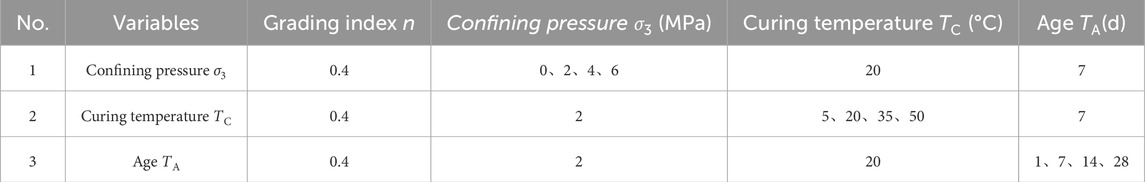
Table 1. Simulation schemes for Slag-Loess-Based cemented backfill material.
2.2 Generation of numerical models
2.2.1 Boundary generation method for aggregate block models
Mechanical experiments use crushed, large-particle aggregates to create cemented backfill. The complex shapes of these aggregates, with their uneven surfaces and sharp edges, significantly affect the fill material’s mechanical properties. Therefore, it is essential to develop a numerical model that closely replicates the actual morphology of the aggregates. This study used CT scanning to create digital 3D models of aggregates with varying particle sizes, extracting and statistically analyzing boundary contour characteristics. The process included:.
(1) Randomly selecting 36 aggregates from the cemented backfill material (Figure 1). Aggregates were cleaned and air-dried to remove surface impurities that could affect scanning results.
(2) Scanning and imaging the selected aggregate blocks using the Nano 3052E CT system (Figure 2). CT slices were reconstructed in 3D using Avizo software to determine contour characteristics.
(3) Selecting typical aggregate contours to form closed polyhedrons with triangular mesh division, saved as STL files, based on the aggregate contour characteristics.
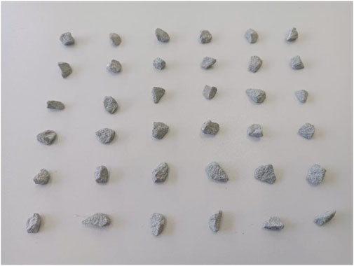
Figure 1. Randomly selected aggregate blocks.
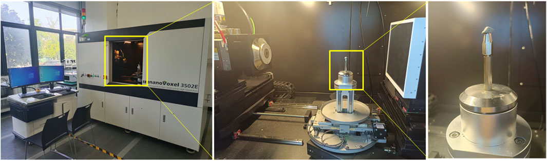
Figure 2. Nano 3052E CT integrated analysis system.
2.2.2 Numerical model development based on the actual shape of aggregates
To accurately represent the realistic morphology of aggregate particles in PFC3D, rigid clumps (Clumps) are used instead of conventional spherical particles. The process is as follows:
(1) Import various closed polyhedrons with triangular mesh divisions (STL files) into PFC3D to create aggregate templates (Figure 3).
(2) Adjust the dimensions of the aggregate block templates to generate aggregate blocks of varying sizes.
(3) Use the Pebble command to fill a designated enclosed space, employing the software’s BubblePack algorithm, to form angular, polyhedral rigid clumps. The “ratio” parameter (ranging from 0 to 1.0) controls the minimum to maximum pebble radii ratio, and the “distance” parameter (ranging from 0 to 180) governs the clump aggregate surface smoothness. For computational efficiency, a ratio of 0.2 and a distance of 140 were selected. The resulting rigid clumps are shown in Figure 4.
(4) Aggregate shape simplification. While the model effectively replicates the statistical shape, size, and distribution of aggregates, fully incorporating aggregate shape is computationally intensive. The high proportion of fine aggregates in cemented backfill materials complicates the creation of a complete aggregate gradation model. Following established research (Chen et al., 2021b; Xue et al., 2020), a 2.36 mm particle size is used to differentiate between coarse and fine aggregates. Considering the limited influence of fine aggregate shape on mechanical properties, particles smaller than 3 mm are modeled as spheres. The shape of aggregates between 3–10 mm is considered, as shown in Figure 5.
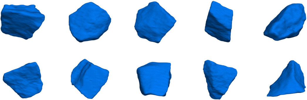
Figure 3. Different templates for aggregates.
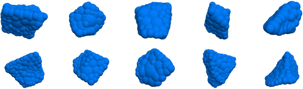
Figure 4. Clumps with different shapes.
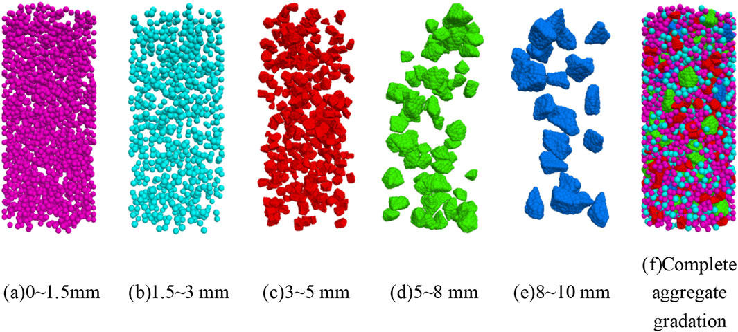
Figure 5. Model of aggregates: (a) 0∼1.5 mm; (b) 1.5∼3 mm; (c) 3∼5 mm; (d) 5∼8 mm; (e) 8∼10 mm; (f) Complete aggregate gradation.
2.2.3 Numerical model feneration for cemented backfill
The Talbot grading index (n) of 0.4, derived from laboratory experiments on optimal aggregate gradation, was used to construct the numerical model. The modeling procedure was as follows: First, boundary walls were created to match the specimen dimensions (50 mm diameter and 100 mm height). The loading rate is 0.5 mm/min. Then, the cemented material and aggregates were generated based on the particle size distribution and volume proportions in Table 2, as illustrated in Figure 6. In the cemented backfill material, cementitious material and aggregate particles are thoroughly mixed to create a material with a degree of fluidity. This implies that each aggregate particle is enveloped by the cementitious material, indicating bonding characteristics at the particle contacts. To balance accuracy and computational feasibility, a parallel bond model was applied to all contacts, including those between cementitious material particles, between cementitious material and aggregate particles, and between aggregate particles. This approach assumes bonding and frictional behavior between all particles. To represent the heterogeneity of the cemented backfill material, all contacts were assumed to follow a Weibull distribution (Huang et al., 2017). The probability density function of theWeibull distribution (Equation 1) is.
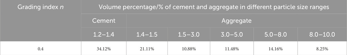
Table 2. Volume proportions of each gradation in the particle flow model of cemented backfill materials when the Talbot index for aggregate particle gradation is 0.4.
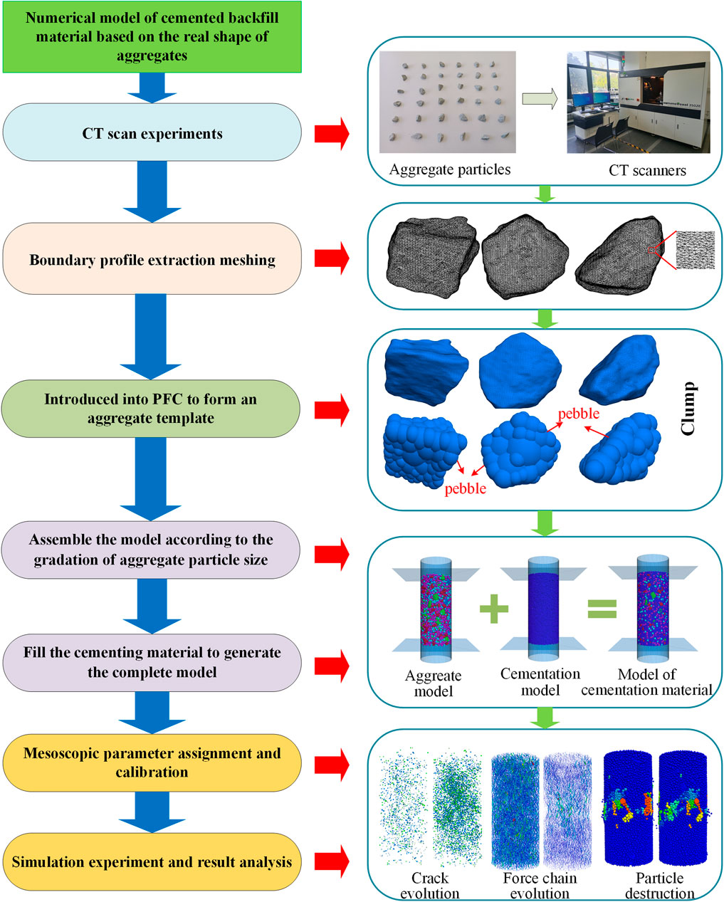
Figure 6. Design of numerical model for cemented backfill materials and analysis framework for mesostructural evolution.
Here, α and β represent the scale and shape parameters, respectively, where x denotes the random variable, which, in this context, refers to the mesoscale parameters. The scale parameter α governs the mean of the mesoscale parameters and is typically set to α = 1. The shape parameter β defines the distribution of the mesoscale parameters; in this section, it is assigned a value of β = 6.
2.3 Calibration of micro-mechanical parameters
A particle flow numerical model was developed to match the specimen’s conditions. Micro-mechanical parameters were assigned to the particles and iteratively calibrated using a trial-and-error approach until the model reached equilibrium. This ensured that the model’s deviatoric stress-strain curve matched the experimental results, completing the parameter calibration before analysis. For example, for cemented backfill materials cured at 20°C for 7 days under varying confining pressures (σ3), the micro-parameters shown in Tables 3 and 4 were applied. The resulting deviatoric stress-strain curves, compared with laboratory data in Figure 7, The comparison of the stress-strain curves obtained from the test and the simulation shows that the root mean square error of the peak strength and peak strain is less than 5%, and the correlation coefficient R2 is greater than 0.95. Confirm that the calibration was successful and accurately reflects the material’s mechanical properties. Micro-parameters for other conditions are also provided in Tables 3 and 4.
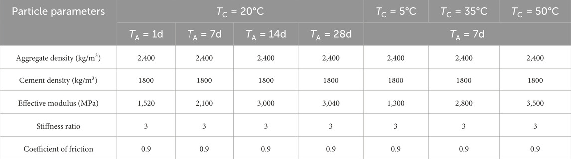
Table 3. Particle parameters of cemented filling materials under different curing temperatures and curing ages.
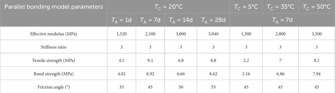
Table 4. Parallel bonding model parameters of cemented filling materials under different curing temperatures and curing ages.
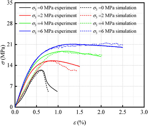
Figure 7. Numerical Stress-strain curves of cemented backfill material under different confining pressures compared with the experimental results.
3 Results and discussions
3.1 Evolution of cemented backfill material
The macroscopic failure of a material is characterized by the formation, growth, and merging of internal cracks. Analyzing crack evolution is essential for evaluating and forecasting material damage and failure. This study examines crack development in cemented backfill under different confining pressures (σ3), curing temperatures (TC), and curing ages (TA) at four key points: crack initiation stress, damage stress, peak stress, and post-peak failure. Crack initiation stress occurs at approximately 30% of the peak stress, while damage stress occurs at about 80% of the peak stress. A FISH function is used to track the status of parallel bond contacts in the numerical model. A broken parallel bond signifies crack initiation, and its location is recorded. Based on the failure mode of the parallel bonds, the resulting cracks are classified as tensile or shear cracks.
Figure 8 illustrates the total number of cracks, the proportion of tensile cracks, and the proportion of shear cracks at various characteristic points in the cemented backfill, under varying confining pressures (σ3), curing temperatures (TC), and curing ages (TA).
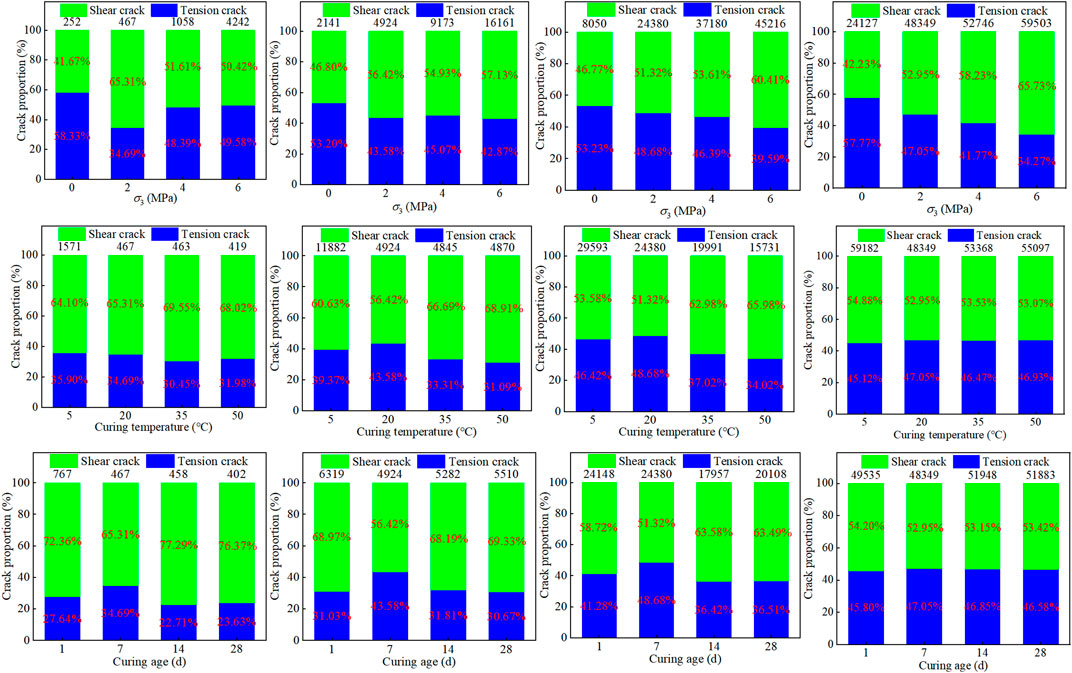
Figure 8. The number and proportion of cracks in the cemented filling material at each characteristic point under different confining pressures σ3, curing temperatures TC, and curing ages TA.
As shown in Figure 8, under identical confining pressure (σ3) conditions, the number of internal cracks within the specimen increased with increasing load, with a significant increase observed after reaching the damage stress. For example, with a confining pressure of σ3 = 2 MPa, the total crack count rose from 467 at the crack initiation stress to 4,924 at the damage stress, an increase of 4,457 cracks. From the damage stress to the peak stress, the total crack count increased by 19,456. The total number of cracks correlated positively with confining pressure σ3 across all loading stages, indicating that higher confining pressures promoted crack initiation and propagation, although the degree of influence varied. At the crack initiation stress, the crack number was 252 at σ3 = 0 MPa, compared to 4,242 at σ3 = 6 MPa, a 15.83-fold increase. At the post-peak failure point, the crack number was 24,127 at σ3 = 0 MPa, and 59,503 at σ3 = 6 MPa, a 1.47-fold increase. Furthermore, at σ3 = 0 MPa, the specimen primarily exhibited tensile cracks at all stages, accounting for 57.77% at failure. However, increasing the confining pressure shifted the dominant crack type from tensile to shear, with tensile cracks accounting for only 34.27% at failure when σ3 = 6 MPa.
The effect of curing temperature, denoted as TC, on crack number is most significant at TC = 5°C prior to specimen failure. At the damage stress point, the total crack count at TC = 5°C is 11,882, whereas the total crack count at other curing temperatures TC, ranges from 4,845 to 4,924. This suggests that lower curing temperatures TC, promote internal crack initiation and propagation under increasing load. Moreover, the proportion of shear cracks decreases with loading across different curing temperatures TC. For instance, at TC = 35°C, the shear crack proportion is 69.55% at the crack initiation stress point, decreasing to 53.53% at the peak stress point. This indicates that internal shear failure dominates the initial loading phase. Although the trend of shear failure diminishes with increasing load, shear failure remains the primary failure mode at each stage, with shear crack proportions exceeding 50% at all tested curing temperatures TC.
Under identical TA conditions, crack numbers within the specimens increased with escalating load. A significant increase in crack numbers was observed upon reaching the damage stress. For example, at TA = 14 days, the total crack count increased from 458 to 5,282 as the load increased from the crack initiation stress to the damage stress, representing an increase of 4,824 cracks. Further load increase from the damage stress to the peak stress resulted in a crack count escalation from 5,282 to 17,927, an addition of 12,675 cracks. Prior to reaching the crack initiation stress, the total crack number exhibited an inverse relationship with TA, indicating that cemented backfill materials at lower TA values demonstrate more active crack initiation and propagation during the initial loading phase. Beyond the crack initiation stress, no discernible correlation was observed between the total crack number and TA. Furthermore, the proportion of shear cracks decreased across all TA values with increasing load. At TA = 14 days, the shear crack proportion was 77.29% at the crack initiation stress, decreasing to 53.15% at the post-peak failure point. This suggests that the internal failure mechanism is primarily shear-dominated during the initial loading stages, with a gradual reduction in shear failure tendency as the load increases, although shear failure remains the dominant mode throughout all loading phases.
The deformation and failure characteristics of cemented backfill are not only influenced by the number of initiated cracks and the ratio of tensile to shear cracks, but also closely related to their spatial distribution. Figure 9 presents the spatial distribution of cracks within cemented backfill at crack initiation stress, damage stress, peak stress, and post-peak failure, under varying confining pressures (σ3), curing temperatures (TC), and curing ages (TA).
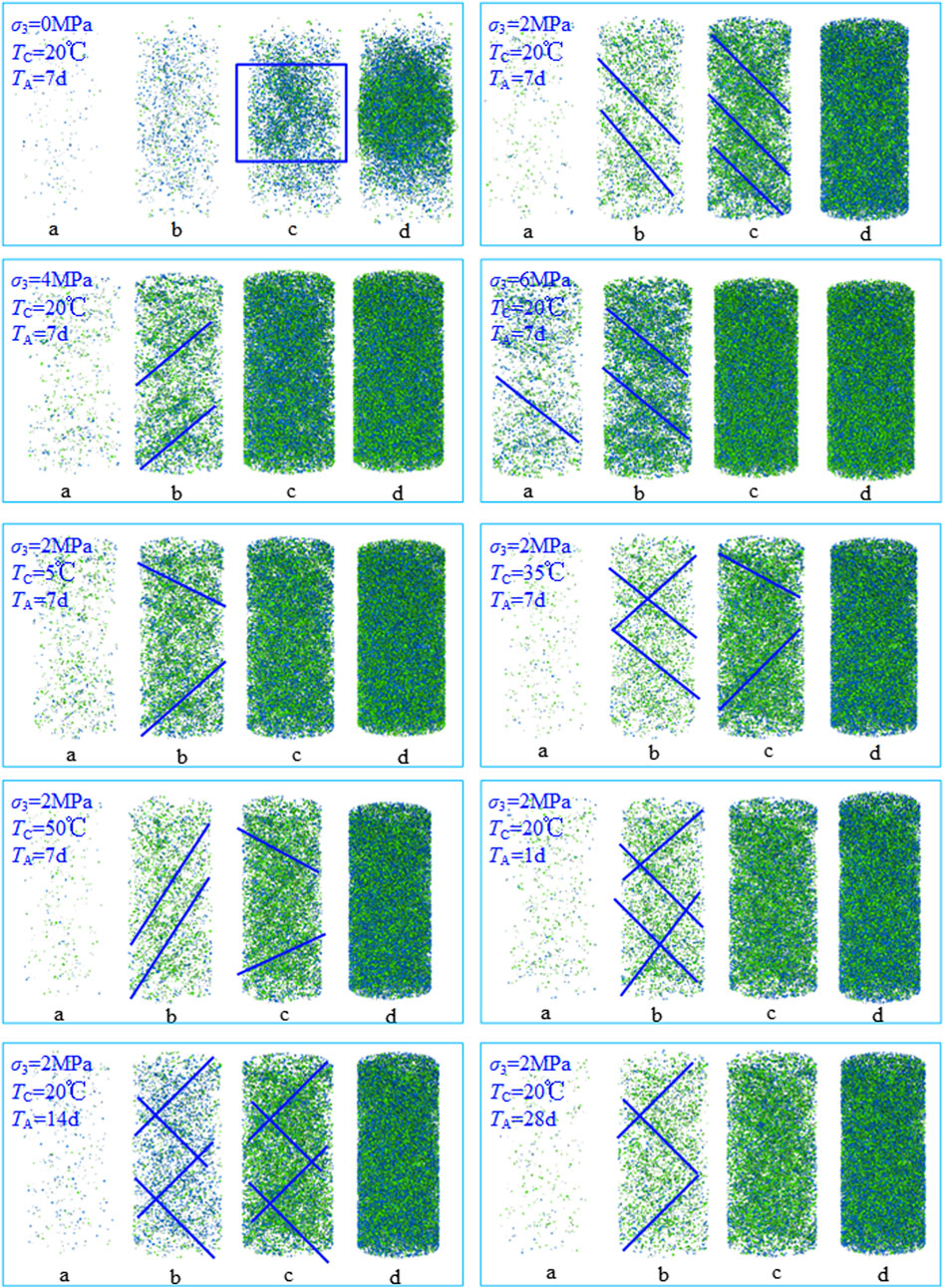
Figure 9. Distribution characteristics of cracks in cemented filling materials at different characteristic points under different confining pressures σ3, curing temperatures TC, and curing ages TA.
As depicted in Figure 9, the spatial distribution of cracks undergoes a significant transformation with increasing confining pressure σ3. The spatial distribution characteristics are not distinct at crack initiation stress due to the relatively sparse crack population. The high crack density at peak stress and post-peak failure complicates distribution pattern analysis; thus, the spatial distribution at damage stress is the primary focus. At σ3 = 0 MPa, the cemented backfill exhibits minimal crack generation and no discernible propagation trend at the damage stress point, with cracks primarily located in the specimen’s central region. At σ3 = 2 MPa, the cemented backfill shows clear crack initiation and propagation at the damage stress point, with cracks propagating from the upper to the central part of the specimen. When σ3 exceeds 4 MPa, crack density further increases, concentrating in the upper and lower sections of the specimen, exhibiting clear crack concentration and a tendency to propagate towards the center. Under high confining pressure, the specimen demonstrates higher strength and a greater number and wider distribution of cracks. This is attributed to the increased confinement with higher σ3, which facilitates a more stable skeletal structure. As the applied load increases, inter-particle contact forces intensify, and the material continues to bear the load through inter-particle friction and crack closure.
The spatial distribution of cracks exhibited a corresponding alteration with increasing curing temperature TC. Specimens of cemented backfill cured at TC = 5°C displayed a high crack density at the damage stress point, with cracks distributed throughout the specimen, demonstrating crack concentration. Compared to the cemented backfill cured at TC = 5°C, specimens cured at TC = 20°C, 35°C, and 50°C showed relatively less crack initiation and propagation at the damage stress point. Crack concentration appeared at the lower portion of the specimens, with a tendency to propagate towards the middle and sides. The effect of curing temperature on crack quantity was more pronounced at lower temperatures (5°C), while this influence diminished as the temperature increased. Moreover, changes in temperature had only a limited impact on the spatial distribution pattern of the cracks.
As the curing age TA, increases, the spatial distribution of cracks undergoes significant changes. At TA = 1 day, the cemented backfill exhibits crack initiation at the damage stress point, indicating unstable crack propagation. At TA = 7 days, cracks are primarily distributed in the upper portion of the specimen at the damage stress point, with a trend toward the middle; crack distribution also begins to appear in the lower portion. At TA = 14 days and 28 days, cracks are mainly concentrated in the middle of the specimen at the damage stress point, exhibiting crack concentration and a tendency to propagate bilaterally. The curing age TA, has minimal effect on the final crack ratio and number, with shear cracks predominating. At TA = 1 day, crack distribution is relatively uniform and dispersed, lacking distinct spatial characteristics. With increasing TA, crack concentration zones gradually appear at the upper and lower ends of the specimen, forming macroscopic shear bands.
3.2 Failure characteristics of particles of cemented backfill material
Figure 10 presents the particle failure modes in cemented backfill subjected to axial rotation at a specific angle, under varying confining pressures (σ3), curing temperatures (TC), and curing ages (TA). The crack count, tensile crack percentage, and shear crack percentage are quantified at key points. In the figure, blue denotes undamaged particles, while red indicates particles experiencing the most severe damage.
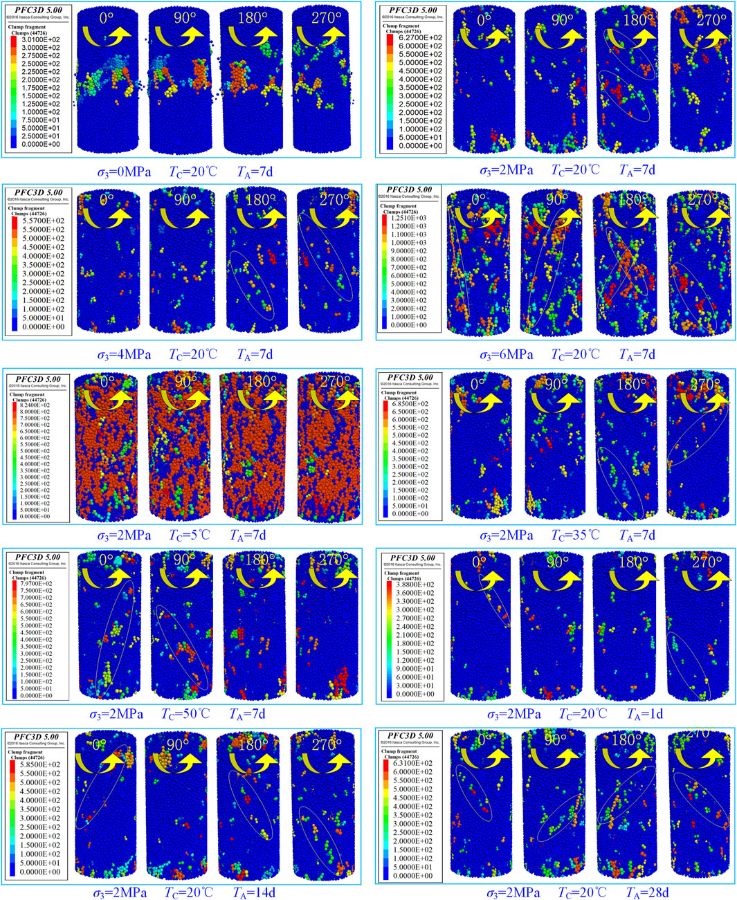
Figure 10. Particle failure modes of cemented filling materials under different confining pressures σ3 curing temperatures TC, and curing ages TA.
Initial particle fracture and slip occur between smaller particles. As the applied load increases, internal crack propagation initiates, and fracture and slip phenomena appear around larger particles. At a confining pressure (σ3) of 0 MPa, particle failure predominantly occurs in the specimen’s midsection, resulting in lateral bulging, localized surface spalling, and the expulsion of partially damaged particles, while the end sections exhibit minimal particle damage. Increasing confining pressure (σ3) intensifies damage at the specimen’s upper and lower ends, with shear failure features becoming more evident. The lateral constraint provided by σ3 enables damaged particles to continue bearing load through inter-particle and crack closure friction. Specimen failure typically depends on the complete penetration of the shear failure surface. Consequently, in conventional triaxial compression tests, shear failure often dominates the specimen’s failure mode. It should be noted that direct shear surfaces are difficult to obtain using the three-dimensional numerical calculation model established by PFC3D; instead, potential shear failure locations within the specimen can only be inferred from particle failure characteristics, as indicated by the yellow ellipses in the figure.
The failure modes of the particles predominantly demonstrate a combination of tensile and shear failure under varying curing temperatures TC. The degree of failure is contingent upon TC. At TC = 5°C, the majority of particles on the specimen surface exhibit failure. With increasing TC, both the number and size of sliding blocks at failure diminish. When TC exceeds 20°C or the curing age surpasses 7 days, significant dilation initiates at the specimen ends. This dilation progressively propagates towards the center, macroscopically forming a shear failure zone with a specific inclination angle.
4 Conclusion
(1) Analysis of the aggregate boundary contour characteristics of cemented backfill materials indicates that the aggregate blocks are predominantly irregular polyhedrons. Representing coarse aggregates (particle size >3 mm) with rigid clumps provides a more realistic depiction of the deformation and failure process in cemented backfill materials.
(2) Increasing confining pressure, σ3, accelerates crack initiation and propagation, and also modifies the spatial distribution of cracks and the ultimate failure mode of the specimens. The total crack count and the proportion of shear cracks correlate positively with σ3, whereas the proportion of tensile cracks correlates negatively with σ3. Under high σ3, the specimens exhibit increased strength, accompanied by a greater number and wider distribution of cracks. At various curing ages TA, the specimens are primarily characterized by shear cracks; an increase in TA has a minor effect on the final proportion and number of tensile-shear cracks. Lower curing temperatures TC (5°C), significantly influence the crack count, with the impact diminishing as TC increases. Furthermore, temperature variations have a minor effect on the spatial distribution of cracks.
(3) Under uniaxial compression, particle failure primarily occurs in the specimen’s central region, characterized by lateral bulging. As confining pressure σ3, increases, tensile failure becomes more pronounced at the specimen’s ends, accompanied by an increased degree of damage. At varying curing temperatures TC, the specimen ends exhibit significant tensile failure. The macroscopic failure mode of the specimens primarily demonstrates shear failure. However, as curing temperature TC, increases, the quantity and scale of damaged particles decrease. With increasing age TA, the trend of shear failure becomes more evident.
Data availability statement
The raw data supporting the conclusions of this article will be made available by the authors, without undue reservation.
Author contributions
TL: Writing – review and editing, Writing – original draft, Resources, Conceptualization, Validation. LC: Methodology, Supervision, Validation, Writing – original draft, Writing – review and editing. PW: Funding acquisition, Validation, Project administration, Writing – original draft, Methodology. KZ: Formal Analysis, Writing – review and editing. LZ: Supervision, Writing – review and editing, Investigation. TJ: Software, Writing – original draft. LF: Writing – original draft, Visualization.
Funding
The author(s) declare that financial support was received for the research and/or publication of this article. This work was supported by the National Natural Science Foundation of China (52274140 and 52304102). Xuzhou Key Research and Development Plan (Social Development), Project Number: KC23314.
Conflict of interest
The authors declare that the research was conducted in the absence of any commercial or financial relationships that could be construed as a potential conflict of interest.
Generative AI statement
The author(s) declare that no Generative AI was used in the creation of this manuscript.
Publisher’s note
All claims expressed in this article are solely those of the authors and do not necessarily represent those of their affiliated organizations, or those of the publisher, the editors and the reviewers. Any product that may be evaluated in this article, or claim that may be made by its manufacturer, is not guaranteed or endorsed by the publisher.
References
Abd-El Aziz, M. A., El Aleem, S. A., and Heikal, M. (2012). Physico-chemical and mechanical characteristics of pozzolanic cement pastes and mortars hydrated at different curing temperatures. Constr. Build. Mater. 26, 310–316. doi:10.1016/j.conbuildmat.2011.06.026
Al-Majidi, M. H., Lampropoulos, A. P., Cundy, A. B., Tsioulou, O. T., and Al-Rekabi, S. (2018). A novel corrosion resistant repair technique for existing reinforced concrete (RC) elements using polyvinyl alcohol fibre reinforced geopolymer concrete (PVAFRGC). Constr. Build. Mater. 164, 603–619. doi:10.1016/j.conbuildmat.2017.12.213
Amran, M., Murali, G., Khalid, N. H. A., Fediuk, R., Ozbakkaloglu, T., Lee, Y. H., et al. (2021). Slag uses in making an ecofriendly and sustainable concrete: a review. Constr. Build. Mater. 272, 121942. doi:10.1016/j.conbuildmat.2020.121942
Arslan, O., Messali, F., Smyrou, E., Bal, İ. E., and Rots, J. G. (2021). Experimental characterization of the axial behavior of traditional masonry wall metal tie connections in cavity walls. Constr. Build. Mater. 266, 121141. doi:10.1016/j.conbuildmat.2020.121141
Bull, A. J., and Fall, M. (2020). Curing temperature dependency of the release of arsenic from cemented paste backfill made with Portland cement. J. Environ. Manag. 269, 110772. doi:10.1016/j.jenvman.2020.110772
Chen, S. M., Wu, A. X., Wang, Y. M., and Wang, W. (2021a). Coupled effects of curing stress and curing temperature on mechanical and physical properties of cemented paste backfill. Constr. Build. Mater. 273, 121746. doi:10.1016/j.conbuildmat.2020.121746
Chen, X., Shi, C., Zhang, Y. L., and Yang, J. X. (2021b). Numerical and experimental study on strain rate effect of ordinary concrete under low strain rate. Ksce J. Civ. Eng. 25, 1790–1805. doi:10.1007/s12205-021-0969-x
Cui, L., and Fall, M. (2016). Mechanical and thermal properties of cemented tailings materials at early ages: influence of initial temperature, curing stress and drainage conditions. Constr. Build. Mater. 125, 553–563. doi:10.1016/j.conbuildmat.2016.08.080
Dassekpo, J. B. M., Feng, W. P., Li, Y. R., Miao, L., Dong, Z., and Ye, J. (2021). Synthesis and characterization of alkali-activated loess and its application as protective coating. Constr. Build. Mater. 282, 122631. doi:10.1016/j.conbuildmat.2021.122631
Delgado, M. C. J., and Guerrero, I. C. (2007). The selection of soils for unstabilised earth building: a normative review. Constr. Build. Mater. 21, 237–251. doi:10.1016/j.conbuildmat.2005.08.006
Ercikdi, B., Cihangir, F., Kesimal, A., Deveci, H., and Alp, İ. (2009a). Utilization of industrial waste products as pozzolanic material in cemented paste backfill of high sulphide mill tailings. J. Hazard. Mater. 168, 848–856. doi:10.1016/j.jhazmat.2009.02.100
Ercikdi, B., Kesimal, A., Cihangir, F., Deveci, H., and Alp, İ. (2009b). Cemented paste backfill of sulphide-rich tailings: importance of binder type and dosage. Cem. and Concr. Compos. 31, 268–274. doi:10.1016/j.cemconcomp.2009.01.008
Escalante-Garcia, J. I., and Sharp, J. H. (2001). The microstructure and mechanical properties of blended cements hydrated at various temperatures. Cem. Concr. Res. 31, 695–702. doi:10.1016/S0008-8846(01)00471-9
Fall, M., Belem, T., Samb, S., and Benzaazoua, M. (2007). Experimental characterization of the stress-strain behaviour of cemented paste backfill in compression. J. Mater. Sci. 42, 3914–3922. doi:10.1007/s10853-006-0403-2
Fall, M., and Samb, S. S. (2009). Effect of high temperature on strength and microstructural properties of cemented paste backfill. Fire Saf. J. 44, 642–651. doi:10.1016/j.firesaf.2008.12.004
Gu, L. Y., Lv, Q. F., Wang, S. H., Xiang, J., Guo, L., and Jiang, J. (2021). Effect of sodium silicate on the properties of loess stabilized with alkali-activated fly ash-based. Constr. Build. Mater. 280, 122515. doi:10.1016/j.conbuildmat.2021.122515
Hanegbi, N., and Katra, I. (2020). A clay-based geopolymer in loess soil stabilization. Appl. Science. Basel. 10, 2608. doi:10.3390/app10072608
He, W., Zheng, C. S., Li, S. H., Shi, W., and Zhao, K. (2021). Strength development monitoring of cemented paste backfill using guided waves. Sensors 21, 8499. doi:10.3390/s21248499
Huang, G. D., Ji, Y. S., Zhang, L. L., Hou, Z., and Wu, S. (2019). Influence of calcium content on structure and strength of MSWI bottom ash-based geopolymer. Mag. Concr. Res. 71, 362–372. doi:10.1680/jmacr.17.00542
Huang, S., Xia, K. W., and Qiao, L. (2011). Dynamic tests of cemented paste backfill: effects of strain rate, curing time, and cement content on compressive strength. J. Mater. Sci. 46, 5165–5170. doi:10.1007/s10853-011-5449-0
Huang, Y. H., Yang, S. Q., Ranjith, P. G., and Zhao, J. (2017). Strength failure behavior and crack evolution mechanism of granite containing pre-existing non-coplanar holes: experimental study and particle flow modeling. Comput. Geotechnics 88, 182–198. doi:10.1016/j.compgeo.2017.03.015
Jafari, M., Shahsavari, M., and Grabinsky, M. (2020). Experimental study of the behavior of cemented paste backfill under high isotropic compression. J. Geotech. Geoenvir. Eng. 146. doi:10.1061/(ASCE)GT.1943-5606.0002383
Jiang, H. G., Fall, M., and Cui, L. (2016). Yield stress of cemented paste backfill in sub-zero environments: experimental results. Miner. Eng. 92, 141–150. doi:10.1016/j.mineng.2016.03.014
Jiang, H. Q., Fall, M., and Cui, L. (2017). Freezing behaviour of cemented paste backfill material in column experiments. Constr. Build. Mater. 147, 837–846. doi:10.1016/j.conbuildmat.2017.05.002
Jiang, H. Q., Ren, L., Zhang, Q., Zheng, J., and Cui, L. (2022a). Strength and microstructural evolution of alkali-activated slag-based cemented paste backfill: coupled effects of activator composition and temperature. Powder. Technol. 401, 117322. doi:10.1016/j.powtec.2022.117322
Li, J., Zhang, J., Yang, X., Zhang, A., and Yu, M. (2023). Monte Carlo simulations of deformation behaviour of unbound granular materials based on a real aggregate library. Int. J. Pavement Eng. 24 (1), 2165650. doi:10.1080/10298436.2023.2165650
Luo, Y., Huang, J., Si, X., Lin, F., and Wu, W. (2025). An energy-based method for uniaxially compressed rocks and its implication. J. Rock Mech. Geotechnical Eng. 17 (3), 1429–1444. doi:10.1016/j.jrmge.2024.07.002
Lv, H. Y., Chen, Y. L., Xie, Q. H., Wu, P., Chen, Y., Gu, J., et al. (2022). Performance optimization and characterization of loess-slag-based geopolymer composite: a new sustainable green material for backfill. Constr. Build. Mater. 354, 129103. doi:10.1016/j.conbuildmat.2022.129103
Nadoushan, M. J., and Ramezanianpour, A. A. (2016). The effect of type and concentration of activators on flowability and compressive strength of natural pozzolan and slag-based geopolymers. Constr. Build. Mater. 111, 337–347. doi:10.1016/j.conbuildmat.2016.02.086
Narmluk, M., and Nawa, T. (2011). Effect of fly ash on the kinetics of Portland cement hydration at different curing temperatures. Cem. Concr. Res. 41, 579–589. doi:10.1016/j.cemconres.2011.02.005
Nasir, O., and Fall, M. (2009). Modeling the heat development in hydrating CPB structures. Comput. Geotech. 36, 1207–1218. doi:10.1016/j.compgeo.2009.05.008
Oner, A., Akyuz, S., and Yildiz, R. (2005). An experimental study on strength development of concrete containing fly ash and optimum usage of fly ash in concrete. Cem. Concr. Res. 35, 1165–1171. doi:10.1016/j.cemconres.2004.09.031
Paul, M., and Glasser, F. P. (2000). Impact of prolonged warm (85°C) moist cure on Portland cement paste. Cem. Concr. Res. 30, 1869–1877. doi:10.1016/S0008-8846(00)00286-6
Peyronnard, O., and Benzaazoua, M. (2011). Estimation of the cementitious properties of various industrial by-products for applications requiring low mechanical strength. Resour. Conser. Recycl. 56, 22–33. doi:10.1016/j.resconrec.2011.08.008
Pokharel, M., and Fall, M. (2013). Combined influence of sulphate and temperature on the saturated hydraulic conductivity of hardened cemented paste backfill. Cem. Concr. Compos. 38, 21–28. doi:10.1016/j.cemconcomp.2013.03.015
Qaidi, S., Tayeh, B. A. F., Isleem, H. F., de Azevedo, A. R., Ahmed, H. U., and Emad, W. (2022). RETRACTED: sustainable utilization of red mud waste (bauxite residue) and slag for the production of geopolymer composites: a review. CASE Stud. Constr. Mater. 16, e00994. doi:10.1016/j.cscm.2022.e00994
Shi, H., Chen, W., Zhang, H., Song, L., Li, M., Wang, M., et al. (2023). Dynamic strength characteristics of fractured rock mass. Eng. Fract. Mech. 292, 109678. doi:10.1016/j.engfracmech.2023.109678
Shi, H., Zhang, H., Chen, W., Song, L., and Li, M. (2024). Pull-out debonding characteristics of rockbolt with prefabricated cracks in rock: a numerical study based on particle flow code. Comput. Part. Mech. 11 (1), 29–53. doi:10.1007/s40571-023-00607-9
Si, X., Zhang, Z., Li, X., Yi, G., Luo, Y., Tan, L., et al. (2025). Influences of maximum principal stress direction and cross-section shape on tunnel stability. J. Rock Mech. Geotechnical Eng. 17 (4), 2159–2180. doi:10.1016/j.jrmge.2024.10.003
Wang, Y., Fall, M., and Wu, A. X. (2016). Initial temperature-dependence of strength development and self-desiccation in cemented paste backfill that contains sodium silicate. Cem. and Concr. Compos. 67, 101–110. doi:10.1016/j.cemconcomp.2016.01.005
Wu, J., Jing, H., Gao, Y., Meng, Q., Yin, Q., and Du, Y. (2022). Effects of carbon nanotube dosage and aggregate size distribution on mechanical property and microstructure of cemented rockfill. Cem. Concr. Compos. 127, 104408. doi:10.1016/j.cemconcomp.2022.104408
Wu, J., Wong, H. S., Zhang, H., Yin, Q., Jing, H., and Ma, D. (2024). Improvement of cemented rockfill by premixing low-alkalinity activator and fly ash for recycling gangue and partially replacing cement. Cem. Concr. Compos. 145, 105345. doi:10.1016/j.cemconcomp.2023.105345
Wu, J., Yang, S., Williamson, M., Wong, H. S., Bhudia, T., Pu, H., et al. (2025a). Microscopic mechanism of cellulose nanofibers modified cemented gangue backfill materials. Adv. Compos. Hybrid Mater. 8 (2), 177. doi:10.1007/s42114-025-01270-9
Wu, J., Yang, S., Wong, H. S., Yin, Q., Zhang, H., Chen, W., et al. (2025b). Reinforcement mechanisms of cellulose nanofibers on cemented rockfill: macroscopic, microscopic and molecular insights. Constr. Build. Mater. 466, 140192. doi:10.1016/j.conbuildmat.2025.140192
Wu, W., Xu, W. B., and Zuo, J. P. (2021). Effect of inclined interface angle on shear strength and deformation response of cemented paste backfill-rock under triaxial compression. Constr. Build. Mater. 279, 122478. doi:10.1016/j.conbuildmat.2021.122478
Xu, W. B., Zhang, Y. L., and Liu, B. (2020b). Influence of silica fume and low curing temperature on mechanical property of cemented paste backfill. Constr. Build. Mater. 254, 119305. doi:10.1016/j.conbuildmat.2020.119305
Xu, W. B., Liu, B., and Wu, W. L. (2020a). Strength and deformation behaviors of cemented tailings backfill under triaxial compression. J. CENTRAL SOUTH Univ. 27, 3531–3543. doi:10.1007/s11771-020-4568-7
Xue, B., Pei, J. Z., Zhou, B. C., Zhang, J., Li, R., and Guo, F. (2020). Using random heterogeneous DEM model to simulate the SCB fracture behavior of asphalt concrete. Constr. Build. Mater. 236, 117580. doi:10.1016/j.conbuildmat.2019.117580
Yang, L., Xu, W. B., Yilmaz, E., Wang, Q., and Qiu, J. (2020). A combined experimental and numerical study on the triaxial and dynamic compression behavior of cemented tailings backfill. Eng. Struct. 219, 110957. doi:10.1016/j.engstruct.2020.110957
Yao, Y., Li, J., Ni, J., Liang, C., and Zhang, A. (2022). Effects of gravel content and shape on shear behaviour of soil-rock mixture: experiment and DEM modelling. Comput. Geotechnics 141, 104476. doi:10.1016/j.compgeo.2021.104476
Keywords: slag-loess based materials, cemented backfill materials, mesoscale mechanics, backfill mining, numerical simulation
Citation: Liu T, Chen L, Wu P, Zhang K, Zhang L, Jiang T and Fu L (2025) Numerical simulation study on mesoscopic mechanism of fracture evolution of slag-loess-based cemented backfill material. Front. Mater. 12:1646233. doi: 10.3389/fmats.2025.1646233
Received: 13 June 2025; Accepted: 09 July 2025;
Published: 21 July 2025.
Edited by:
Hao Shi, Anhui University of Science and Technology, ChinaCopyright © 2025 Liu, Chen, Wu, Zhang, Zhang, Jiang and Fu. This is an open-access article distributed under the terms of the Creative Commons Attribution License (CC BY). The use, distribution or reproduction in other forums is permitted, provided the original author(s) and the copyright owner(s) are credited and that the original publication in this journal is cited, in accordance with accepted academic practice. No use, distribution or reproduction is permitted which does not comply with these terms.
*Correspondence: Liang Chen, Y2hlbmxpYW5nNjYxN0BjdW10LmVkdS5jbg==; Peng Wu, cGVuZ3dAeHppdC5lZHUuY24=