- 1School of Mechanical and Electrical Engineering, Lishui Vocational and Technical College, Lishui, China
- 2State Key Laboratory of Precision Manufacturing for Extreme Service Performance, Central South University, Changsha, China
- 3School of Engineering, Lishui University, Lishui, China
- 4Zhejiang BSB Electrical Appliance Co., Ltd, Lishui, China
- 5State Grid Zhejiang Lishui Power Supply Company, Lishui, China
- 6Zhejiang Shuolang Motor Parts Co., Ltd, Lishui, China
- 7Zhejiang Chuangxin Auto Air Conditioner Co., Ltd, Lishui, China
- 8College of Mechanical Engineering, Zhejiang University of Technology, Hangzhou, China
This study investigates the rheological properties of shear-thickening polishing fluids with varying compositions using rheometric analysis. The results reveal a significant correlation between the fluid’s rheological behavior and the mass fraction of the dispersant phase, identifying an optimal mass fraction of 40 wt%. Further experiments, conducted using a customized metallographic grinding machine, systematically analyze the influence of key process parameters. The investigation demonstrates that a lapping duration of 30 min and a polishing duration of 45 min yield optimal performance. Additionally, external pressure experiments indicate that both material removal rate and surface roughness increase with applied pressure, reaching a plateau due to reduced fluid flow and enhanced abrasive penetration, with an optimal pressure of 150 kPa. Furthermore, experiments with varying abrasive particle sizes show that material removal rate and surface roughness increase with larger particles, with an optimal size of 3 μm. In summary, this study establishes the optimal parameters for the integrated shear-thickening assisted abrasive lapping and polishing process: an abrasive particle size of 3 μm, a polishing pressure of 150 kPa, a lapping time of 30 min at 200 rpm, and a polishing time of 45 min at 100 rpm. The implementation of these optimized parameters achieves a surface roughness of 9.7 nm on SiC ceramic substrates, demonstrating the effectiveness of this advanced processing technique.
Introduction
With the advancement of technology, various advanced manufacturing techniques, such as additive manufacturing and precision machining technologies, are playing increasingly important roles in modern industry (Ji et al., 2024; Shen et al., 2024; Yang et al., 2024a; Yang et al., 2024b). The demand for advanced materials with exceptional mechanical properties has surged in recent years, particularly in sectors such as aerospace, automotive, and electronics. Among these advanced materials, silicon carbide (SiC) ceramics stand out due to their remarkable hardness, thermal stability, and corrosion resistance. These properties make SiC ceramics particularly suitable for high-performance applications, including semiconductor devices, cutting tools, and wear-resistant components (Qi et al., 2022b). However, the manufacturing processes associated with hard brittle materials, particularly lapping and polishing, pose significant challenges. Traditional abrasive methods often lead to suboptimal surface finishes, high tool wear rates, and lengthy processing times. However, some non-traditional abrasive methods have been proposed and explored to overcome these issues (Tan et al., 2023; Chen et al., 2024; Ge et al., 2024; Wang et al., 2024). Therefore, the development of innovative techniques to enhance the lapping and polishing of SiC ceramics is imperative to meet the growing demands of industry.
Abrasive machining technology is one of the promising advanced manufacturing technologies for the precision machining process (Zhang et al., 2020; Zhao et al., 2020; Qi et al., 2021a; 2021b; 2022a), especially for the complicated surface finish, and the related numerical and experimental studies have been conducted to improve its machining quality and efficiency (Qi et al., 2017; Zhang et al., 2018; Li et al., 2019; 2021; Chen et al., 2023). One promising avenue of exploration in this regard is the utilization of shear-thickening fluids to assist in the abrasive lapping and polishing processes (Wu et al., 2024; Chen et al., 2025). Shear-thickening fluids are non-Newtonian fluids that exhibit an increase in viscosity with the application of shear stress. This unique behavior allows shear-thickening fluids to provide varying degrees of viscosity, which can be manipulated to optimize the polishing process (Zhou et al., 2024). When incorporated into abrasive slurries, shear-thickening fluids can significantly improve the effectiveness of the lapping process by adapting to the forces applied during machining, thereby enhancing material removal rates and improving surface finishes (Yuan et al., 2024). The concept of using shear-thickening fluids in abrasive machining processes is still relatively novel, and research in this area is limited. Previous studies have demonstrated that shear-thickening fluids can enhance machining performance in various contexts, such as metal cutting and grinding, but there remains a gap in knowledge regarding their application in the lapping and polishing of hard ceramics like SiC. Understanding the interaction between shear-thickening fluids and abrasive particles can lead to improved material removal mechanisms and better control over surface finish.
Li and Xie (2022) investigated an ultra-precision machining method called Green Chemical Jumping Thickening Polishing to improve the surface accuracy of SiC ceramics. They found that when the size of the dispersed phase closely matched the abrasive particle size, the polishing results were optimal. This method was able to reduce the surface roughness of SiC ceramics from an initial Ra of 768 nm to Ra of 32 nm, with subsurface damage ranging between 2.5 μm and 4.5 μm. Lyu et al. (2020) analyzed three key parameters, namely polishing speed, diamond abrasive particle size, and diamond abrasive concentration, in the shear-thickening polishing process to achieve efficient polishing of black lithium tantalate substrates. Their study found that after 4 min of polishing, the surface roughness of the black lithium tantalate substrate dramatically decreased from Ra/Rz 2005/1,374.6 nm to 4.2/22.1 nm, without embedded abrasive particles on the surface. Additionally, during experiments using the shear-thickening polishing setup, it was discovered that centrifugal force affected the distribution of abrasive particles in the polishing fluid, presenting a challenge that needs to be addressed. Zhou et al. (2021) developed a magnetic field-enhanced shear-thickening polishing technique. They analyzed the microscopic material removal mechanism and investigated the rheological properties of the magnetic shear-thickening polishing fluid. A predictive model for material removal rate was established based on the Preston equation, non-Newtonian fluid hydrodynamics, and magnetorheological polishing theory, with a maximum relative error of 7.56%. The effects of polishing head rotation speed, abrasive concentration, and carbonyl iron powder concentration on the material removal function were studied, and the model’s stability was verified. After polishing a zirconia workpiece for 20 min, a low-damage processed surface with a surface roughness of 8.3 nm was achieved. The study confirmed the feasibility of using magnetic field-enhanced shear-thickening polishing for ultra-precision machining of hard and brittle materials like ceramics.
According to the above analysis, unlike prior STP techniques requiring fixed gaps between rollers/grinding wheels and workpieces to generate shear thickening, this study eliminates hardware constraints by achieving viscosity modulation through speed transitions in a standardized metallographic machine. Further, contrary to monophasic STP methods (e.g., Lyu et al.‘s 4-min polishing), this work exploits shear-rate-dependent viscosity shifts: lapping at 200 rpm initiates quasi-solid behavior for aggressive peak removal, while polishing at 100 rpm exploits liquid-like flow for nanoscale refinement-enabling a two-stage synergy unachievable in static-gap systems. Whereas prior STP studies focused on isolated parameters (e.g., abrasive size in Lyu et al.), this work establishes interdependent optima for dispersant concentration, pressure, time, and abrasive size, resolving trade-offs between material removal rate and surface roughness.
In summary, shear-thickening polishing is typically achieved by creating a high relative shear rate between a roller, grinding wheel, or similar tool and the workpiece with a small gap in between, inducing the shear-thickening effect. Alternatively, the shear-thickening polishing fluid itself can flow at a certain velocity over the rough surface of the workpiece, generating a relative shear rate, which triggers the shear-thickening effect. Simultaneously, the polishing fluid produces dynamic pressure on the rough peaks of the workpiece, effectively removing them. Thus, this paper introduces an integrated shear-thickening planar lapping and polishing method and the corresponding polishing disc used to achieve this process. Experimental studies are conducted to verify the feasibility of this method and the usability of the integrated polishing disc.
Experimental work
Preparation of shear-thickening polishing fluid
Shear-thickening polishing fluid is primarily composed of a shear-thickening phase, deionized water, and abrasive particles, mixed and ultrasonically dispersed with the addition of a dispersant. The rheological characteristics of the dispersing phase and abrasive particles vary with different mass fractions. The thickening effect of shear-thickening polishing fluid is mainly achieved by altering the shear rate. Prior to reaching the critical shear rate, the polishing fluid remains in a liquid state. However, once the shear rate surpasses the critical threshold, shear-thickening occurs, transforming the polishing fluid into a quasi-solid state. Therefore, before conducting grinding and polishing experiments, it is necessary to determine the rheological properties of polishing base fluids and polishing fluids of different compositions and ascertain the critical shear rate.
From the analysis of the references, it is evident that the rheological characteristics of corn starch suspension are most suitable for the formulation of shear-thickening polishing fluid. This suspension exhibits insensitivity to changes in shear rate and can achieve the highest viscosity among the non-Newtonian power-law fluids mentioned in the introduction. In the integrated grinding and polishing process studied in this paper, the grinding stage requires high speeds to provide the shear-thickening polishing fluid with high shear rates, inducing shear-thickening phenomena. High speeds also enhance material removal rates, while necessitating a high-viscosity polishing base fluid to retain the abrasive particles for efficient grinding. Therefore, corn starch suspension is well-suited as the polishing base fluid for the shear-thickening polishing fluid used in the integrated shear-thickening lapping and polishing process discussed in this paper.
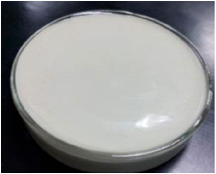
The preparation process of shear-thickening polishing fluid involves mixing shear-thickening components, namely corn starch particles, deionized water, and abrasive particles. After allowing the corn starch particles to fully dissolve in the deionized water, additional corn starch is gradually added until the volume fraction of corn starch meets the experimental requirement. Subsequently, the prepared shear-thickening fluid undergoes ultrasonic dispersion, followed by the addition of a dispersant. With these steps completed, the preparation of shear-thickening polishing fluid is finalized. As shown in Figure 1, the prepared shear-thickening polishing fluid consists of 14 μm corn starch particles as the shear-thickening component, 6 μm diamond abrasive particles, with corn starch mass fraction at 40 wt%, and abrasive particle mass fraction at 20 wt%.
The shear rheological tests of shear-thickening polishing fluid and polishing base fluid were conducted using the Anton Paar MCR302 rotational rheometer in Austria. PP20 plate fixtures and a 20 mm diameter rotor were employed for the tests, with a 1 mm gap between them. The shear rate varied within the range of 0.5–2000 s-1. Analysis of the shear-thickening base fluid rheological curves (see Figure 2) at different concentrations of corn starch revealed that a higher mass fraction of shear-thickening component led to a higher initial viscosity of shear-thickening polishing base fluid. Shear-thickening polishing base fluid with a mass fraction of 35% corn starch exhibited poor rheological characteristics and did not show a distinct viscosity jump. On the other hand, shear-thickening polishing with mass fractions of 40 wt% and 45 wt% corn starch demonstrated better rheological properties with evident viscosity jumps. However, due to the excessively high initial and maximum viscosity of the 35% corn starch, it was not conducive to the relative motion between the workpiece and polishing pad. Therefore, 40 wt% corn starch was selected as the shear-thickening polishing base fluid for subsequent experiments.
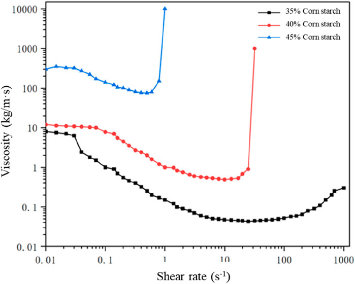
Figure 2. Relationship between the mass fraction of the dispersed phase and the viscosity of the polishing base fluid.
Experimental setup
The integrated shear-thickening assisted abrasive lapping and polishing machining setup, as depicted in Figure 3, comprises the main body of the Chuanhe Smoothneer-6 metallographic lapping and polishing machine. Its lapping baseplate is detachable, with the polishing disc primarily connected to the main baseplate of the metallographic lapping and polishing machine using internal hexagon cylindrical screws. PVC and polyurethane bonded polishing pads are fixed onto the polishing disc using internal hexagon cylindrical screws. Directly above the polishing disc is the workpiece fixture provided by the metallographic lapping and polishing machine. During lapping experiments, the rotation speed of the upper and lower discs, pressure, and polishing time can be adjusted via the touchscreen interface. Figure 4 presents SEM images of different types of polishing pads, wherein both polyurethane and damping cloth polishing pads exhibit a micro-porous structure on their surfaces. As shown in Figures 4a,b, the hole diameters on the polyurethane polishing pad are mostly around 100 μm, while those on the damping cloth polishing pad are primarily around 50 μm, significantly smaller than those on the polyurethane polishing pad. Figure 4c illustrates the surface morphology of the synthetic leather polishing pad, mainly composed of numerous fiber structures with a diameter of approximately 50 μm. Overall, the polyurethane polishing pad features larger holes, thereby exhibiting the strongest capability to retain polishing fluid. For the shear-thickening lapping and polishing process, the ability of the polishing pad to retain fluid is crucial. Under high pressure conditions, the polyurethane polishing pad with strong fluid retention capacity can effectively remove material from the workpiece.
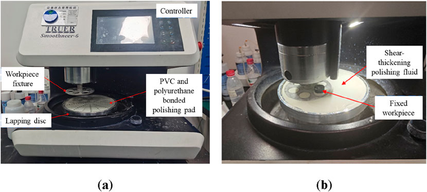
Figure 3. Experimental setup: (a) Chuanhe Smoothneer-6 metallographic lapping and polishing machine, and (b) workpiece and shear-thickening polishing fluid.

Figure 4. SEM images of different types of polishing pad surfaces: (a) polyurethane polishing pad, (b) damping cloth polishing pad, and (c) synthetic leather polishing pad.
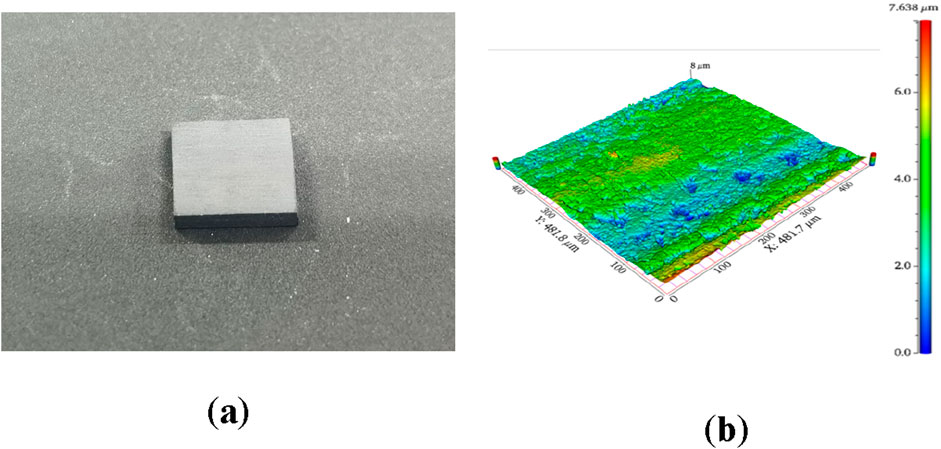
The mechanical properties of the SiC ceramic workpieces processed in this study are presented in Table 1. Initially, SiC ceramic slices with a thickness of 2 mm were obtained by wire cutting, resulting in square pieces with a side length of 10 mm. Subsequently, these pieces underwent uniform grinding using 400# diamond polishing films to achieve a certain level of accuracy and surface quality. The surface roughness ranged from 401 nm to 452 nm. Figure 5a depicts the SiC ceramic square piece after grinding with polishing film, while Figure 5b illustrates the initial surface morphology of the SiC ceramic square piece before grinding. The highest peak on the workpiece surface measures 7.638 μm, with numerous pits present on the surface.
Results and discussion
Effect of processing time on the surface quality in the lapping and polishing stages
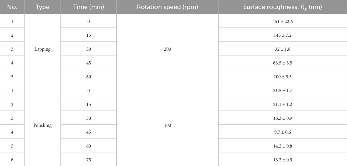
The shear-thickening lapping and polishing integrated processing method enhances the abrasive fluid’s gripping force on abrasive particles by inducing shear thickening effects when the shear rate exceeds a critical threshold, facilitating material removal with minimal surface damage. Experimental design separates lapping and polishing into distinct stages, varying speeds to differentiate between them. At 200 rpm, the relative shear rate surpasses the critical threshold, triggering shear thickening in the abrasive fluid. This stage, termed lapping, involves the shear-thickening base fluid removing surface peaks from SiC ceramic workpieces using diamond abrasives. As speed decreases to 100 rpm, the relative shear rate falls below the critical threshold, reducing viscosity akin to free abrasive polishing. However, the fluid’s viscosity remains higher than typical water-based polishing fluids, providing some grip on diamond abrasives, defining this phase as polishing. Lapping experiments at 200 rpm reveal plowing phenomena, while polishing experiments at 100 rpm show over-polishing occurrences, as shown in Table 2. For each experimental condition the experiment was repeated for 5 times and the average data was taken for further analysis.
It can be seen from Table 2 that during the experiment investigating the impact of lapping time on the surface roughness of SiC ceramic workpieces, the initial roughness was 451 nm. After 15 min of grinding, the surface roughness significantly decreased to 143 nm. Subsequently, with increasing lapping time, the surface roughness continued to decrease to a minimum of 32 nm. However, after 30 min of lapping, the surface roughness began to increase, reaching 100 nm after 60 min of lapping. This phenomenon suggests that during the integrated lapping and polishing stage of the process, plowing occurred on the workpiece surface at 30 min, leading to a significant increase in surface roughness. Therefore, during the integrated lapping and polishing stage, the processing time should be controlled within 30 min to prevent plowing phenomena. Moreover, During the experiment investigating the impact of polishing time on the surface roughness during integrated lapping and polishing, the surface roughness of the workpiece decreased from 31.5 nm to 9.7 nm after polishing at 100 rpm for 45 min. However, as the polishing continued, the roughness began to increase, indicating an over-polishing phenomenon occurring on the workpiece.
To be specific, as the lapping process progresses, the workpiece surface gradually smoothens, with the highest point of surface peaks decreasing from 7.638 μm to 3.725 μm. However, after 30 min, the highest point gradually increases to 7.542 μm, with visible scratches on the surface. The surface morphology of the workpiece after different processing times in the lapping stage is shown in Figure 6. As the polishing process continues, the highest point on the workpiece surface decreases from 338.5 nm to 299.6 nm after 45 min of processing. However, after an additional 30 min of processing, the highest point gradually increases to 387.5 nm, as shown in Figure 7.
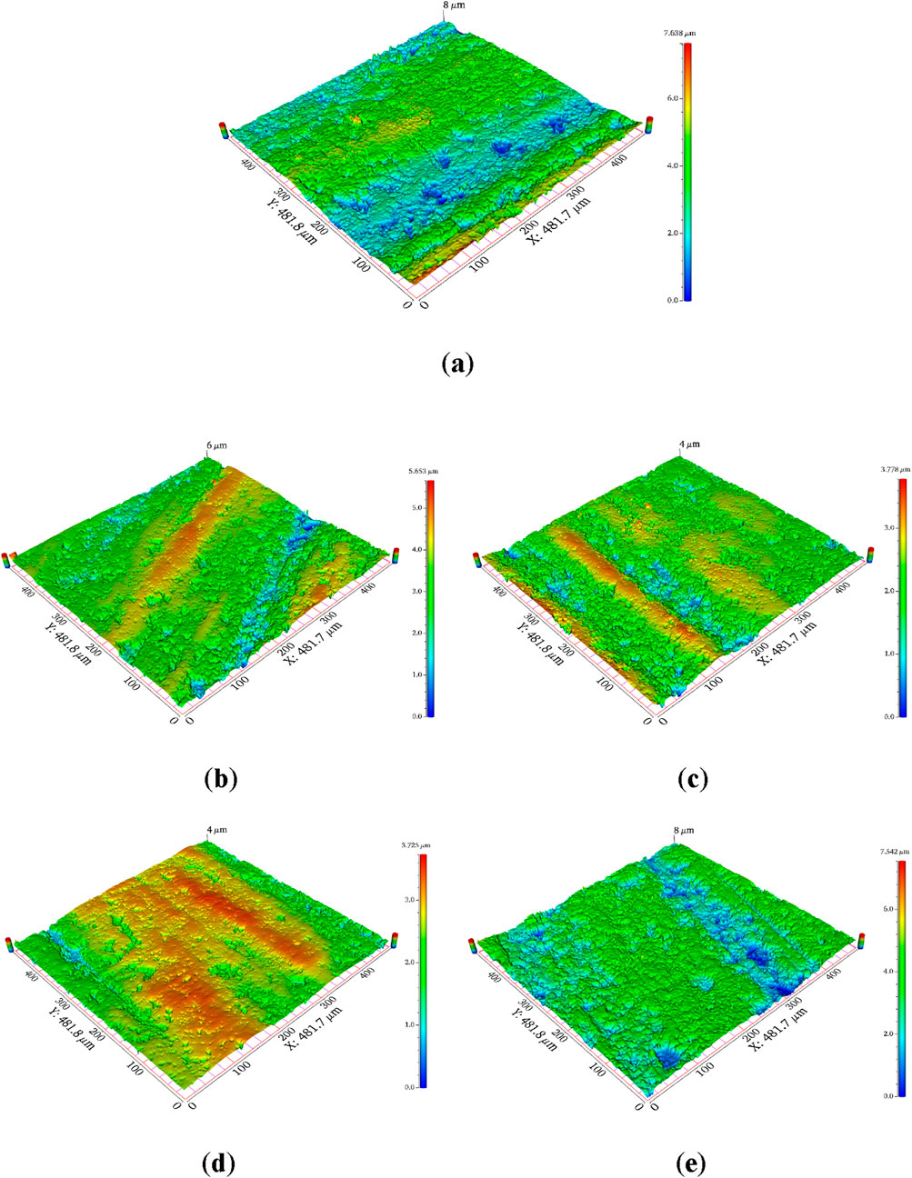
Figure 6. The surface morphology of the workpiece after different processing times in the lapping stage: (a) original surface, (b) 15 min, (c) 30 min, (d) 45 min, (e) 60 min.
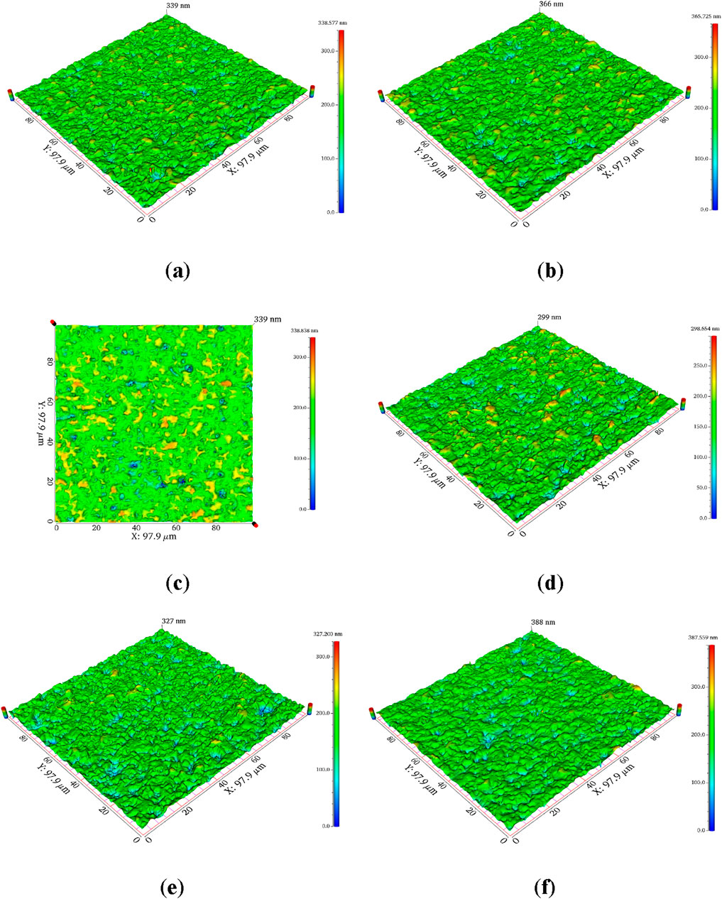
Figure 7. The surface morphology of the workpiece after different processing times in the polishing stage: (a) original surface, (b) 15 min, (c) 30 min, (d) 45 min, (e) 60 min, (f) 75 min.
Effect of pressure on the surface quality in the lapping stage
Since the lapping stage demands high material removal rates, experiments were solely conducted during this stage. Utilizing abrasive particles with a size of 1 μm and a concentration of 25 wt%, four experimental groups were conducted on the workpiece at 200 rpm. Surface morphology observations and material removal rate calculations were performed, as shown in Table 3. For each experimental condition the experiment was repeated for 5 times and the average data was taken for further analysis.

Table 3. Effect of pressure on the materials removal rate and surface roughness in the lapping stage.
As shown in Table 3, in experiments investigating the effects of pressure on material removal rates and surface roughness during the lapping stage of integrated lapping-polishing processes, both material removal rates and surface roughness increase with increasing pressure. However, as the pressure reaches a certain threshold, the rate of increase in both material removal rates and surface roughness slows down. This phenomenon occurs because as the pressure increases, the gap between the workpiece’s bottom surface and the polishing pad gradually decreases. Consequently, the shear-thickening polishing fluid passing through this gap also decreases. Although the polyurethane polishing pad surface provides space for the polishing fluid to reside, its contribution to material removal rates diminishes under high pressure. Thus, a plateau phase exists in the graph where the material removal rate no longer increases. Regarding surface roughness, increased pressure results in decreased flowability of the polishing fluid, causing abrasive particles to produce deeper scratches on the bottom surface of the workpiece. Figure 8 shows the surface morphology of the workpiece after 30 min of lapping at different pressures reveals a continuous increase in the highest point on the workpiece surface as the pressure gradually increases. This elevation rises from 3.725 μm to 6.138 μm.
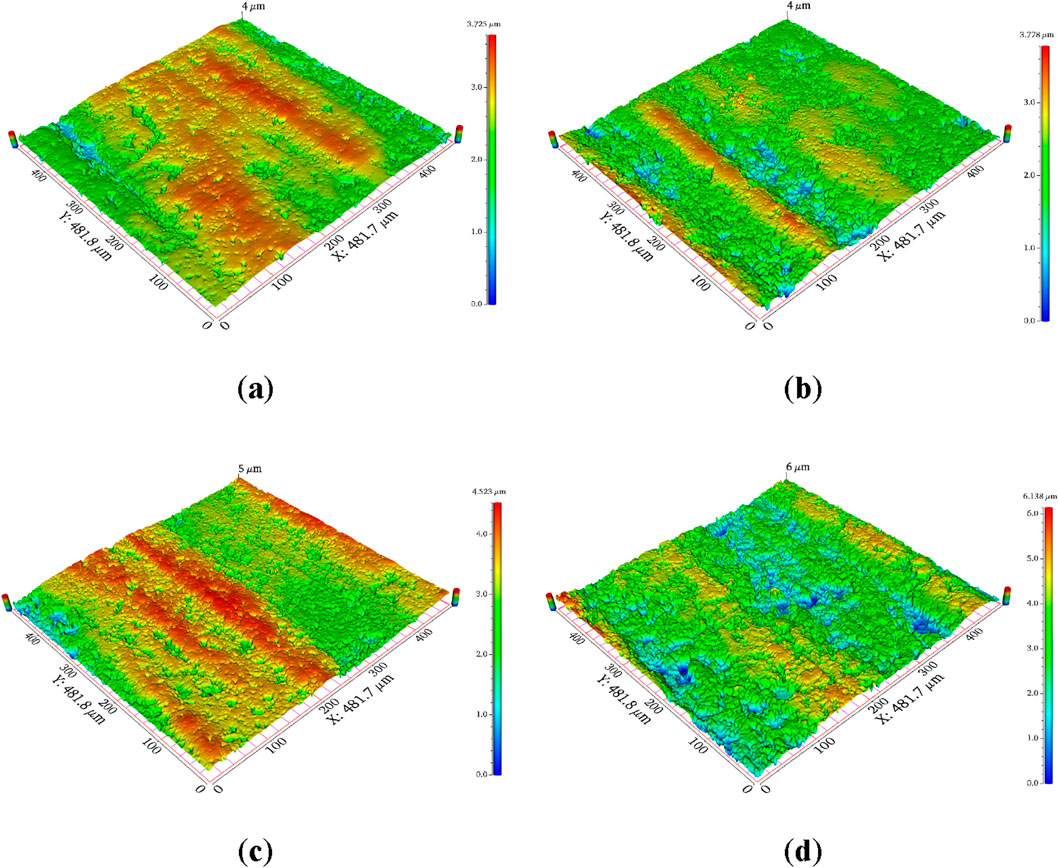
Figure 8. The surface morphology of the workpiece after 30 min of processing under different pressures in the lapping stage: (a) 150 kPa, (b) 300 kPa, (c) 450 kPa, (d) 600 kPa.
Effect of abrasive particle size on the surface quality in the lapping and polishing stages
During the experimental investigation on the effect of abrasive particle size on material removal rate and surface roughness in the lapping and polishing stage, the lapping process lasted for 30 min, while the polishing process lasted for 45 min. The abrasive concentration was maintained at 25 wt%, with abrasive particle sizes of 1 μm, 3 μm, 6 μm, and 9 μm used. Surface morphology was observed, and the material removal rate from the bottom surface of the workpiece was calculated, as presented in Table 4, where it indicates that the material removal rate and surface roughness of the workpiece both increase with the increase in abrasive particle size. For each experimental condition the experiment was repeated for 5 times and the average data was taken for further analysis.
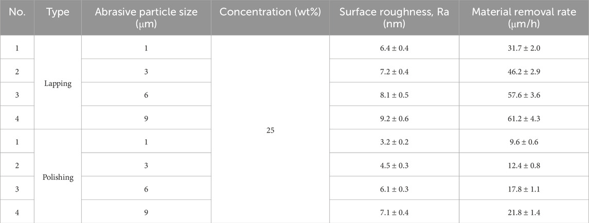
Table 4. Effect of abrasive particle size on the surface quality in the lapping and polishing stages.
Figure 9 illustrates the surface morphology of the workpiece after machining in the lapping stage with different abrasive particle sizes. As the abrasive particle size increases, the highest point on the underside of the workpiece gradually increases from 3.725 μm to 7.542 μm. Surface scratches and pits become more pronounced, indicating that the increase in abrasive particle size leads to a higher probability of surface scratches and pits, which is detrimental to subsequent polishing stages. Comparing the surfaces obtained after the lapping stage using four different diamond abrasive particle sizes, considering the occurrence of pits, scratches, and the height of micro peaks on the underside of the workpiece, 3 μm diamond abrasive particles are preferred for machining in the lapping stage.
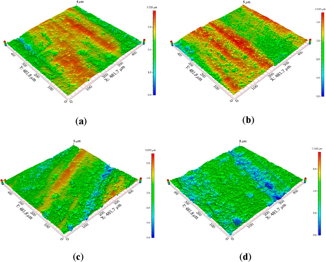
Figure 9. The surface morphology of the workpiece after 30 min of processing under different abrasive particle sizes in the lapping stage: (a) 1 μm, (b) 3 μm, (c) 6 μm, (d) 9 μm.
Figure 10 illustrates the surface morphology of the workpiece after 45 min of machining in the polishing stage with different abrasive particle sizes. As the abrasive particle size increases during the polishing stage, the number of pits on the workpiece surface gradually increases, and the highest point on the underside of the workpiece increases from 221 nm to 435 nm. Therefore, during the polishing stage, an increase in the abrasive particle size leads to a higher probability of pits generated by surface rolling on the workpiece, which is detrimental to achieving a super-smooth surface. Comparing the surfaces obtained after the polishing stage using four different diamond abrasive particle sizes and considering the occurrence of pits and scratches and the height of micro peaks on the underside of the workpiece, 3 μm diamond abrasive particles are preferred for machining in the polishing stage.
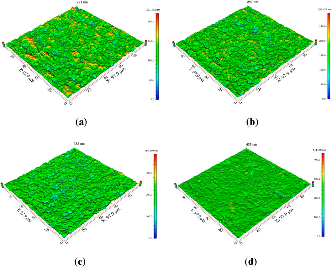
Figure 10. The surface morphology of the workpiece after 45 min of processing under different abrasive particle sizes in the polishing stage: (a) 1 μm, (b) 3 μm, (c) 6 μm, (d) 9 μm.
In summary, the optimized conditions for the integrated shear-thickening assisted abrasive lapping and polishing process are as follows: using 3 μm abrasive particle size, applying a pressure of 150 kPa, conducting the lapping stage for 30 min at a speed of 200 rpm, followed by a polishing stage for 45 min at a speed of 100 rpm. Figure 11 depicts the physical appearance and surface morphology of the workpiece after the hybrid lapping and polishing process under the optimized conditions, starting from an initial roughness of 451 nm on the SiC ceramic substrate. As a result, a smooth surface with a roughness of 9.7 nm is achieved.
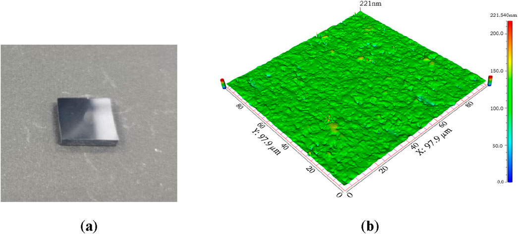
Figure 11. The (a) physical and (b) surface morphology of SiC ceramic workpiece under optimized lapping and polishing conditions.
Conclusion
This study systematically investigates the rheological behavior of shear-thickening polishing fluids with varying compositions using rheometric analysis. A clear and direct correlation is established between the rheological properties of the polishing fluid and the mass fraction of the dispersant phase, with an optimal dispersant phase mass fraction of 40 wt% identified. Subsequent experiments, conducted using a customized metallographic grinding machine, thoroughly evaluate the effects of key processing parameters. The results indicate that an optimal lapping time of 30 min and a polishing time of 45 min yield superior outcomes. Furthermore, external pressure experiments reveal that both the material removal rate and surface roughness increase with applied pressure, while reaching a plateau due to reduced fluid flow and enhanced abrasive penetration. The optimal operating pressure is determined to be 150 kPa. Additional experiments examining the influence of abrasive particle size demonstrate that both material removal rate and surface roughness increase with larger particle sizes, with 3 μm identified as the optimal size.
In conclusion, the optimized parameters for the integrated shear-thickening assisted abrasive lapping and polishing process are as follows: an abrasive particle size of 3 μm, a polishing pressure of 150 kPa, a lapping time of 30 min at 200 rpm, and a polishing time of 45 min at 100 rpm. The implementation of these parameters achieves a highly smooth surface with a surface roughness of 9.7 nm on SiC ceramic substrates, demonstrating the robust effectiveness of this advanced processing methodology.
Data availability statement
The original contributions presented in the study are included in the article/supplementary material, further inquiries can be directed to the corresponding author.
Author contributions
FP: Funding acquisition, Supervision, Writing – review and editing. HY: Writing – review and editing, Formal Analysis, Investigation. HS: Software, Data curation, Writing – original draft. ZF: Project administration, Resources, Writing – original draft. YH: Data curation, Resources, Writing – original draft. YL: Formal Analysis, Investigation, Writing – original draft. Jixuan Wu: Conceptualization, Writing – original draft, Formal Analysis, Investigation.
Funding
The author(s) declare that financial support was received for the research and/or publication of this article. This research was funded by the Open Research Fund of State Key Laboratory of Precision Manufacturing for Extreme Service Performance (Kfkt2023-16), and 2023 Major R&D Project of Lishui Economic Development Zone (2023LHT01).
Acknowledgments
The authors express their sincere gratitude to Prof. Huan Qi and his team from the Zhejiang University of Technology for their valuable assistance in conducting the experiment and analyzing the data. Additionally, special thanks are extended to Jixuan Wu, who is a student co-supervised by our team.
Conflict of interest
Author HS was employed by Zhejiang BSB Electrical Appliance Co., Ltd. Author ZF was employed by State Grid Zhejiang Lishui Power Supply Company. Author YH was employed by Zhejiang Shuolang Motor Parts Co., Ltd. Author YL was employed by Zhejiang Chuangxin Auto Air Conditioner Co., Ltd.
The remaining authors declare that the research was conducted in the absence of any commercial or financial relationships that could be construed as a potential conflict of interest.
Generative AI statement
The author(s) declare that no Generative AI was used in the creation of this manuscript.
Any alternative text (alt text) provided alongside figures in this article has been generated by Frontiers with the support of artificial intelligence and reasonable efforts have been made to ensure accuracy, including review by the authors wherever possible. If you identify any issues, please contact us.
Publisher’s note
All claims expressed in this article are solely those of the authors and do not necessarily represent those of their affiliated organizations, or those of the publisher, the editors and the reviewers. Any product that may be evaluated in this article, or claim that may be made by its manufacturer, is not guaranteed or endorsed by the publisher.
References
Chen, H., Wang, L., Peng, F., Xu, Q., Xiong, Y., Zhao, S., et al. (2023). Hydrogen retention and affecting factors in rolled tungsten: thermal desorption spectra and molecular dynamics simulations. Int. J. Hydrogen Energy 48, 30522–30531. doi:10.1016/j.ijhydene.2023.03.151
Chen, H., Wu, Z., Hong, B., Hang, W., Zhang, P., Cao, X., et al. (2024). Study on the affecting factors of material removal mechanism and damage behavior of shear rheological polishing of single crystal silicon carbide. J. Manuf. Process 112, 225–237. doi:10.1016/j.jmapro.2024.01.040
Chen, H. Y., Wang, L., Peng, F., Shen, M. M., Hang, W., Beri, T. H., et al. (2025). Efficient chemical mechanical polishing of W promoted by Fenton-like reaction between Cu2+ and H2O2. Trans. Nonferrous Metals Soc. China 35, 257–270. doi:10.1016/s1003-6326(24)66678-1
Ge, J., Lin, Y., Qi, H., Li, Y., Li, X., Li, C., et al. (2024). The impact of ultrasonic-induced jet morphology on polishing efficiency. Int. J. Mech. Sci. 284, 109764. doi:10.1016/j.ijmecsci.2024.109764
Ji, R., Shen, Q., Zhang, L., Zeng, X., and Qi, H. (2024). Novel photocatalysis-assisted mechanical polishing of laser cladding cobalt-based alloy using TiO2 nanoparticles. Powder Technol. 444, 119990. doi:10.1016/j.powtec.2024.119990
Li, M., and Xie, J. (2022). Green-chemical-jump-thickening polishing for silicon carbide. Ceram. Int. 48, 1107–1124. doi:10.1016/j.ceramint.2021.09.196
Li, H. N., Yang, Y., Zhao, Y. J., Zhang, Z., Zhu, W., Wang, W., et al. (2019). On the periodicity of fixed-abrasive planetary lapping based on a generic model. J. Manuf. Process 44, 271–287. doi:10.1016/j.jmapro.2019.05.036
Li, H. N., Zhao, Y. J., Cao, S., Chen, H., Wu, C., Qi, H., et al. (2021). Controllable generation of 3D textured abrasive tools via multiple-pass laser ablation. J. Mater Process Technol. 295, 117149. doi:10.1016/j.jmatprotec.2021.117149
Lyu, B. H., Shao, Q., Hang, W., Chen, S. H., He, Q. K., and Yuan, J. L. (2020). Shear thickening polishing of black lithium tantalite substrate. Int. J. Precis. Eng. Manuf. 21, 1663–1675. doi:10.1007/s12541-020-00362-4
Qi, H., Wen, D., Yuan, Q., Zhang, L., and Chen, Z. (2017). Numerical investigation on particle impact erosion in ultrasonic-assisted abrasive slurry jet micro-machining of glasses. Powder Technol. 314, 627–634. doi:10.1016/j.powtec.2016.08.057
Qi, H., Qin, S., Cheng, Z., Teng, Q., Hong, T., and Xie, Y. (2021a). Towards understanding performance enhancing mechanism of micro-holes on K9 glasses using ultrasonic vibration-assisted abrasive slurry jet. J. Manuf. Process 64, 585–593. doi:10.1016/j.jmapro.2021.01.048
Qi, H., Qin, S., Cheng, Z., Zou, Y., Cai, D., and Wen, D. (2021b). DEM and experimental study on the ultrasonic vibration-assisted abrasive finishing of WC-8Co cemented carbide cutting edge. Powder Technol. 378, 716–723. doi:10.1016/j.powtec.2020.10.043
Qi, H., Shi, L., Teng, Q., Hong, T., Tangwarodomnukun, V., Liu, G., et al. (2022a). Subsurface damage evaluation in the single abrasive scratching of BK7 glass by considering coupling effect of strain rate and temperature. Ceram. Int. 48, 8661–8670. doi:10.1016/j.ceramint.2021.12.077
Qi, H., Wang, Y., Qi, Z., Shi, L., Fang, Z., Zhang, L., et al. (2022b). A novel grain-based DEM model for evaluating surface integrity in scratching of RB-SiC ceramics. Materials 15, 8486. doi:10.3390/ma15238486
Shen, Q., Chen, F., Tao, Q., Ji, R., Zhang, L., Cai, D., et al. (2024). Numerical investigation of various laser-waterjet coupling methods on spot power density distribution. AIP Adv. 14, 075212. doi:10.1063/5.0217105
Tan, Y., Ni, Y., Xu, W., Xie, Y., Li, L., and Tan, D. (2023). Key technologies and development trends of the soft abrasive flow finishing method. J. Zhejiang Univ. Sci. A 24, 1043–1064. doi:10.1631/jzus.a2300038
Wang, L., Wu, M., Chen, H., Hang, W., Wang, X., Han, Y., et al. (2024). Damage evolution and plastic deformation mechanism of passivation layer during shear rheological polishing of polycrystalline tungsten. J. Mater. Res. Technol. 28, 1584–1596. doi:10.1016/j.jmrt.2023.12.122
Wu, J., Xu, P., Li, L., Li, Z., Qi, H., Wang, C., et al. (2024). Multiphase dynamic interfaces and abrasive transport dynamics for abrasive flow machining in shear thickening transition states. Powder Technol. 446, 120150. doi:10.1016/j.powtec.2024.120150
Yang, X., Song, F., Zhang, T., Yao, X., Wang, W., Zhang, Z., et al. (2024a). Surface enhancement by micro-arc oxidation induced TiO2 ceramic coating on additive manufacturing Ti-6Al-4V. Forthcoming.
Yang, X., Zhang, Z., Zhang, T., Song, F., Yao, X., Xiao, B., et al. (2024b). Multi-build orientation effects on microstructural evolution and mechanical behavior of truly as-built selective laser melting Ti6Al4V alloys. J. Mater. Res. Technol. 30, 3967–3976. doi:10.1016/j.jmrt.2024.04.031
Yuan, X., Tian, Y., Qian, C., Ahmad, S., Ma, Z., Li, L., et al. (2024). Rheology of magnetorheological shear thickening polishing fluids with micro diamond abrasive particles. J. Magn. Magn. Mater 598, 172065. doi:10.1016/j.jmmm.2024.172065
Zhang, L., Yuan, Z., Qi, Z., Cai, D., Cheng, Z., and Qi, H. (2018). CFD-Based study of the abrasive flow characteristics within constrained flow passage in polishing of complex titanium alloy surfaces. Powder Technol. 333, 209–218. doi:10.1016/j.powtec.2018.04.046
Zhang, L., Ji, R., Fu, Y., Qi, H., Kong, F., Li, H., et al. (2020). Investigation on particle motions and resultant impact erosion on quartz crystals by the micro-particle laden waterjet and airjet. Powder Technol. 360, 452–461. doi:10.1016/j.powtec.2019.10.032
Zhao, J., Jiang, E., Qi, H., Ji, S., and Chen, Z. (2020). A novel polishing method for single-crystal silicon using the cavitation rotary abrasive flow. Precis. Eng. 61, 72–81. doi:10.1016/j.precisioneng.2019.10.002
Zhou, D., Huang, X., Ming, Y., Li, X., Li, H., and Li, W. (2021). Material removal characteristics of magnetic-field enhanced shear thickening polishing technology. J. Mater. Res. Technol. 15, 2697–2710. doi:10.1016/j.jmrt.2021.09.092
Keywords: abrasive machining processes, shear-thickening fluid, abrasive lapping and polishing, SiC ceramic, surface quality
Citation: Pan F, Yuan H, Shi H, Fang Z, Huang Y, Lin Y and Wu J (2025) Study on shear-thickening-assisted abrasive lapping and polishing of SiC ceramic substrate: parameter optimization and surface quality evaluation. Front. Mater. 12:1649115. doi: 10.3389/fmats.2025.1649115
Received: 18 June 2025; Accepted: 06 August 2025;
Published: 29 August 2025.
Edited by:
Kun Li, Chongqing University, ChinaReviewed by:
Jianbo Yin, Northwestern Polytechnical University, ChinaSerhat Şap, Bingöl University, Türkiye
Jingwei Hou, The University of Queensland, Australia
Copyright © 2025 Pan, Yuan, Shi, Fang, Huang, Lin and Wu. This is an open-access article distributed under the terms of the Creative Commons Attribution License (CC BY). The use, distribution or reproduction in other forums is permitted, provided the original author(s) and the copyright owner(s) are credited and that the original publication in this journal is cited, in accordance with accepted academic practice. No use, distribution or reproduction is permitted which does not comply with these terms.
*Correspondence: Haiyang Yuan, eXVhbl9oeTE5ODBAMTI2LmNvbQ==
 Fangwei Pan1
 Haiyang Yuan