 Xiaotong Ma
 Jinyu Wang1
 Chao Bao
- 1School of Civil Engineering, North Minzu University, Yinchuan, China
- 2School of Civil Engineering and Hydraulic Engineering, Ningxia University, Yinchuan, China
The revitalization of aging urban districts can be significantly advanced through the redevelopment of existing buildings using hybrid concrete-steel structures with added stories. The connection between the newly integrated steel structure at the upper portion and the existing concrete structure at the lower portion performs a critical function in ensuring the safety and stability of hybrid concrete-steel systems. To enhance the strength and seismic resilience of the joints in these hybrid structures, this study presents a novel splice joint incorporating Engineered Cementitious Composites (ECC) concrete. A quasi-static testing method was employed to compare and analyze the failure characteristics, rotational behavior between beams and columns, hysteretic response, and skeleton curves of the proposed ECC-based splice joints and conventional concrete joints. The results reveal that the inclusion of ECC concrete significantly enhances the bonding strength at the secondary casting interface, thereby shifting the failure mode from the interface to plastic deformations at the beam ends. Furthermore, the hybrid joints demonstrated a 33% increase in the horizontal displacement threshold and an 18% improvement in load-bearing capacity, effectively limiting upper structure rotation and minimizing deformation. These findings validate the effectiveness of the proposed splice joint in enhancing the seismic behavior of hybrid concrete-steel joints. These findings highlight the enhanced seismic performance of hybrid concrete-steel structure joints and provide valuable insights for the design of lightweight steel-frame structures with added stories.
1 Introduction
The increase in renovation projects that add storeys to existing buildings is motivated by their significant economic benefits, such as high returns on investment, as well as role in improving efficiency, conserving land resources, and promoting urban revitalization (Hwang et al., 2015; Shao et al., 2021). Characterized by rapid construction timelines (Wu et al., 2014), these projects yield significant economic benefits (Lu et al., 2017; McKim et al., 2000) and exhibit a minimal environmental footprint by optimizing resource utilization and minimizing waste production (Dong et al., 2016). Furthermore, they align with green and sustainable development objectives, presenting favorable prospects for the future (Tang et al., 2014).
The lightweight steel adding-story structure is commonly employed in renovation projects. Numerous studies have examined its seismic performance. Liu et al. (2008) and Gunes et al. (2019) used numerical simulations to assess the impact of different adding-story configurations on aspects such as mass, stiffness, natural frequency, and damping ratio in lightweight steel reinforced concrete structures. These structures are characterized by a lightweight upper section and a more robust lower section, which offers flexibility in the upper part to absorb dynamic loads and provides rigidity in the lower part to maintain stability. Ma et al. (2021) evaluated the dynamic behavior of three different structural types—seismic adding-story, base-isolated, and adding-story isolated structures—under near-fault and far-field earthquake scenarios. Their findings provided critical insights into inter-story drift ratios, shear forces, and accelerations, underscoring the benefits of integrating lightweight steel into concrete adding-stories to enhance seismic resilience. Structures featuring added lightweight steel floors typically have an upper section composed of light, flexible steel and a lower section made of rigid, heavier concrete (Zhang et al., 2014; Chen et al., 2014). In the stiffness transition zones at connecting joints, it is vital to address potential weak stories—levels with significantly reduced stiffness—and whip effects that can intensify seismic impacts (Sun et al., 2015). Effective mitigation of these factors is essential for optimizing the seismic resilience of lightweight steel adding-story joints (Adhikari et al., 2019; Zhang et al., 2019; Pan et al., 2021; Ren et al., 2022). Ren et al. (2019) and Wang et al. (2022) investigated these structures' seismic resilience by applying rebar planting techniques to directly add stories to existing buildings and by reinforcing retrofit joints with carbon fiber fabric, thereby transforming joint connection forms. Furthermore, Guo et al. (2018) conducted pseudo-static tests to explore the seismic behavior of three joint types between concrete frames and lightweight steel adding-stories, with failure modes, stiffness deterioration and hysteretic behavior being examined.
Traditional rebar planting techniques offer simplicity in construction, convenience, and high economic benefits, particularly in basic reinforcement applications. Hybrid concrete-steel structures, which combine the benefits of both concrete’s compressive capacity and the tensile strength of steel structures, have been explored but lack standardized solutions for the critical juncture where these materials meet. However, they provide limited safety reserves under complex loading conditions, and the bond strength between the secondary cast concrete surfaces and existing concrete is relatively insufficient (Pan et al., 2017; Guo et al., 2013; Julio et al., 2004). As a result, the integration of Engineered Cementitious Composites (ECC) concrete with steel elements in joints remains an emerging area of research. Vavruš and Koteš. (2019) utilizing the tensile properties of fiber-reinforced concrete, employed a fiber-reinforced concrete layer to reinforce the columns of the frame structure. Yang et al. (2025a) proposed methods for calculating the restrained stress in Ultra-High Performance Concrete (UHPC) by taking into account in-situ creep measurements: collecting long-term creep data, characterizing in-situ creep during cracking, and developing a modified Double Power Law model to describe the long-term in-situ creep behavior. Xie et al. (2018) conducted experimental and analytical investigations on a highly durable composite structural system comprising polyvinyl alcohol (PVA) fiber-reinforced concrete (PVA-FRC) reinforced with glass fiber-reinforced polymer (GFRP) bars, demonstrating that PVA fiber-reinforced concrete components exhibit commendable flexural performance. ECC positively contributes to enhancing the deformation capacity and seismic performance of structures owing to its robust tensile characteristics (Zhang et al., 2023; Singh et al., 2024; Kim et al., 2024; Che et al., 2023; Qin et al., 2023).
In this study, the adding-storeys joints were strengthened based on conventional steel bar planting techniques. To further enhance the bearing capacity and seismic performance of these joints, a novel splice joint incorporating ECC concrete is proposed. It is suggested to modify the concrete material at the base of the external column and increase the contact area between the steel and concrete by using bolted connections, which may provide better load transfer and joint performance. The stress characteristics of the joints are optimized to enhance safety margins and limit overall deformation of the upper structure. This method is noted for its straightforward construction process and significant economic benefits, primarily due to reduced labor and material costs. These findings provide new design guidelines and principles for for joints in light steel adding-storey structures, contributing to safer and more efficient hybrid concrete-steel systems.
2 Research methods
To evaluate the performance of the hybrid splice joint, experimental study was performed to explore its seismic behavior through quasi-static testing.
2.1 Specimen design
The sizes of the concrete beam, concrete column, and H-shaped steel column added atop are 120 mm × 240 mm, 300 mm × 300 mm, and 120 mm × 100 mm × 10 mm × 16 mm, respectively (Specification for seismic test of, 2015). The concrete has a strength grade of C30, while the steel is grade Q235B. The hybrid joints at the base of the concrete columns are constructed using an ECC concrete mixture, consistent with the ratios specified in previous sections. This ECC mixture includes PVA fibers at a volume fraction of 1%, which enhances both tensile strength and crack resistance. The schematic diagram of the joint is depicted in Figure 1.
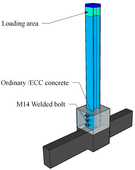
Figure 1. Schematic diagram of joint.
The longitudinal reinforcement in the concrete beams and columns consists of HRB400 grade steel bars, while the stirrups are made of HPB300 grade steel bars. The concrete cover thickness is set at 50 mm. The upper and lower structures are interconnected using four M14 chemical bolts. On both sides of the wrapped section of the H-beam column, six M14 round-head screws are affixed by welding. The specific parameters are illustrated in Figure 2.

Figure 2. Test specimen reinforcement diagram.
2.2 Specimen making and material performance
To accurately replicate the conditions of an actual construction project, the test specimen was fabricated using a two-stage concrete casting process. The procedure is as follows: First, the lower portion of the concrete beam-column joint is cast. After curing for 28 days to achieve the design strength, the locations for the bolt holes are marked and drilled. High-pressure air guns are then used to clean the holes. Subsequently, chemical adhesive tubes are inserted, and the adhesive is thoroughly mixed using mechanical tools. After the adhesive cures, bolts are installed, and the lightweight steel structure for the additional stories is assembled. For the steel column installation at the column bases, H-shaped steel columns are anchored into the concrete base, with welding points applied on both sides of each column. The surfaces are smoothed using a grinder, and quick-setting adhesive is applied for added support before welding. C50 non-shrink fine aggregate concrete is used for leveling and compaction before the installation of the additional stories. The pre-drilled holes in the upper lightweight steel structure are aligned with the anchor bolts, washers are placed underneath, and the bolts are tightened (Yang et al., 2025b; Technical specification for post, 2013). The construction steps are illustrated in Figure 3.

Figure 3. Construction steps. (a) Substructure (b) Bonded rebar (c) Install (d) Secondary casting.
Material samples are systematically collected during the concrete casting and reinforcement tying processes according to standardized procedures. Concrete cube specimens are cured under the same temperature and humidity conditions as the structural specimens. The average compressive strength of ordinary concrete is 37.5 MPa, whereas that of ECC concrete, it is 40.3 MPa, and Figure 4 illustrates the stress-strain curve of ECC. In this study, Ordinary Portland Cement (OPC) produced by Ningxia Jockey was specifically used, conforming to the P.O 42.5R grade as per Chinese standards (General Administration of Quality Supervision, 2023). The cement has a fineness of 4.4%, a consistency water consumption of 26%, with initial and final setting times of 130 min and 180 min, respectively. The cement exhibits a flexural strength of 9.0 MPa and a compressive strength of 55.6 MPa, and a specific gravity of 3.15. The high-elasticity PVA fiber used in this study has a diameter of 31 μm, and a tensile strength ranging from 1,400 to 1,600 MPa. The fiber exhibits a dry elongation at break of (17 ± 3.0)%, an elongation of 6%, and a Young’s modulus exceeding 380 GPa. These fibers are produced by Wuhan Xintu Com., China. The types of steel reinforcement and material performance indices for the components are detailed in Table 1.
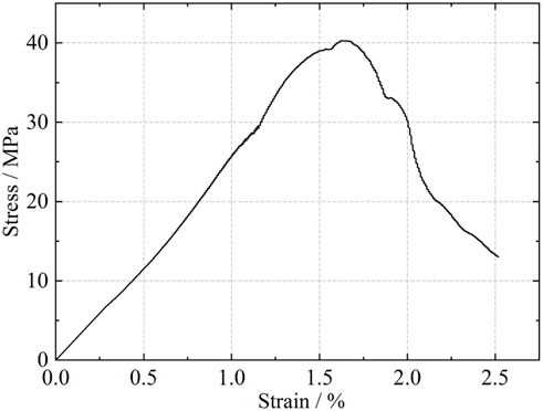
Figure 4. The stress-strain curve of ECC.

Table 1. Material performance index.
2.3 Loading mechanism
Figure 5 is the schematic diagram of the test loading apparatus. Initially, a constant axial compressive force of 0.15 axial load ratio is exerted on the top of the H-shaped column. To ensure uniform load distribution, a thick steel plate with a specified thickness of X mm is positioned at the interface between the MTS servo-hydraulic press and the H-shaped column. The MTS vertical servo-hydraulic press, equipped with horizontal rollers, accommodates horizontal movement and minimizes friction. A customized fixture connects the horizontal component of an MTS servo-hydraulic press to the reaction frame, applying a low-cycle horizontal reciprocating load of up to 100 mm at the top of the column (Specification for seismic test of, 2015). Prior to testing, the pressure transducers and hydraulic jacks underwent systematic calibration. Throughout the experimental procedure, the closed-loop feedback mechanism of the control console automatically regulated the hydraulic pressure, maintaining the vertical load constant within a tolerance margin of ±1% of the target value.
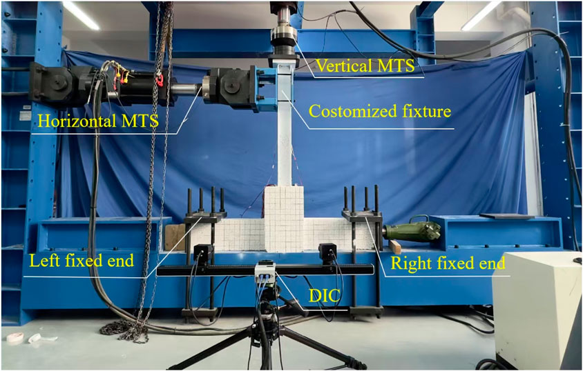
Figure 5. Loading mechanism.
2.4 Loading scheme and testing procedure
As illustrated in Figure 6, the loading scheme is implemented using a displacement-controlled approach at the end of the column. A vertical load is applied until the target design value is reached, after which the MTS vertical servo-hydraulic press dynamically maintains equilibrium by adjusting the load as necessary. After checking that all instruments are working properly, the formal loading begins. The loading speed is set to 10 mm/min to minimize any negative impacts on the specimen’s load-bearing capacity due to rapid loading (Design code for concrete structures, 2015; Wang et al., 2024; Code for seismic design of, 2016), and the incremental steps of 5 mm is utilized. Each displacement amplitude level was subjected to two complete loading-unloading cycles until the specimen fails. A specimen is considered to have failed if there is significant damage to the concrete, noticeable slippage of the steel reinforcement, or a reduction in load-bearing capacity to 85% of its initial value.
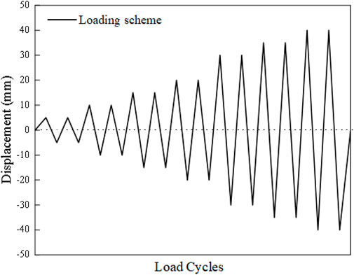
Figure 6. Loading scheme.
During the loading process, the MTS servo-hydraulic testing machine automatically records the load and corresponding displacements in both the vertical and horizontal directions. Strain gauges measure changes in the steel reinforcement and the steel column at the core region of the joint, while concrete strain is assessed using gauges placed 5 cm from the beam’s surface on both sides. Moreover, Digital Image Correlation (DIC) optical measurement technology is employed for comprehensive monitoring of the core region of the joints (Ribeiro et al., 2022; Khalilzadehtabrizi et al., 2021; Zhou et al., 2021; Sun et al., 2023; Liu et al., 2025; Li et al., 2023). Prior to loading, an irregular black-and-white speckle pattern is manually applied to the surface of the component. The camera then captures initial images of the nodes in the unloaded state, as well as the deformation images at each loading stage. Through post-processing using displacement field analysis algorithms, full-field displacement contours and quantitative strain distribution data are derived for each nodal specimen. The DIC methodology enables precise visualization of structural behavior under applied loads, which is critical for evaluating material performance and validating finite element models in civil engineering applications. The experimental procedure mainly includes the following steps: first, spray a layer of white matte paint on the node area of the specimen; then randomly and irregularly apply black speckle patterns to the surface; use an adjustable stereoscopic camera system to capture images and collect data, and then process the collected data using the software accompanying the DIC equipment to obtain related results, such as displacement contour maps, damage contour maps, and strain contour maps of the specimen.
3 Test results and analysis
3.1 Test phenomenon
This study mainly focuses on the phenomenon of forward loading tests, where the observations for both forward and reverse loading tests are identical. Initially, applying an axial force and introducing a horizontal displacement of 5 mm does not yield significant changes in the ordinary concrete joint. At a displacement of 10 mm, fine cracks begin to emerge in the secondary pouring section under tensile stress, as illustrated in Figure 7a. When the displacement is increased to 15 mm, the existing cracks widen, and new oblique cracks form at the end of the beam, as depicted in Figure 7b. Figure 7c indicates that at 20 mm displacement, the structure endures a bending moment, resulting in outward-extending cracks at the top of the column. At 25 mm, as shown in Figure 7d, a primary crack develops at a 45-degree angle at the column end, forming an X-shaped pattern, while the cracks in the secondary pouring section continue to expand. Finally, Figure 7e reveals that at 30 mm displacement, the X-shaped diagonal crack at the column’s end progresses, and the secondary pouring section exhibits significant warping, with the maximum crack width exceeding 5.0 mm.
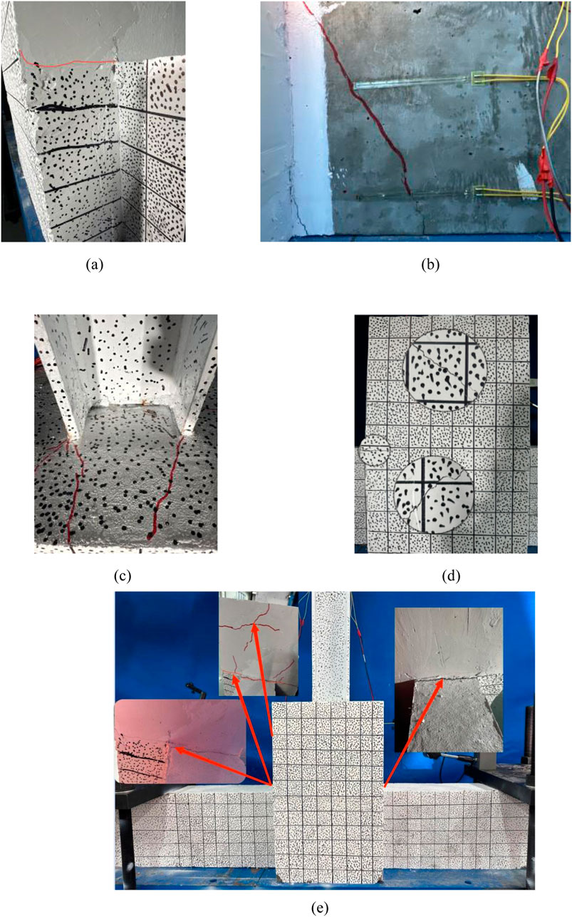
Figure 7. The phenomenon of ordinary joints experimentation. (a) Pouring surface crack (b) Diagonal cracking (c) Column top crack (d) Column diagonal crack (e) Whole schematic.
Figure 8 depicts the schematic diagram of crack formation in the new hybrid joint. At a horizontal displacement of 5 mm, the joint shows no cracking. As shown in Figure 8a, when the displacement increases to 10 mm, three small cracks emerge at the beam’s top. At 15 mm, diagonal cracks oriented at a 45-degree angle appear at the beam end, where the crack width reaches the fracture threshold, as recorded by the concrete strain gauge, illustrated in Figure 8b. As the displacement extends, the cracks continue to widen. At 30 mm, tensile cracks develop at the beam end, as shown in Figure 8c, and at 40 mm, the concrete at the beam end crushes, as seen in Figure 8D. Consequently, the joint’s lateral bearing capacity diminishes, leading to the termination of the test. Unlike ordinary concrete joints, this hybrid design substantially mitigates crack formation in the secondary pouring section. It efficiently redistributes internal forces and, with the help of horizontal anchor bolts, promotes a more uniform stress distribution within the concrete. This arrangement not only slows the crack propagation but also reduces their width, thereby enhancing the structural integrity and minimizing the damage at the outer column base.
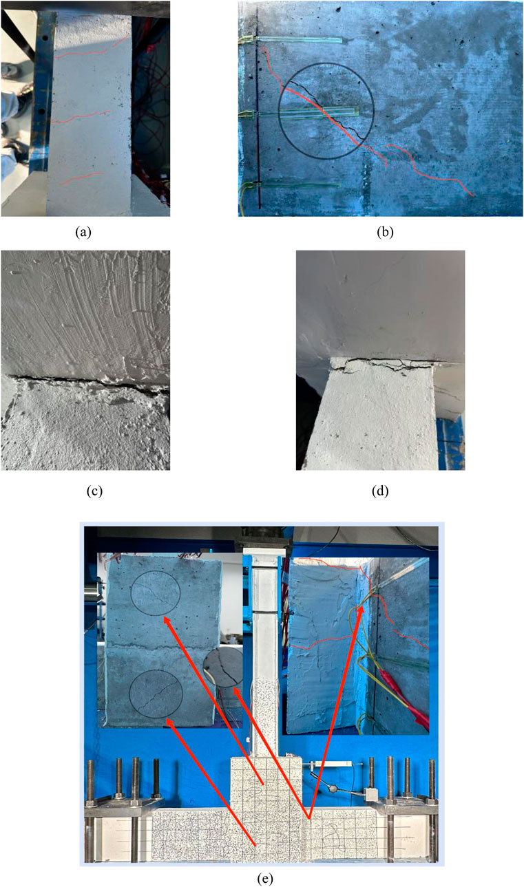
Figure 8. The phenomenon of hybrid connection joints experimentation. (a) Beam top crack (b) Diagonal crack (c) Tensile crack (d) Compression crack (e) Whole schematic.
The analysis of the failure processes in ordinary and hybrid joints reveals that hybrid joints enhance the overall integrity of the connection and modify the failure mode. These joints strengthen the connection to H-section steel columns and exhibit superior lateral resistance. Furthermore, hybrid joints not only extend the horizontal displacement limit of the structure but also enhance its seismic resistance.
3.2 Hysteresis curve
Figure 9 displays the load-displacement curves for two types of joints. Initially, the hysteresis loops of both joints show linear behavior with minimal residual deformation. As the horizontal displacement increases, the hysteresis loop of the ordinary joint begins to show pinching behavior, reflecting a decrease in the curve’s slope and reduced stiffness. In contrast, the hybrid joint maintains higher ultimate horizontal load capacity and stronger lateral resistance at comparable displacement levels. Moreover, it exhibits a larger hysteresis loop envelope, indicative of enhanced energy dissipation capabilities. The horizontal resistance of both joints is greater during forward loading than reverse loading, largely due to the partial expulsion of concrete during forward movement. At a horizontal displacement of 30 mm, significant cracking at the second casting interface of the ordinary joint causes loading to halt. At 40 mm of displacement, the hybrid joint’s horizontal bearing capacity falls below 85% of the peak load, signaling the failure criterion.
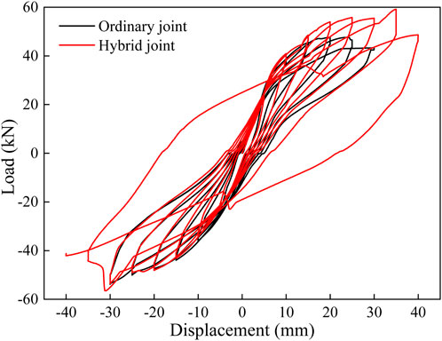
Figure 9. Hysteresis curve of loading point.
The energy absorption and dissipation of the structure subjected to cyclic loading can be determined from the hysteresis curve, as shown in Figure 10. The energy dissipation capacity of a component is quantified by the area within the hysteresis loop, representing the work done by the component during each cycle. This area is typically calculated as the product of load magnitude and displacement; hence, a larger area suggests increased energy dissipation. The energy dissipation ability of the hybrid joint is comparable to or slightly exceeding that of the ordinary joint, indicating its higher potential to withstand significant seismic events and large displacements.

Figure 10. Energy dissipation of loading point.
From the perspective of hysteresis curve and energy analysis, the hybrid joint alters the force characteristics of the joints, enhancing energy dissipation capacity and lateral resistance. This joint more effectively restricts the deformation of the upper structure during seismic activity, ensuring the reliability of the core area of the joint and achieving the intended effect.
3.3 Skeleton curve
Skeletal curves were obtained by connecting the peak points of the maximum horizontal displacement in each loading cycle, as illustrated in Figure 11. These curves offer a simplified view of load-displacement behavior, facilitating comparative analysis. The skeletal curves for both joints show consistent and symmetrical development under cyclic loading. During forward loading phases, both curves exhibit distinct inflection points. The ordinary joint exhibits a minor and statistically insignificant increase in ultimate load capacity, while the hybrid joint displays a substantial increase. Moreover, the hybrid joint experiences more pronounced degradation of skeletal stiffness, with a 33.33% greater horizontal load reduction displacement than the ordinary joint. This joint also shows an 18% enhancement in ultimate horizontal load capacity over the ordinary joint, indicating a significant improvement in its load-bearing capacity. Such enhancements suggest that the hybrid joint can withstand larger forces at the same deformation and undergo smaller deformations for equivalent forces.
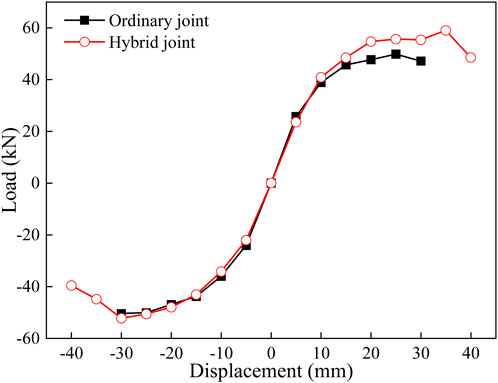
Figure 11. Skeleton curve of loading point.
3.4 Stiffness degradation curve
Structural stiffness declines with increasing cycles of low-cycle reciprocating loads. Stiffness degradation within the core region of the joint is evaluated using secant stiffness, defined as the ratio of change in load to change in displacement at a specific point. During loading, horizontal displacement and secant stiffness are plotted on the x and y-axis, respectively. According to reference (Ren et al., 2022), this coefficient is derived using Formula 1:
In this context, +Fi and -Fi denote the maximum positive and negative loads, respectively, during the ith cycle, while + Xi and -Xi indicate the peak displacements. The symbol ± indicates the direction of the load. Figure 12 displays the stiffness degradation curves for both joints. Throughout the loading process, the skeletal curves of both the ordinary and hybrid joints remain aligned. As load displacement escalates, the rate of stiffness degradation for both joints diminishes. Although the hybrid joint initially exhibits higher stiffness than the ordinary joint, this is attributed to the superior mobility and densification of external column plinths, which are cast with ordinary concrete. In contrast, ECC concrete with PVA fibers may restrict concrete mobility and contain small voids. Nevertheless, the hybrid joint demonstrates superior stiffness performance overall, significantly enhancing the integrity of the entire structure.
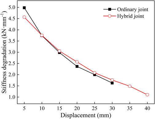
Figure 12. Stiffness degradation curve of loading point.
4 Detection and analysis based on DIC
4.1 Shear deformation
The shear angle is a critical parameter for analyzing shear deformation in structures and understanding their deformation behaviors and mechanical properties. To investigate the shear deformation behavior of specimens under forward loading with low-frequency cyclic loading, the post-processing function of DIC was used (Zhou et al., 2021). Different color shades visualized the shear angle magnitude, clearly highlighting the deformation characteristics across structures with various column base materials, as illustrated in Figures 13, 14.
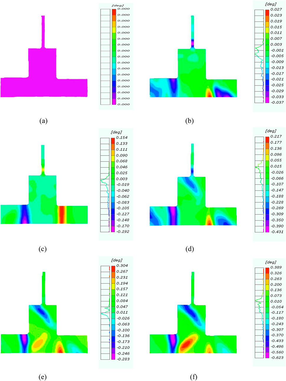
Figure 13. Shear angle of ordinary joint. (a) Initial state. (b) Displacement of 5 mm. (c) Displacement of 10 mm. (d) Displacement of 15 mm. (e) Displacement of 20 mm. (f) Displacement of 30 mm.

Figure 14. Shear angle of hybrid connection joint. (a) Displacement of 5 mm. (b) Displacement of 10 mm. (c) Displacement of 15 mm. (d) Displacement of 25 mm. (e) Displacement of 30 mm. (f) Displacement of 40 mm.
For ordinary joints, shear deformation primarily occurs at the bottom of the beam in the loading direction and at the top in the opposite direction for horizontal displacements within 10 mm. As displacement increases to 15 mm, shear deformation manifests at a 45° angle in the opposite direction at the external column base. At 20 mm, the concrete column exhibits symmetric shear deformation around the axis of the top beam. At 25 mm, the shear deformation progressively extends beyond the observations at 20 mm. In the upper H-section steel, significant shear deformation is evident at the junction with the external column base for displacements up to 15 mm. As shear deformation in the external column base concrete intensifies, that in the H-section steel begins to diminish, resulting in deformation propagation from the structure’s weaker components.
The shear deformation pattern in the hybrid joint at the base of the concrete column mirrors that of the ordinary joint, though the hybrid joint exhibits enhanced tensile behavior and anchorage. Enhanced tensile behavior and improved anchorage, attributed to H-section steel welded bolts, resulting from reduced shear deformation at the external column base. Consequently, the upper H-section steel and the external column base integrate into a nearly singular entity, broadening the range of the shear angle. In the hybrid joint, the tensile properties of ECC concrete are fully utilized, augmenting the bond between the secondary cast surface and the H-section steel welded bolts, thereby reinforcing the structural integrity of the core region.
4.2 Damage analysis
Analyzing numerical values provides an intuitive insight into deformation behaviors and failure mechanisms, such as the location and development of concrete cracks. This method is effective in studying the overall structural response to changes in loading conditions.
Figures 15, 16 illustrate the differences in concrete damage distribution between ordinary and hybrid joints during the loading process. In the situation of ordinary joints, initial cracks form at the intersection of the beams and columns, and as horizontal displacement increases, these cracks propagate, eventually leading to 45° diagonal cracking in the concrete columns, ultimately resulting in failure. For the new hybrid joint configuration, initial cracks appear at both ends of the beam and progressively expand with increasing horizontal displacement. The hybrid joint design effectively minimizes damage to the secondary pouring concrete, enabling the upper H-shaped steel and concrete columns to function as a unified structural element. The deformation in the core region of the hybrid joint is better coordinated, while the deformation induced by the added layer is constrained, thereby demonstrating the structural integrity of the hybrid joint. Additionally, the strain in the upper H-shaped steel column exceeds that in the core area of the joint, resulting in noticeable displacement. This observation indicates that hybrid joints, which incorporate externally wrapped ECC concrete at the column base, demonstrate improved structural integrity.
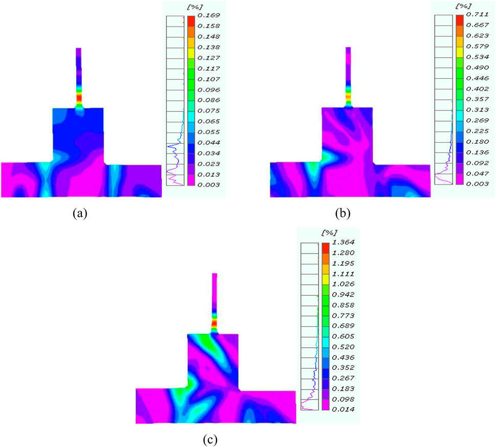
Figure 15. Ordinary connection joint damage process. (a) Initial crack (b) Development stage (c) Destruction stage.
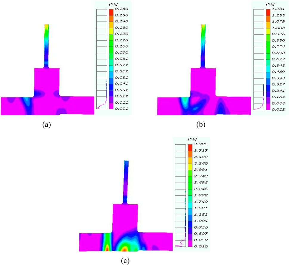
Figure 16. Hybrid connection joint damage process. (a) Initial crack (b) Development stage (c) Destruction stage.
4.3 Angle between beam and column
In assessing seismic behavior, the rotational displacement at the joints between upper and lower structures is a critical metric for evaluating structural deformation. The lightweight steel frame structure, augmented with additional stories, has the characteristic of having lighter upper stories than the lower ones. Using the DIC technique, the angular displacement between the beam and column in two specimens under low-cycle reciprocating loads were analyzed, as shown in Figure 17.

Figure 17. Angle variation diagram.
The angle between the beam and the column at the connection joint reveals that the two curves diverge once the horizontal displacement reaches 10 mm. This angular difference is more pronounced during forward loading, whereas the rotational displacement increases during reverse loading. The ECC concrete column base effectively restricts relative rotation and structural deformation between the upper and lower parts of structures, thereby enhancing the overall stiffness of the joint core area.
5 Conclusion
In this study, the performance characteristics of hybrid and ordinary joints under low-cycle reciprocating loads was conducted.
1. In ordinary joints, the base of the column displayed intersecting cracks due to fractures on the secondary pouring surface, which compromised the structural integrity. However, in the hybrid joints incorporating ECC, failure occurred at the beam hinge rather than at the column base. This design significantly increased the joint stiffness, which not only enhanced the overall stability but also effectively limited damage.
2. The application of ECC concrete enhanced the stress performance of joints due to its high tensile strength and strain-hardening behavior, which improve crack resistance and overall stress distribution. Additionally, the hysteresis curve of hybrid joints exhibits a robust shape, indicative of enhanced energy dissipation and absorption capacities, further contributing to the improved performance of the joints.
3. Hybrid joints showed greater horizontal displacement and bearing capacity compared to ordinary joints due to their enhanced energy dissipation and load distribution capabilities. Their stiffness degradation curves were smoother, delaying bearing capacity reduction and highlighting this advantage. By restricting the angle between beams and columns, hybrid joints effectively minimized deformation in the upper structure, further contributing to their increased horizontal displacement and bearing capacity.
4. The present study is mainly centered on the experimental investigation of the hysteretic behavior of ECC-based splice joints and conventional concrete joints. In future research, finite element parameter analysis will be carried out to further delve into the engineering application of the innovative ECC-based splice joints (Miceli et al., 2025).
The utilisation of ECC concrete in hybrid concrete-steel structures with additional stories presents a range of prospective benefits with regard to structural performance and long-term durability. Nevertheless, the higher initial costs of ECC and the specialised handling requirements could pose challenges. From a cost-benefit perspective, while the initial material expenses for ECC are higher compared to conventional concrete, the long-term benefits, including reduced maintenance costs and extended service life, may offset these initial costs. The combination of ECC and steel in hybrid designs can optimize both cost and performance, especially in structures that require additional stories. Constructability is also an important consideration, as ECC may require more specialized handling during construction, which could impact labor and equipment costs. Overall, the long-term benefits, including lower maintenance and reduced life-cycle costs, make ECC a potentially cost-effective choice for such applications.
Data availability statement
The raw data supporting the conclusions of this article will be made available by the authors, without undue reservation.
Author contributions
XM: Funding acquisition, Supervision, Writing – original draft. JW: Formal Analysis, Writing – review and editing. TG: Writing – review and editing, Software. CB: Formal Analysis, Funding acquisition, Writing – review and editing. FC: Writing – review and editing, Data curation.
Funding
The author(s) declare that financial support was received for the research and/or publication of this article. Financial support from Special fund for Basic Scientific Research Business Expenses of Central Universities of North Minzu University (Grant No. 2023ZRLG14), Ningxia Key Research and Development Program (Grant No. 2021BEG03022), National Natural Science Foundation of China (Grant No. 52368011), West Light Foundation of Chinese Academy of Sciences (Grant No. XAB2021YW14), Outstanding Youth Program of Ningxia Natural Science Foundation (Grant No. 2023AAC05015).
Conflict of interest
The authors declare that the research was conducted in the absence of any commercial or financial relationships that could be construed as a potential conflict of interest.
Generative AI statement
The author(s) declare that no Generative AI was used in the creation of this manuscript.
Any alternative text (alt text) provided alongside figures in this article has been generated by Frontiers with the support of artificial intelligence and reasonable efforts have been made to ensure accuracy, including review by the authors wherever possible. If you identify any issues, please contact us.
Publisher’s note
All claims expressed in this article are solely those of the authors and do not necessarily represent those of their affiliated organizations, or those of the publisher, the editors and the reviewers. Any product that may be evaluated in this article, or claim that may be made by its manufacturer, is not guaranteed or endorsed by the publisher.
References
Adhikari, A., Rao, K. R. M., Gautam, D., and Chaulagain, H. (2019). Seismic vulnerability and retrofitting scheme for low-to-medium rise reinforced concrete buildings in Nepal. J. Build. Eng. 21, 186–199. doi:10.1016/j.jobe.2018.10.015
Che, J. L., Guo, Z. W., Yang, P., and Liu, H. (2023). Experimental investigation on seismic behavior of brick masonry wall strengthened with ECC splint. Constr. Build. Mater. 391, 131627. doi:10.1016/j.conbuildmat.2023.131627
Chen, H., Wei, J. P., and Wang, T. (2014). The seismic performance analysis of light steel story-adding on steel frame. Appl. Mech. Mater. 501, 1573–1579. doi:10.4028/www.scientific.net/AMM.501-504.1573
Code for seismic design of buildings: gb50011-2010 (2016). Beijing: China Architecture & Building Press.
Design code for concrete structures: gb50010-2010 (2010). Beijing: China Architecture & Building Press.
Dong, H. Y., Guo, Y. H., and Du, C. (2016). Test research on seismic performance of story-adding frame structure. Teh. Vjesn./Tech. Gaz. 23 (3), 675–684. doi:10.17559/TV-20150314121011
General Administration of Quality Supervision (2023). Inspection and quarantine of the people's Republic of China and the standardization administration of China. GB 175 -2023: common Portland cement. Beijing, China: Standards Press of China.
Gunes, B., Cosgun, T., Sayin, B., and Mangir, A. (2019). Seismic performance of an existing low-rise RC building considering the addition of a new storey. Archit. Mag. 18 (3), 459–475. doi:10.7764/rdlc.18.3.459
Guo, R., Zhao, S. W., and Liu, K. (2013). Experimental study on seismic behavior of strengthening joints in light steel adding storey. Adv. Mater. Res. 671, 1480–1483. doi:10.4028/www.scientific.net/AMR.671-674.1480
Guo, H. C., Xiao, F., Liu, Y. H., and Liang, G. (2018). Experimental and numerical study on the mechanical behavior of Q460D high-strength steel bolted connections. J. Constr. Steel Res. 151, 108–121. doi:10.1016/j.jcsr.2018.09.012
Hwang, H. J., Eom, T. S., Park, H. G., Lee, S. H., and Kim, H. S. (2015). Cyclic loading test for beam-column connections of concrete-filled U-shaped steel beams and concrete-encased steel angle columns. J. Struct. Eng. 141 (11), 04015020. doi:10.1061/(ASCE)ST.1943-541X.0001242
Julio, E. N. B. S., Branco, F. A. B., and Silva, V. D. (2004). Concrete-to-concrete bond strength. Influence of the roughness of the substrate surface. Constr. Build. Mater. 18 (9), 675–681. doi:10.1016/j.conbuildmat.2004.04.023
Khalilzadehtabrizi, S., Seifiasl, A., and Asl, M. H. (2021). Measurement of deformation patterns in steel plate shear walls subjected to cyclic loading based on multi-target digital image correlation (MT-DIC). Structures 33, 2611–2627. doi:10.1016/j.istruc.2021.06.007
Kim, S., Shin, J., and Kim, W. (2024). Assessing the seismic performance of exterior precast concrete joints with ultra-high-performance fiber-reinforced concrete. Int. J. Concr. Struct. Mater. 18 (1), 10. doi:10.1186/s40069-023-00646-9
Li, W. B., Huang, Y., Liu, Z. H., and Liu, L. (2023). Study on influencing factors of synergistic deformation between built-in strain sensor and asphalt mixture. Case Stud. Constr. Mater. 18, e01993. doi:10.1016/j.cscm.2023.e01993
Liu, Y., Gao, X. W., and Zhang, T. (2008). Analysis of seismic performance of the story-adding structures of light-weight steel based on SAP2000. Earthq. Resist. Eng. Retrofit. 30 (6), 100–104. doi:10.16226/j.issn.1002-8412.2008.06.009
Liu, H., Zhang, B., Yan, L. W., Meng, X., Zhou, J., Cui, J., et al. (2025). Rebar characterization using dual-polarization GPR. NDT E Int. 154, 103391. doi:10.1016/j.ndteint.2025.103391
Lu, Z., He, X. D., and Zhou, Y. (2017). Studies on damping behavior of vertically mixed structures with upper steel and lower concrete substructures. Struct. Des. Tall Special Build. 26 (17), e1392. doi:10.1002/tal.1392
Ma, X. T., Bao, C., Doh, S. I., Lu, H., Zhang, L., Ma, Z., et al. (2021). Dynamic response analysis of story-adding structure with isolation technique subjected to near-fault pulse-like ground motions. Phys. Chem. Earth 121, 102957. doi:10.1016/j.pce.2020.102957
McKim, R., Hegazy, T., and Attalla, M. (2000). Project performance control in reconstruction projects. J. Constr. Eng. Manag. 126 (2), 137–141. doi:10.1061/(ASCE)0733-9364(2000)126:2(137)
Miceli, E., Gino, D., and Pl, C. (2025). Reliability assessment of robustness for reinforced concrete moment resisting frames. Dev. Built Environ. 21, 100639. doi:10.1016/j.dibe.2025.100639
Pan, Z. H., Si, Q., Zhou, Z. B., Zhang, Y., Zhu, Y., and Chen, X. (2017). Experimental and numerical investigations of seismic performance of hybrid joints with bolted connections. J. Constr. Steel Res. 138, 867–876. doi:10.1016/j.jcsr.2017.09.001
Pan, X. Z., Qiao, S. F., Li, H., Gao, H., Ma, H., and Yao, L. (2021). Seismic behaviour of a new type of external hoop assembled joint for RC Frame-added layer hybrid structure. Structures 32, 170–193. doi:10.1016/j.istruc.2021.03.016
Qin, F. J., Wei, X. Y., Lu, Y. F., Zhang, Z., Di, J., and Yin, Z. (2023). Flexural behaviour of high strength engineered cementitious composites (ECC)-reinforced concrete composite beams. Case Stud. Constr. Mater. 18, e02002. doi:10.1016/j.cscm.2023.e02002
Ren, X., Gong, S., and Lu, Y. (2019). Performance evaluation of seismic strengthened irregular RC–steel hybrid frames. J. Perform. Constr. Facil. 33 (1), 04018093. doi:10.1061/(ASCE)CF.1943-5509.0001242
Ren, L. X., Wei, Z. F., Liang, N. H., Liu, X., and Deng, Z. (2022). Mechanical behavior of multi-scale fiber-reinforced concrete for secondary tunnel lining: field test and numerical simulation. Case Stud. Constr. Mater. 17, e01669. doi:10.1016/j.cscm.2022.e01669
Ribeiro, B., Asaue, H., Hattori, A., Shiotani, T., Kobayashi, T., Sato, J., et al. (2022). Load carrying behavior of concrete reinforced with bundled BFRP bars by using DIC. Case Stud. Constr. Mater. 17, e01538. doi:10.1016/j.cscm.2022.e01538
Shao, Z. H., Xu, X. S., and Wang, N. (2021). Seismic performance analysis of new frame columns in a story-adding frame structure. Earth Environ. Sci. 783 (1), 012040. doi:10.1088/1755-1315/783/1/012040
Singh, M., Saini, B., and Chalak, H. D. (2024). Efficacy of hybrid fibre reinforced ECC in RC exterior beam-column connections. Iran. J. Sci. Technol. Trans. Civ. Eng. 48, 2111–2126. doi:10.1007/s40996-024-01455-0
Specification for seismic test of buildings: jgj/T 101-2015. (2015). Beijing: China Architecture & Building Press.
Sun, X. H., Xie, L. P., and Ji, F. (2015). Dynamic analysis of concrete frame structure with story-adding steel structure at the top. Appl. Mech. Mater. 744, 65–70. doi:10.4028/www.scientific.net/AMM.744-746.65
Sun, Z. Y., Zheng, Y., Sun, Y. L., Shao, X., and Wu, G. (2023). Deformation ability of precast concrete columns reinforced with steel-FRP composite bars (SFCBs) based on the DIC method. J. Build. Eng. 68, 106083. doi:10.1016/j.jobe.2023.106083
Tang, X. Q., Wu, P. C., and Ma, S. C. (2014).The seismic response study of light steel story adding structure considering the effects of damping. Adv. Mater. Res. 1030: 948–951. doi:10.4028/www.scientific.net/AMR.1030-1032.948
Technical specification for post-installed fastenings in concrete structures: JGJ 145-2013 S. (2013). Beijing: China Architecture & Building Press.
Vavruš, M., and Koteš, P. (2019). Numerical comparison of concrete columns strengthened with layer of fiber concrete and reinforced concrete. Transp. Res. Proced. 40, 920–926. doi:10.1016/j.trpro.2019.07.129
Wang, J., Li, H. F., Wu, S. Z., Liang, E., and Wang, Z. (2022). Numerical simulation and field test of the interaction between existing station and enclosure in open excavation and adding stories construction. Appl. Sci. 12 (19), 9563. doi:10.3390/app12199563
Wang, K. Y., Cao, J., Ye, J. H., Qiu, Z., and Wang, X. (2024). Discrete element analysis of geosynthetic-reinforced pile-supported embankments. Constr. Build. Mater. 449, 138448. doi:10.1016/j.conbuildmat.2024.138448
Wu, P. C., Tang, X. Q., and Ma, S. C. (2014). Research of application status and existing problems for light steel structure with added-storey. Adv. Mater. Res. 1030, 999–1002. doi:10.4028/www.scientific.net/AMR.1030-1032.999
Xie, T. Y., Mohamed Ali, M. S., Visintin, P., Oehlers, D. J., and Sheikh, A. H. (2018). Partial interaction model of flexural behavior of PVA fiber–reinforced concrete beams with GFRP bars. J. Compos. Constr. 22 (5), 04018043. doi:10.1061/(ASCE)CC.1943-5614.0000878
Yang, G., Zhao, H. T., Hu, Z. L., Zhang, W., Xiang, Y., Jin, M., et al. (2025a). Prediction of restrained stress for UHPC: considering relationship between long-term and in-situ creep. Constr. Build. Mater. 484, 141722. doi:10.1016/j.conbuildmat.2025.141722
Yang, Q. S., Li, H. H., Zhang, L. L., Guo, K., and Li, K. (2025b). Nonlinear flutter in a wind-excited double-deck truss girder bridge: experimental investigation and modeling approach. Nonlinear Dyn. 113, 6427–6445. doi:10.1007/s11071-024-10496-z
Zhang, T., Zuo, Y. Z., Teng, H. W., and Liu, H. (2014). Study on Rayleigh damping in dynamic analysis for story-adding RC structure of light-weight steel. Appl. Mech. Mater. 482, 123–128. doi:10.4028/www.scientific.net/AMM.482.123
Zhang, H., Wu, K., Cao, P. Z., Xu, C., and Ren, L. (2019). Failure modes and damage processes of vulnerable stories in SRC-RC hybrid frames. J. Perform. Constr. Facil. 33 (5), 04019057. doi:10.1061/(ASCE)CF.1943-5509.0001323
Zhang, Z. Y., Ji, Y. C., and Ji, W. H. (2023). Durability performance investigation for engineering fiber cementitious composites (ECC): review. Polymers 15 (4), 931. doi:10.3390/polym15040931
Keywords: hybrid structure, ECC, experimental study, hysteretic behavior, seismic performance, failure characteristics
Citation: Ma X, Wang J, Guo T, Bao C and Cao F (2025) Experimental study on seismic performance of a novel splice joint in hybrid concrete-steel structures. Front. Mater. 12:1657980. doi: 10.3389/fmats.2025.1657980
Received: 02 July 2025; Accepted: 22 August 2025;
Published: 03 September 2025.
Edited by:
Muhammad Usman Hanif, University of Southern Denmark, DenmarkReviewed by:
Paolo Castaldo, Polytechnic University of Turin, ItalyAmir Ali Shahmansouri, Washington State University, United States
Copyright © 2025 Ma, Wang, Guo, Bao and Cao. This is an open-access article distributed under the terms of the Creative Commons Attribution License (CC BY). The use, distribution or reproduction in other forums is permitted, provided the original author(s) and the copyright owner(s) are credited and that the original publication in this journal is cited, in accordance with accepted academic practice. No use, distribution or reproduction is permitted which does not comply with these terms.
*Correspondence: Xiaotong Ma, MjAxNTAzOUBueHUuZWR1LmNu